2015 MITSUBISHI OUTLANDER III change
[x] Cancel search: changePage 190 of 446
Lane Departure Warning System (LDW) (if so equipped)
Features and controls 5-113
5
N00581100023
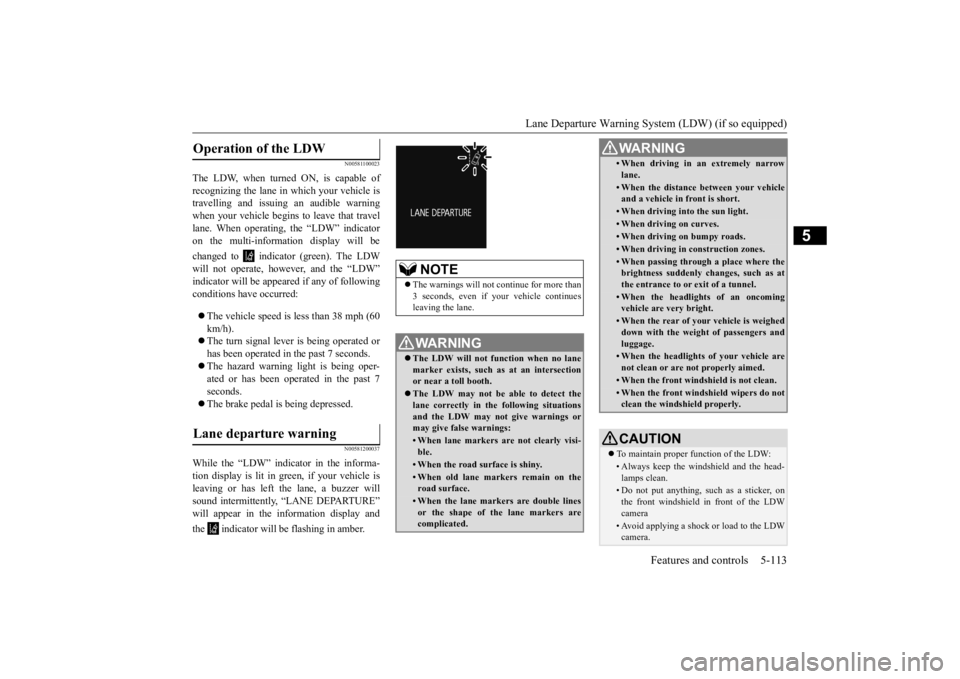
The LDW, when turned ON, is capable of recognizing the lane in which your vehicle is travelling and issuing an audible warningwhen your vehicle begins to leave that travel lane. When operating,
the “LDW” indicator
on the multi-information display will be changed to indicator (green). The LDW will not operate, however, and the “LDW” indicator will be appeared if any of following conditions have occurred: The vehicle speed is less than 38 mph (60 km/h). The turn signal lever is being operated or has been operated in the past 7 seconds. The hazard warning light is being oper- ated or has been operated in the past 7 seconds. The brake pedal is being depressed.
N00581200037
While the “LDW” indicator in the informa- tion display is lit in gr
een, if your vehicle is
leaving or has left the lane, a buzzer will sound intermittently, “LANE DEPARTURE” will appear in the information display and the indicator will be flashing in amber.Operation of the LDW
Lane departure warning
NOTE
The warnings will not
continue for more than
3 seconds, even if your vehicle continues leaving the lane.WA R N I N G The LDW will not function when no lane marker exists, such as at an intersection or near a toll booth. The LDW may not be able to detect the lane correctly in th
e following situations
and the LDW may not
give warnings or
may give false warnings:• When lane markers are not clearly visi-ble.• When the road surface is shiny.• When old lane markers remain on the road surface.• When the lane markers are double linesor the shape of the lane markers are complicated.
• When driving in an extremely narrowlane.• When the distance
between your vehicle
and a vehicle in
front is short.
• When driving into the sun light.• When driving on curves.• When driving on bumpy roads.• When driving in construction zones.• When passing through a place where the brightness suddenly changes, such as at the entrance to or exit of a tunnel.• When the headlights of an oncomingvehicle are very bright. • When the rear of your vehicle is weigheddown with the weight of passengers and luggage.• When the headlights
of your vehicle are
not clean or are not properly aimed.• When the front windshield is not clean.• When the front windshield wipers do not clean the windshield properly.CAUTION To maintain proper function of the LDW:• Always keep the windshield and the head- lamps clean.• Do not put anything, such as a sticker, onthe front windshield in front of the LDWcamera • Avoid applying a shock or load to the LDWcamera. WA R N I N G
BK0211800US.book 113 ページ 2014年3月12日 水曜日 午後2時42分
Page 195 of 446
Rear-view camera (if so equipped) 5-118 Features and controls
5
A window tint that affects the radio wave signals is installed.
N00532900081
If new wheels with new tire inflation pressure sensors are installed, their ID codes must be programmed into the tire pressure monitoringsystem. Have tire and wheel replacement per- formed by an authorized Mitsubishi Motors dealer to avoid the ri
sk of damaging the tire
inflation pressure sensors. If the wheel replacement is not done by an authorized Mitsubishi Motors dealer
, it is not covered by
your warranty.
N00533001233
Your tire pressure monitoring system oper-ates on a radio frequency subject to Federal Communications Comm
ission (FCC) Rules
(For vehicles sold in U.S.A.) and IndustryCanada Rules (For vehicles sold in Canada). This device complies with part 15 of FCC Rules and Industry Ca
nada licence-exempt
RSS standard(s). Operation is subject to the following two con- ditions. This device may not
cause harmful inter-
ference. This device must ac
cept any interference
received, including interference that maycause undesired operation.
N00546201196
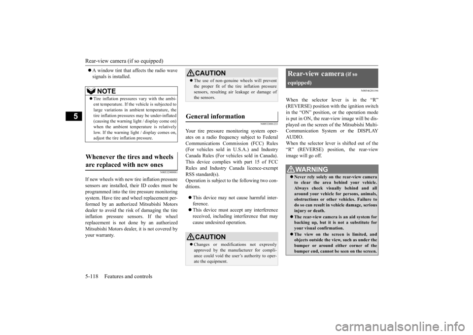
When the selector lever is in the “R”(REVERSE) position with the ignition switchin the “ON” position,
or the operation mode
is put in ON, the rear-view image will be dis- played on the screen of the Mitsubishi Multi-Communication System or the DISPLAY AUDIO. When the selector lever is shifted out of the “R” (REVERSE) position, the rear-view image will go off.
NOTE
Tire inflation pressures vary with the ambi- ent temperature. If the
vehicle is subjected to
large variations in am
bient temperature, the
tire inflation pressures may be under-inflated(causing the warning li
ght / display come on)
when the ambient temperature is relatively low. If the warning light / display comes on,adjust the tire inflation pressure.
Whenever the tires and wheels are replaced with new ones
CAUTION The use of non-genuine wheels will prevent the proper fit of the tire inflation pressuresensors, resulting air
leakage or damage of
the sensors.
General information
CAUTION Changes or modifica
tions not expressly
approved by the manufacturer for compli-ance could void the user’s authority to oper- ate the equipment.
Rear-view camera
(if so
equipped)
WA R N I N G Never rely solely on the rear-view camera to clear the area behind your vehicle. Always check visua
lly behind and all
around your vehicle fo
r persons, animals,
obstructions or other vehicles. Failure to do so can result in
vehicle damage, serious
injury or death. The rear-view camera is an aid system for backing up, but it is not a substitute for your visual confirmation. The view on the scre
en is limited, and
objects outside the view, such as under the bumper or around either corner of thebumper end, cannot be seen on the screen.
BK0211800US.book 118 ページ 2014年3月12日 水曜日 午後2時42分
Page 197 of 446
Instrument cluster 5-120 Features and controls
5
N00519001402
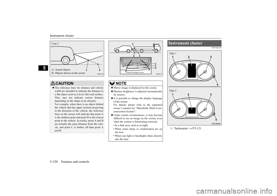
CAUTION The reference lines for
distance and vehicle
width are intended to i
ndicate the distance to
a flat object such as a level, flat road surface. They may not indicate correct distance depending on the shape of an obstacle.For example, when there is an object behind the vehicle that has u
pper sections projecting
in the direction of the
vehicle, the reference
lines on the screen will
indicate that point A
is the farthest point an
d point B is the closest
point to the vehicle. In
reality, point A and B
are actually the same distance from the vehi- cle, and point C is fa
rther off than point A
and B.Case 2 A- Actual objects B- Objects shown on the screen
NOTE
Mirror image is displayed on the screen. Monitor brightness is adjusted automatically by sensors. It is possible to change the display language of the screen. For details, please refer to the separatedowner’s manual for “Mitsubishi Multi-Com- munication System”. Under certain circumst
ances, it may become
difficult to see an image on the screen, even when the system is functioning correctly. • In a dark area, such as at night. • When water drops or
condensation are on
the lens. • When sun light or he
adlights shine directly
into the lens.
Instrument cluster 1- Tachometer
P.5-121
Type 1 Type 2
BK0211800US.book 120 ページ 2014年3月12日 水曜日 午後2時42分
Page 198 of 446
Instrument cluster
Features and controls 5-121
5
N00519101272
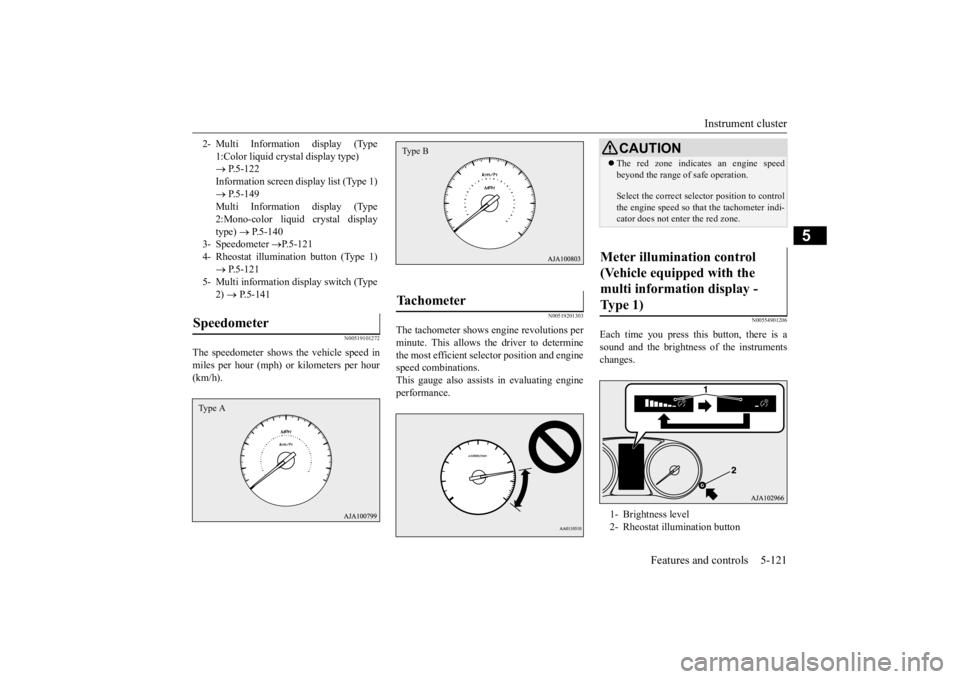
The speedometer shows the vehicle speed in miles per hour (mph) or kilometers per hour(km/h).
N00519201303
The tachometer shows e
ngine revolutions per
minute. This allows the driver to determine the most efficient sele
ctor position and engine
speed combinations.This gauge also assists in evaluating engine performance.
N00554901206
Each time you press this button, there is asound and the brightness
of the instruments
changes.
2- Multi Information display (Type
1:Color liquid crystal display type) P.5-122 Information screen display list (Type 1) P.5-149 Multi Information display (Type2:Mono-color liquid crystal display type)
P.5-140
3- Speedometer
P.5-121
4- Rheostat illumina
tion button (Type 1)
P.5-121
5- Multi information display switch (Type
2) P.5-141
Speedometer Type A
Tachometer Type B
CAUTIONThe red zone indicates an engine speed beyond the range of safe operation. Select the correct select
or position to control
the engine speed so that
the tachometer indi-
cator does not enter the red zone.
Meter illumination control (Vehicle equipped with the multi information display - Type 1) 1- Brightness level 2- Rheostat illumination button
BK0211800US.book 121 ページ 2014年3月12日 水曜日 午後2時42分
Page 199 of 446
Multi Information display - Type 1 5-122 Features and controls
5
N00555001334
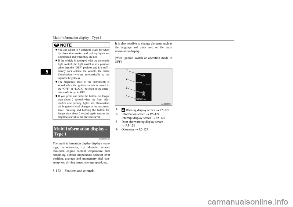
The multi information display displays warn- ings, the odometer, trip odometer, servicereminder, engine cool
ant temperature, fuel
remaining, outside temper
ature, selector lever
position, average and momentary fuel con-sumption, driving range, average speed, etc.
It is also possible to change elements such as the language and units used on the multiinformation display. [With ignition switch
or operation mode in
OFF]
NOTE
You can adjust to 8 different levels for when the front side-marker
and parking lights are
illuminated and when they are not. If the vehicle is equipped with the automatic light control, the light
switch is in a position
other than the “OFF” pos
ition and it is suffi-
ciently dark outside the vehicle, the meter illumination switches automatically to theadjusted brightness. The brightness level
of the instruments is
stored when the ignition switch is turned to the “OFF” or “LOCK”
position or the opera-
tion mode is put in OFF. If you press and hold the button for longer than about 2 second when the front side-marker and parking li
ghts are illuminated,
the brightness level changes to the maximum level. Pressing and holding the button forlonger than about 2 second again returns the brightness level to
the previous level.
Multi Information display - Type 1
1-
Warning display screen
P.5-128
2- Information screen
P.5-124
Interrupt display screen
P.5-127
3- Door ajar warning display screen
P.5-128
4- Odometer
P.5-129
BK0211800US.book 122 ページ 2014年3月12日 水曜日 午後2時42分
Page 200 of 446
![MITSUBISHI OUTLANDER III 2015 Owners Manual Multi Information display - Type 1
Features and controls 5-123
5
[With ignition switch or operation mode in ON]
N00555101188
Each time the multi information display switch is operated, th
e buzzer s](/manual-img/19/58145/w960_58145-199.png "MITSUBISHI OUTLANDER III 2015 Owners Manual Multi Information display - Type 1
Features and controls 5-123
5
[With ignition switch or operation mode in ON]
N00555101188
Each time the multi information display switch is operated, th
e buzzer s")
Multi Information display - Type 1
Features and controls 5-123
5
[With ignition switch or operation mode in ON]
N00555101188
Each time the multi information display switch is operated, th
e buzzer sounds and the
multi information disp
lay changes between
information such as warnings, trip odometer,
1- Drive mode indicator display screen (if
so equipped)
P. 5 - 7 6
2- S-AWC control mode display screen (if
so equipped)
P. 5 - 7 9
3-
Warning display screen
P.5-128
4- Forward Collision Mitigation System
(FCM) OFF displa
y screen (if so
equipped)
P.5-106
5- Lane Departure Warning (LDW) dis-
play screen (if so equipped)
P. 5 - 1 1 1
6- ECO mode indicator display screen
P.5-177
7- Information screen
P.5-124
8- Selector lever
position display
P.5-62, 5-69
9- Engine coolant te
mperature display
P.5-128
10- Odometer
P.5-129
11- Cruise control display screen (if so
equipped)
P.5-92
12- Adaptive Cruise Control System (ACC)
display screen (if so equipped) P.5-96
13- ECO indicator (if so equipped)
P.5-133
14- Fuel remaining display screen
P.5-129
15- Outside temperature display screen
P.5-129
NOTE
The fuel units, outside
temperature units,
display language, and
other settings can be
changed. Refer to “Changing the function settings” onpage 5-134.
Multi information display switch
BK0211800US.book 123 ページ 2014年3月12日 水曜日 午後2時42分
Page 201 of 446
Multi Information display - Type 1 5-124 Features and controls
5
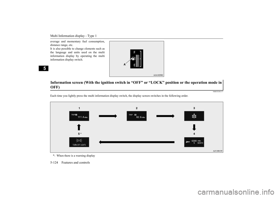
average and momentary fuel consumption, distance range, etc.It is also possible to change elements such as the language and units used on the multi information display by operating the multiinformation display switch.
N00555301177
Each time you lightly press th
e multi information display switch, the displa
y screen switches in the following order.
Information screen (With the igniti
on switch in “OFF” or “LOCK” po
sition or the operation mode in
OFF) *: When there is a warning display
BK0211800US.book 124 ページ 2014年3月12日 水曜日 午後2時42分
Page 202 of 446
Multi Information display - Type 1
Features and controls 5-125
5
N00555801202
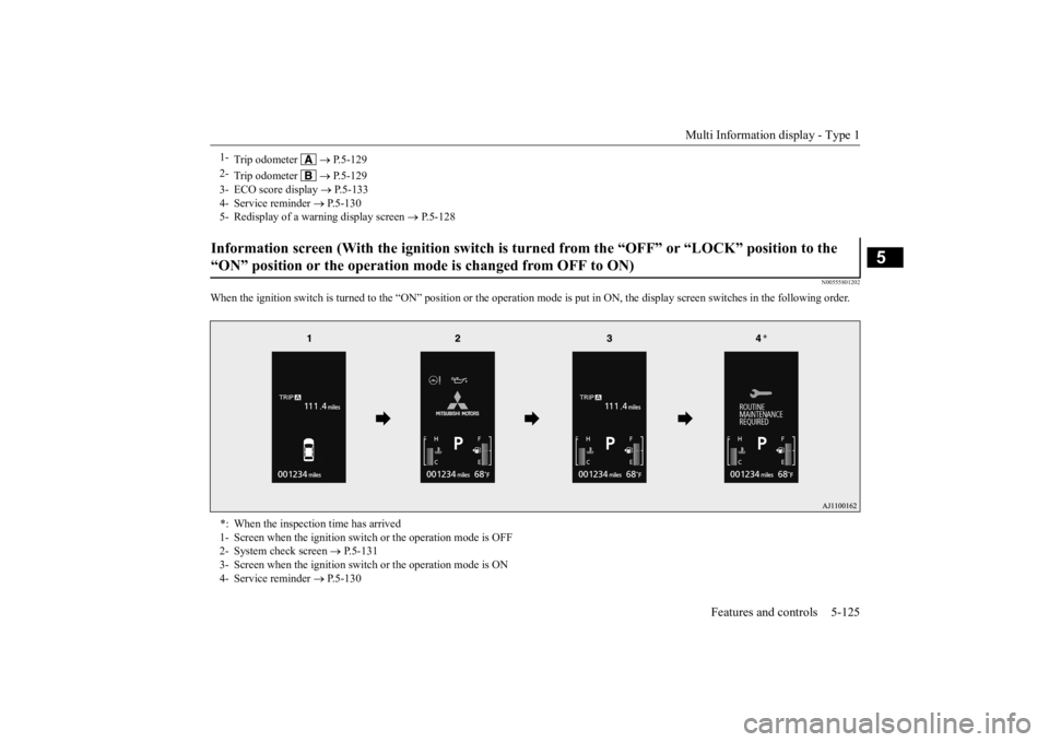
When the ignition switch is turned to the
“ON” position or the operation m
ode is put in ON, the disp
lay screen switches in the
following order.
1-
Trip odometer
P.5-129
2-
Trip odometer
P.5-129
3- ECO score display
P.5-133
4- Service reminder
P.5-130
5- Redisplay of a warning display screen
P.5-128
Information screen (With the igniti
on switch is turned from the “O
FF” or “LOCK” position to the
“ON” position or the operation mo
de is changed from OFF to ON)
*: When the inspection time has arrived 1- Screen when the ignition switch
or the operation mode is OFF
2- System check screen
P.5-131
3- Screen when the ignition switch
or the operation mode is ON
4- Service reminder
P.5-130
BK0211800US.book 125 ページ 2014年3月12日 水曜日 午後2時42分