2015 MERCEDES-BENZ SLS AMG GT ROADSTER stop start
[x] Cancel search: stop startPage 216 of 290
also read th
eoperatin ginstruction sfor the
garag edoor system.
X Select ke yposition 2wit hthe Start/Stop
button.
X Press button 0044,0087or0085 whic hyou have
programed to operate th egarag edoor.
Garage door system wit hafixed code: indi-
cator lamp 0043light supg reen.
Garage door system wit harolling code:
indicator lamp 0043flashes green.
i The transmitte
rwill transmit asignal as
lon gast hebutto nisp ressed. The trans-
mission is halted after amaximum of ten
seconds and indicator lamp 0043light sup
yellow. Press button 0044,0087or0085 again if
necessary.
Clearing th ememory X
Select ke yposition 2wit hthe Start/Stop
button.
X Press buttons 0044and 0085.
The indicator lamp light supyellow.
X Press and hold buttons 0044and 0085until the
indicator lamp turns green.
i Mak
esure that you clear th ememory of
th ei ntegrate dgarag edoor opener before
sellin gthe vehicle. Charg
emaintenance socket
The battery may drain if th evehicle is left sta-
tionar yfor lon gperiods. In this case,
Mercedes-Ben zrecommends attaching the
trickle charge rtothecharge maintenance
socket.
The charge maintenance socke tisdesigned
solely for connecting atrickle charger. A
trickle charge rcan be obtaine dfroman
authorized Mercedes-Ben zCenter, for exam-
ple. X
Switch th eignition off.
X Open th etrunk lid.
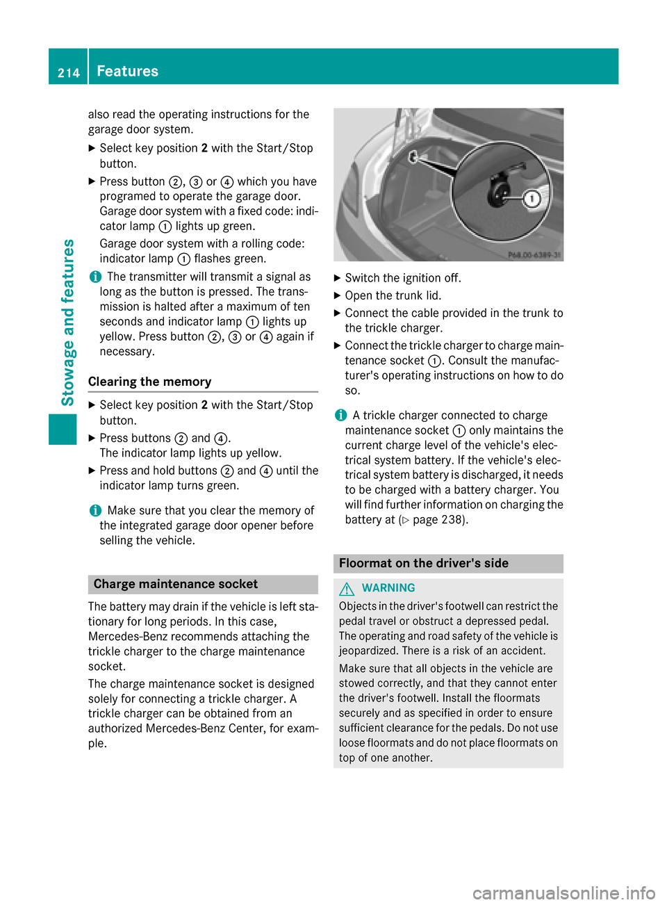
X Connect th ecabl ep rovide dinthetrunk to
th et rickle charger.
X Connect th etrickle charge rtocharge main-
tenance socket 0043.Consult th emanufac-
turer' soperatin ginstruction sonhow to do
so.
i At
rickle charge rconnected to charge
maintenance socket 0043only maintain sthe
curren tcharge leve lofthevehicle's elec-
trical system battery. If th evehicle's elec-
trical system battery is discharged, it needs
to be charge dwithab attery charger. You
will fin dfurther informatio nonchargin gthe
battery at (Y page 238). Floorma
tonthedriver's side G
WARNING
Object sinthedriver' sfootwell can restrict the
pedal travel or obstruc tadepressed pedal.
The operatin gand road safety of th evehicle is
jeopardized. Ther eisariskofana ccident.
Mak esure that all object sinthevehicle are
stowed correctly, and that they canno tenter
th ed river' sfootwell. Install th efloormats
securely and as specifie dinorder to ensure
sufficient clearance for th epedals .Don otuse
loos efloormats and do no tplac efloormats on
to pofo neanother. 214
FeaturesStowage and features
Page 222 of 290
X
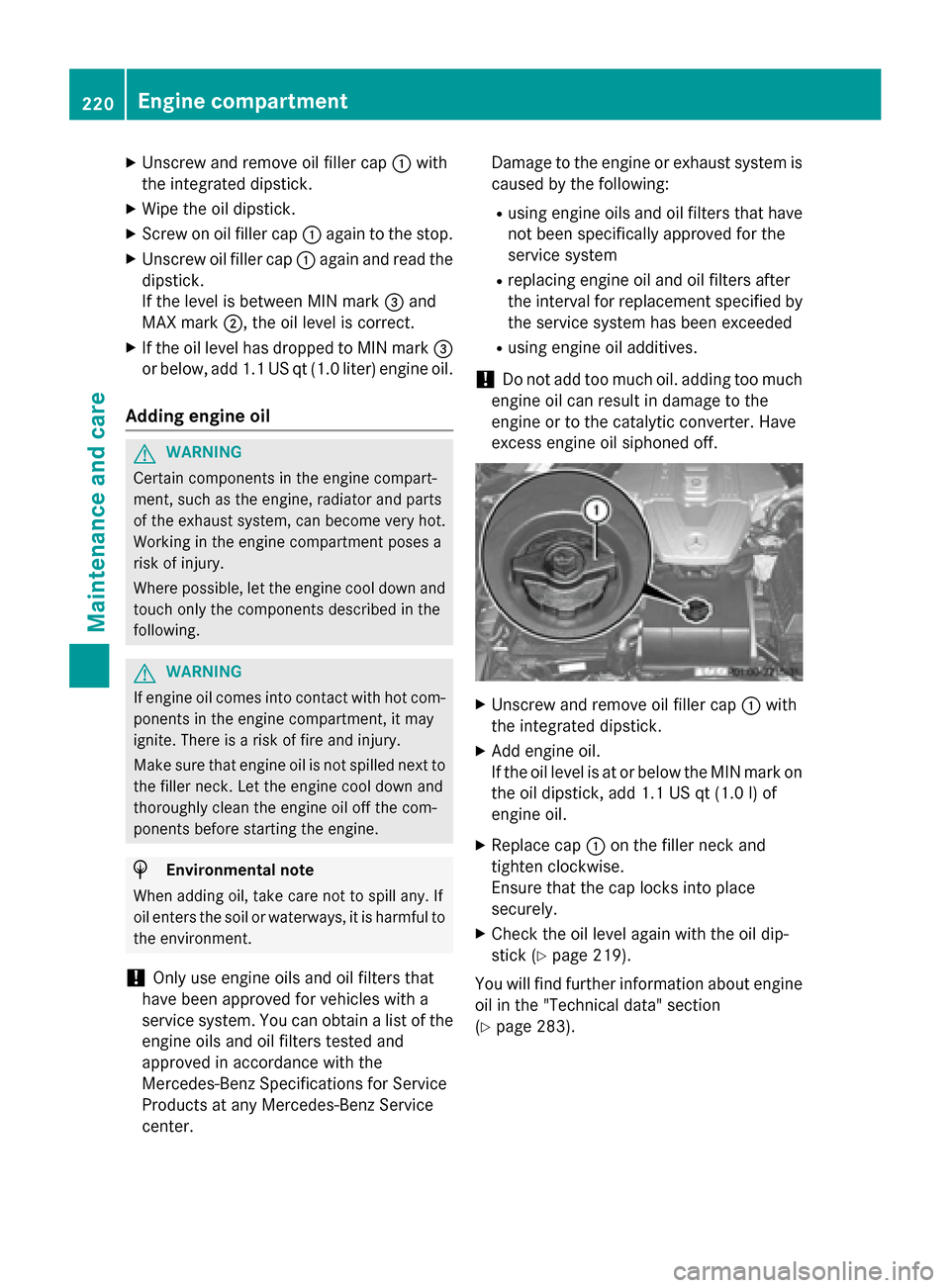
Unscrew and remove oil filler cap 0043with
the integrated dipstick.
X Wipe the oil dipstick.
X Screw on oil filler cap 0043againtot he stop.
X Unscrew oil filler cap 0043againa nd read the
dipstick.
If the level is between MIN mark 0087and
MAX mark 0044,the oil level is correct.
X If the oil level has dropped to MIN mark 0087
or below,a dd 1.1 US qt (1. 0liter )engine oil.
Adding engineo ilG
WARNING
Certain componentsint he engine compart-
ment, such as the engine, radiator and parts
of the exhaust system, can become very hot.
Working in the engine compartment poses a
risk of injury.
Where possible,l et the engine cool down and
touch only the componentsd escribed in the
following. G
WARNING
If engine oil comes into contact with hot com- ponents in the engine compartment,itm ay
ignite. There is arisk of fire and injury.
Make sure that engine oil is not spilledn ext to
the filler neck. Let the engine cool down and
thoroughly clean the engine oil off the com-
ponents before starting the engine. H
Environmental note
When adding oil, take care not to spill any. If
oil enters the soil or waterways, it is harmful to the environment.
! Only use engine oils and oil filters that
have been approved for vehicles with a
service system. You can obtain alist of the
engine oils and oil filters tested and
approved in accordance with the
Mercedes-Benz Specifications for Service
Products at any Mercedes-Benz Service
center. Damage to the engine or exhaust system is
caused by the following:
R using engine oils and oil filters that have
not been specificallya pproved for the
service system
R replacing engine oil and oil filters after
the interval for replacement specified by
the service system has been exceeded
R using engine oil additives.
! Do not add too much oil. adding too much
engine oil can result in damage to the
engine or to the catalytic converter. Have
excess engine oil siphoned off. X
Unscrew and remove oil filler cap 0043with
the integrated dipstick.
X Add engine oil.
If the oil level is at or below the MIN mark on
the oil dipstick, add 1.1 US qt (1.0 l)of
engine oil.
X Replace cap 0043on the filler neck and
tighten clockwise.
Ensure that the cap locks into place
securely.
X Check the oil level again with the oil dip-
stick (Y page 219).
You will find further information about engine
oil in the "Technical data" section
(Y page 283). 220
Engine compartmentMaintenance and care
Page 226 of 290
You can wash the vehicle in an automatic car
wash fro mthe very start.
If the vehicle is very dirty, pre-wash it before
cleaning it in an automatic car wash.
! Never clean your vehicle in
aTouchless
Automatic Car Wash as these use special
cleaning agents. These cleaning agent scan
damage the paintwork or plastic parts.
! When washing your vehicle in
atow-
through car wash, use the SmartKey
instead of the Start/Stop button.
Start the engin eusing the SmartKey.. Move
the transmission to Nwith the E-SELECT
lever .Use the SmartKey to switc hthe
engin eoff again and the nturn the Smart-
Key to position 2.Make sure that you then
leave the SmartKey in position 2.You may
otherwise damage the vehicle, the trans-
missio northe car wash.
Check the transmission position in the
instrumen tcluster.
! Use the E‑SELECT lever to shift the trans-
missio ntoNbefore switching the engine
off .Ify ou open the driver's or front-
passenger door, the transmission remains
in this position for up to 30 minutes if the
SmartKey is in the ignition, even if the
engin eisswitched off .Ifyou do not shift the
transmission to Nusing the E‑SELECT lever
beforehand, it shift sautomatically to park-
ing position Pand lock sthe wheels if the
driver's or front-passenge rdoor is opened
and the engin eisswitched off .This may
damage the vehicle, the transmission or
the car wash.
Observe the information on maneuvering
(Y page 131). !
Before drivin
gintoana utomatic car wash,
make sure that it is suitable for the dimen- sion soft he vehicle. In particular, make
sure that:
R there is enough groun dclearance
betwee nthe vehicle underbody and the
guide rails of the automatic car wash.
R the clearance width of the automatic car
wash is sufficient ,particularly the width
of the guide rails.
R you enter the automatic car wash
straight and in the center of the guide
rails in order to avoid damagin gthe tires
or wheel rims.
Fold in the exterior mirrors befor ethe vehi-
cle is washed. The exterior mirrors could
otherwise be damaged.
! Make sure that:
R the side windows and the roof are com-
pletely closed
R the climat econtrol blower is switched off
R the windshield wiper switc hisatposition
0
The vehicle could otherwise be damaged.
! In portal car washes, the windshield wip-
ers may be move dupthe windshield by the
cleaning brushes when the ignition is
switched off.
Set the Start/Stop button to key position 2
to reset the windshield wipers to their orig-
inal position.
! Preferably use automatic car washes with
adjustable high-pressure pre-cleaning. This corresponds with the specification for the
Cabriolet program. In car washes that use
high water pressures, there is arisk that a
small amount of water may leak int othe
vehicle.
! Cabriolet:
do not treat the vehicle with
hot wax under any circumstances.
After using an automatic car wash, wipe off
wax and drying agent sfromt he windshield
and the wiper blades. This will prevent smears 224
CareMaintenance and care
Page 230 of 290
!
Do not clean wiper blades too often and
do not rub them too hard. Otherwise, the
graphite coating could be damaged. This
could cause wiper noise.
X Switch off the engine.
X Remove your foot from the brake pedal.
X Set the windshieldw iper to the00AAposi-
tion on the combination switch.
X Press the Start/Stop button repeatedly
until the windshieldw iper starts.
X When the wiper arms have reached aver-
tical position, press the Start/Stop button.
X Fold the wiper arm awayf rom the wind-
shield until it engages.
X Set the wiper bladeatr ight angles to the
wiper arm.
X Carefully clean the wiper blades with a
damp cloth.
X Fold the windshieldw iper arms back again
before switching on the ignition.
! Hold the wiper arm securely when folding
back. The windshieldc ould be damagedif
the wiper arm smacks against it suddenly.
Cleaning the exterior lighting X
Cleant he plastic lenses of the exterior
lighting using awet sponge and amild
cleaning agent, e.g. Mercedes-Benz car
shampoo or cleaning cloths.
! Only use cleaning agents or cleaning
cloths which are suitablef or plastic light
lenses. Unsuitable cleaning agents or
cleaning cloths could scratch or damage
the plastic light lenses.
Cleaning the mirror turns ignals!
Only use cleaning agents or cleaning
cloths that are suitablef or plastic lenses.
Unsuitable cleaning agents or cleaning
cloths could scratch or damage the plastic
lenses of the mirror turn signals.
X Cleant he plastic lenses of the mirror turn
signals in the exterior mirror housing using aw
et sponge and amild cleaning agent,
e.g. Mercedes-Benz car shampoo or clean-
ing cloths.
Cleaning the sensors !
If you clean the sensors with
apower
washer, make sure that you keep adis-
tance of at least 11.8 in (30 cm) between
the vehicle and the power washer nozzle.
Information aboutt he correct distance is
available from the equipment manufac-
turer. X
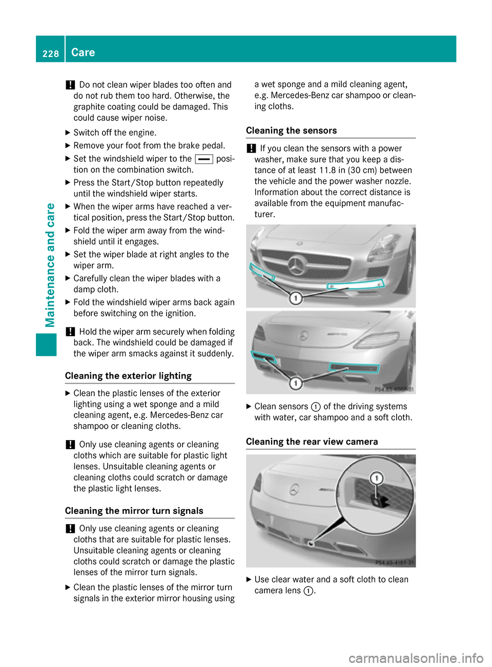
Cleans ensors0043of the driving systems
with water, car shampoo and asoft cloth.
Cleaning the rear view camera X
Use clear water and asoft cloth to clean
camera lens 0043.228
CareMaintenance and care
Page 238 of 290
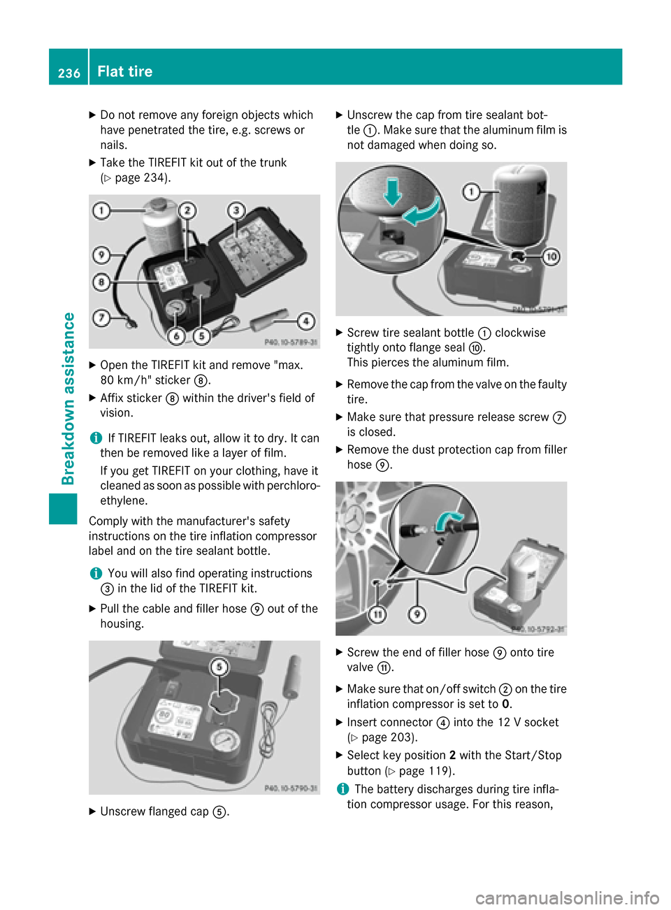
X
Do not remove any foreign objects which
have penetrated the tire, e.g .screws or
nails.
X Take the TIREFIT kit ou tofthe trunk
(Y page 234). X
Open the TIREFIT kit and remove "max.
80 km/h" sticker 006C.
X Affi xsticker 006Cwithi nthe driver's field of
vision.
i If TIREFIT leaks out, allo
wittodry.Itc an
the nberemove dlikeal ayer of film.
If yo ugetTIREFIT on your clothing, have it
cleane dassoona spossibl ewithp erchloro-
ethylene.
Compl ywitht he manufacturer's safety
instructions on the tir einflatio ncompressor
labe land on the tir esealan tbottle.
i Yo
uw illa lsof indo perating instructions
0087 in the li dofthe TIREFIT kit.
X Pull the cable and fille rhose 006Doutoft he
housing. X
Unscrew flange dcap 0083. X
Unscrew the cap fro mtires ealan tbot-
tle 0043.M akes uret hatthe aluminu mfilmis
not damage dwhend oing so. X
Scre wtires ealan tbottle 0043 clockwise
tightl yonto flange seal 006E.
This pierces the aluminu mfilm.
X Remov ethe cap fro mthe valv eonthe faulty
tire.
X Make sure tha tpressure release screw 006B
is closed.
X Remov ethe dust protection cap fro mfiller
hose 006D. X
Scre wthe end of fille rhose 006Donto tire
valve 006F.
X Make sure tha ton/off switch 0044on the tire
inflatio ncompressor is se tto0.
X Insert connector 0085into the 12 Vsocket
(Y page 203).
X Select key position 2with the Start/Stop
button (Y page 119).
i Th
eb attery discharge sdurin gtirei nfla-
tio nc ompressor usage. For thi sreason, 236
Flat tireBreakdow
nassistance
Page 246 of 290
X
First, remove the jumper cable sfrom earth point 0085and negative terminal 0087,then from
positiv eclamp 0043and positiv eterminal 0044.Each time beginning with your vehicle' sbattery.
X Slide cover 0083of the positiv eterminal in the opposite directio ntothe arrow.
X Have the battery checke dataqualified specialist workshop.
i Jump-starting is not considered to be
anorma loperating condition.
i Jumpe
rcable sand further information regarding jump-starting can be obtained at any
qualified specialist workshop. Towing and tow-starting
Important safety notes
G
WARNING
The rea raxlel ocks when:
R the engine is not running
R the engine stalls while the vehicle is being
towed
R there is amalfunction in the power supply
or the vehicle' selectrica lsystem
There is ariskofana ccident.
In the event of abreakdown, yo ushould
always hav ethe vehicle transported. G
WARNING
If the brake system or power steering is mal-
functioning and your vehicle is then towed
away ,significantly more effort may be
required to stee rand brake than is normally
required .There is ariskofana ccident.
In such cases, use atow bar. Befor etowing,
make sur ethat the steering move sfreely. G
WARNING
If the weigh tofthe vehicle to be towe dortow-
starte disgreater than the permissible gross
weigh tofyourv ehicle:
R the towing ey ecould detach itself
R the vehicle/trailer combinatio ncould roll-
over.
There is ariskofana ccident.
Whe ntowing or tow-starting another vehicle,
its weigh tshoul dnot be greater than the per-
missible gros sweigh tofy ourv ehicle. !
Use the SmartKe
yinstead of the Start/
Stop button whe ntowing the vehicle.
Start the engine and keep it running. Turn
the SmartKe ytoposition 2in the ignition.
Set the transmission to Nusing the E-
SELECT lever. Make sure that yo uthen
leave the SmartKe yinposition 2.
Check the transmission positio ninthe
instrument cluster.
! Make sure that the electric parking brake
is released .Ifthe electric parking brake is
faulty ,visit aquali fied specialist workshop.
Mercedes-Benz recommends that yo uuse
an authorized Mercedes-Benz Center for
this purpose.
! Whe
ntowing, pull away slowl yand
smoothly .Ifthe tractive power is too high,
the vehicles could be damaged.
! Only secure the tow rope or tow ba
ratthe
towing eyes. Otherwise, the vehicle could
be damaged.
! Do not us
ethe towing eyes for recovery
purposes as this could damag ethe vehicle.
If in doubt, recover the vehicle with acrane.
! The vehicle can be towe
damaximum of
30 miles (50km). The towing speed of
30 mph (50 km/h )mustn ot be exceeded.
If the vehicle ha stobetowedmore than
30 miles (50km), the entire vehicle mus tbe
raised and transported.
! Do not tow with sling-typ
eequipment.
Thi scould damag ethe vehicle. 244
Towinga
nd tow-startingBreakdow nassistance
Page 248 of 290
X
Switch on the hazard warning lamps
(Y page 98).
X Make sure tha tthe SmartKey is in position
2 in the ignition and tha tthe engine is run-
ning throughout the towing procedure.
X Mov ethe transmissio ntoNwith the E-
SELECT lever. Check the transmissio nposi-
tion in the instrument cluster. Towin
gavehicle with both axles on
the ground
It is important tha tyou observe the safety
instructions when towing away your vehicle
(Y page 244).
X Switch on the hazard warning lamps
(Y page 98).
i Whe
ntowing with the hazard warning
flashers switche don, us ethe combination
switch as usua ltosignal in which direction
yo ua re changing. In this case, onl ythe
indicator lamps for the direction of travel
flash. Whe nyou reset the combination
switch, the hazard warning flashers start
flashing again.
X Insert the SmartKey into the ignition lock
(Y page 119).
X Start the engine and leave the SmartKey in
the ignition.
X Mov ethe transmissio ntoNwith the E-
SELECT lever.
X Check the transmissio nposition in the
instrument cluster display (Y page 123).
X Leave the engine running throughout the
entir etowing procedure Transporting the vehicle
The towing ey ecan be used to pull the vehicle
onto atraile rort ransporter for transporting
purposes.
! Yo
um ay onl ysecure the vehicl ebythe
wheels, not by parts of the vehicl esuchas axl
eors teering components .Otherwise,
the vehicl ecould be damaged.
X Start the engine.
X Make sure tha tthe SmartKey is in position
2 in the ignition and tha tthe engine is run-
ning during the entir eloadin goperation.
X Mov ethe transmissio ntoNwith the E-
SELECT lever. Check the transmissio nposi-
tion in the instrument cluster.
As soon as the vehicle has been loaded: X Prevent the vehicl efrom rolling away by
applying the electri cparking brake.
X Shift the transmissio ntoPwith the button
in the center console.
X Turn the SmartKey to position 0in the igni-
tion lock and remove the SmartKey from
the ignition lock.
X Secure the vehicle. Fuses
Important safety notes
G
WARNING
If yo umanipulate or bridge afaulty fus eorif
yo ur eplace it with afusew ithah ighe ramper-
age, the electri ccable scould be overloaded.
Thi scould resul tinafire. There is ariskofan
accident and injury.
Alway sreplace faulty fuses with the specified
new fuses having the correct amperage.
! Only us
efuses tha thaveb eena pproved
for Mercedes-Benz vehicles and which
have the correct fus erating for the system
concerned. Otherwise, components or sys-
tems could be damaged.
The fuses in your vehicl eserve to close down
faulty circuits. If afuseb lows ,allthe compo-
nents on the circuit and thei rfunctions stop
operating.
Blown fuses mus tbereplaced with fuses of
the same rating, which yo ucan recognize by 246
FusesBreakdown assistance
Page 259 of 290
monitor only functions if the correct sensors
are installed on all wheels.
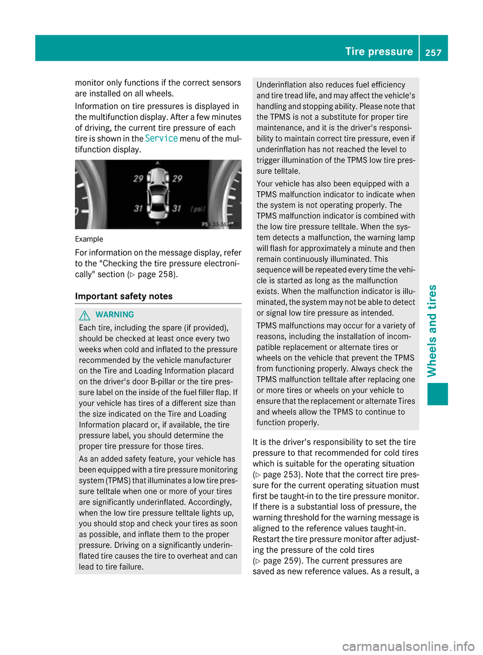
Information on tire pressures is displayed in
the multifunction display.A fterafew minutes
of driving, the current tire pressure of each
tire is show nintheService Service menu of the mul-
tifunction display. Example
For informatio nonthe message display,r efer
to the "Checking the tire pressure electroni-
cally" section (Y page258).
Important safety notes G
WARNING
Each tire, including the spare (if provided),
should be checked at least once every two
weeks when cold and inflated to the pressure recommended by the vehicl emanufacturer
on the Tire and Loading Information placard
on the driver' sdoor B-pillar or the tire pres-
sure label on the inside of the fuel filler flap .If
yourv ehiclehas tires of adifferent size than
the size indicated on the Tire and Loading
Information placard or, if available, the tire
pressure label, you should determine the
prope rtire pressure for those tires.
As an added safety feature ,you rv ehicl ehas
been equippe dwithatire pressure monitoring
system (TPMS) that illuminates alow tire pres-
sure telltal ewhen one or more of yourt ires
are significantly underinflated. Accordingly,
when the low tire pressure telltal elights up,
you should stop and check yourt ires as soon
as possible, and inflate them to the proper
pressure. Driving on asignificantly underin-
flated tire cause sthe tire to overhea tand can
leadtot ire failure. Underinflation alsor
educes fuel efficiency
and tire tread life ,and may affect the vehicle's
handling and stopping ability .Please note that
the TPMS is not asubstitute for prope rtire
maintenance, and it is the driver' sresponsi-
bility to maintai ncorrect tire pressure, even if
underinflation has not reache dthe level to
trigger illumination of the TPMS low tire pres-
sure telltale.
Yourv ehiclehas alsob een equippe dwith a
TPMS malfunction indicator to indicate when
the system is not operating properly. The
TPMS malfunction indicator is combined with
the low tire pressure telltale. When the sys-
tem detects amalfunction, the warning lamp
willf lashf or approximatel yaminute and then
remai ncontinuously illuminated. This
sequence willber epeated every time the vehi-
cle is started as long as the malfunction
exists. When the malfunction indicator is illu-
minated, the system may not be abletod etect
or signa llow tire pressure as intended.
TPMS malfunctions may occur for avariety of
reasons, including the installation of incom-
patible replacement or alternate tires or
wheels on the vehicl ethat prevent the TPMS
from functioning properly. Always check the
TPMS malfunction telltal eafter replacing one
or more tires or wheels on yourv ehicleto
ensure that the replacement or alternate Tires
and wheels allow the TPMS to continue to
function properly.
It is the driver' sresponsibility to set the tire
pressure to that recommended for cold tires
which is suitable for the operating situation
(Y page2 53).Note that the correct tire pres-
sure for the current operating situation must
first be taught-in to the tire pressure monitor.
If there is asubstantial loss of pressure, the
warning threshol dfor the warning message is
aligned to the reference values taught-in.
Restart the tire pressure monitor after adjust-
ing the pressure of the cold tires
(Y page2 59).The current pressures are
saved as new reference values. As aresult, a Tire pressure
257Wheelsand tires Z