2015 MERCEDES-BENZ SLS AMG GT COUPE change time
[x] Cancel search: change timePage 261 of 290

Tire pressure monito
rwarning mes-
sages If the tire pressure monitor detects
apressure
loss in one or mor etires, awarnin gm essage
is shown in the multifunctio ndisplay and the
yellow tire pressure monitor warnin glamp
come son.
R If the Correc tTireP ressure
Correc tTireP ressure message
appear sinthe multifunctio ndisplay ,the
tire pressure in at leas tone tire is too low
and must be correcte datthe next oppor-
tunity.
R If the Check Tir ePressure
Check Tir ePressure message
appear sinthe multifunctio ndisplay ,the
tire pressure in one or mor etire sh asdrop-
pe ds ignificantl yand the tire smustbe
checked.
R If the TirePressure Warnin gTire
Tir ePressure Warnin gTire
Malfunction
Malfunction message appear sinthe mul-
tifunctio ndisplay ,the tire pressure in one
or mor etire sh asdropped suddenl yand the
tire sm ustbec hecked.
Observe the instructions and safety note sin
the displa ymessage sinthe "Tires" section
(Y page 182).
i If the whee
lposit ions on the vehicl eare
rotated ,the tire pressures ma ybedis-
played for the wrong positions for ashort
time .Thisisr ectifie dafter afew minute sof
driving ,and the tire pressures ar edisplayed
for the correct positions.
Restartin gthe tire pressure monitor When yo
urestar tthe tire pressure monitor, all
existing warnin gmessage saredeleted and
the warnin glam ps go out. The monitor uses
the currentl yset tire pressures as the refer-
ence values for monitoring. In mos tcases, the
tire pressure monitor will automatically
detect the new reference values after you
have change dthe tire pressure. However, you
can also define reference values manuall yas
describe dhere. The tire pressure monitor
then monitors the new tire pressure values. X
Set the tire pressure to the valu erecom-
mended for the corresponding driving sit-
uatio nont he Tire and Loading Information
placard on the driver's side
B-pillar (Y page 253).
Additiona ltire pressure values for different
load scan also be found on the tire pressure
table on the insid eofthe fuel fille rflap
(Y page 253).
X Make sure tha tthe tire pressure is correct
on al lfou rw heels.
X Make sure tha tthe SmartKe yisinposition
2 in the ignition lock.
X Press the 0059or0065 button on the steer-
ing whee ltoselect theServ.
Serv. menu.
X Press the 0063or0064 button to select
Tir ePressure
Tir ePressure.
X Press the 0076button.
The multifunctio ndisplay shows the cur-
rent tire pressure for the individual tire sor
the Tire Tire pressure
pressure will
willbe
bedisplayed
displayed
after drivin gafew minutes
after drivin gafew minutes mes-
sage.
X Press the 0064button.
The Use Curren tPressures as New
Use Curren tPressures as New
Reference Values
Reference Values message appearsin
the multifunctio ndisplay.
If yo uwishtoc onfirm the restart:
X Press the 0076button.
The TirePress. Monito rRestarted
Tir ePress. Monito rRestarted
message appear sinthe multifunctio ndis-
play.
After driving for afew minutes, the system
checks whether the current tire pressures
ar ew ithi nt he specifie drange.The new tire
pressures ar ethena ccepted as reference
values and monitored.
If yo uwishtoc ancel the restart:
X Press the 0038button.
The tire pressure values stored at the last
restar twillc ontinue to be monitored. Tire pressure
259Wheelsand tires Z
Page 272 of 290

the curb weight and the weight of the acces-
sories.
TIN (Tire Identificatio nNumber)
This is auniqu eide ntifier which can be used
by atirem anufacturer to identify tires ,for
exampl efor ap roduct recall, and thu side ntify
the purchasers. Th eTIN is made up of the
manufacturer's identity code, tir esize, tire
typ ecodea nd the manufacturing date.
Load bearin gind ex
Th eloa db eari ng index (als oloa dindex) is a
cod etha tcontains the maximum load bearing
capacity of atire.
Traction
Tractio nist he resul toffrictio nbetween the
tires and the roa dsurface.
Treadwea rind icators
This is indicated by narrow bars (treadwear
bars) tha tare distributed ove rthe tir etread. If
the tir etrea disl evel with the bars, the wear
limi tof 1
/ 16 in (1.
6mm) ha sbeenr eached.
Occupant distribution
Th ed istributio nofoccupants in avehicl eat
their designated seating positions.
Tota lloa dl im it
Rated cargo and luggag eloa dp lus68k ilo-
grams (15 0lb) times the vehicle' sdesig nated
seating capacity. Changin
gawheel Flat tire
Th e" Breakdown assistance" section
(Y page 235 )contains information and notes
on ho wtod ealw ithaf latt ire. Rotatin
gthe wheels G
WARNING
Interchanging the front and rea rwheel smay
severel yimpair the driving characteristics if
the wheels or tires have different dimensions. Th ew heel brakes or suspensio ncomponents
ma yalsobed amaged .The re is ariskofa cci-
dent.
Rotate front and rea rwheel sonlyift he wheels
and tires ar eofthe same dimensions.
! On vehicles equipped with
atirep ressure
monitor, electroni ccomponents are
locate dinthe wheel.
Tire-mounting tools shoul dnot be used
nea rthe valve. This could damage the elec-
troni ccomponents.
Onl yhavet ires change dataqualified spe-
cialist workshop.
Alway spayattentio ntothe instructions and
safety note swhenc hanging awheel
( Y page 271).
Th ew earp atterns on the front and rea rtires
differ, depending on the operating conditions.
Rotate the wheels befor eaclear wear pattern
ha sformed on the tires .Front tires typically
wear mor eonthe shoulders and the rea rtires
in the center.
If your vehicle' stirec onfiguration allows ,you
can change the wheels according to the inter-
vals in the tir emanufacturer's warranty book
in your vehicl edocum ents.Ifnow arranty
book is available, the tires shoul dberotated
every 3,000 to 6,000 mile s(5,000 to
10,000 km), or earlie riftirew earrequires .Do
not change the directio nofwheelrotation.
Clea nthe contact surfaces of the whee land
the brake disc thoroughly every tim eawheel
is rotated .Check the tir epressure and reac-
tivate the tir epressure monitor if necessary. Directio
nofrotation
Tires with aspecified directio nofrotation
have additional benefits, e.g .ifthere is arisk 270
Changin
gawheelWheels an dtires
Page 274 of 290

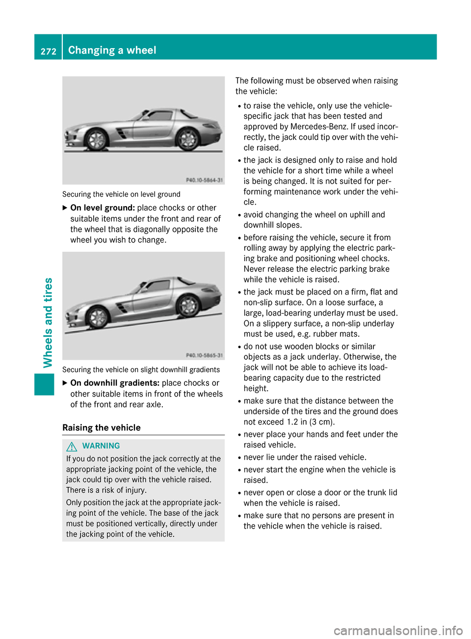
Securing the vehicle on level ground
X On level ground: place chocks or other
suitabl eitem sunder the front and rea rof
the wheel that is diagonall yopposite the
wheel yo uwishtoc hange. Securing the vehicle on slight downhil
lgradients
X On downhill gradients: place chocks or
othe rsuitabl eitem sinf ront of the wheels
of the front and rea raxle.
Raisin gthe vehicle G
WARNING
If yo udon ot position the jack correctly at the
appropriate jacking point of the vehicle ,the
jack could tip ove rwitht he vehicle raised.
There is ariskofi njury.
Only position the jack at the appropriate jack-
ing point of the vehicle .The base of the jack
mus tbep ositioned vertically ,directl yunder
the jacking point of the vehicle. The following mus
tbeo bserve dwhenr aising
the vehicle:
R to raise the vehicle ,only us ethe vehicle-
specifi cjack that ha sbeent ested and
approved by Mercedes-Benz. If used incor-
rectly, the jack could tip ove rwitht he vehi-
cle raised.
R the jack is designe donly to raise and hold
the vehicle for ashort time whil eawheel
is being changed .Itisnot suited for per-
forming maintenance work under the vehi-
cle.
R avoid changing the wheel on uphil land
downhil lslopes.
R before raising the vehicle ,secure it from
rolling away by applying the electri cpark-
ing brake and positioning wheel chocks.
Neve rrelease the electri cparking brake
whil ethe vehicle is raised.
R the jack mus tbep lace donaf irm,flata nd
non-slip surface. On aloose surface, a
large ,load-bearing underlay mus tbeu sed.
On aslippery surface, anon-slip underlay
mus tbeu sed, e.g. rubber mats.
R do not us ewoodenb locks or similar
objects as ajack underlay .Otherwise, the
jack will not be able to achieve its load-
bearing capacity du etothe restricted
height.
R make sure that the distance between the
underside of the tire sand the ground does
not excee d1.2 in (3 cm).
R never place your hands and fee tunder the
raised vehicle.
R never li eunder the raised vehicle.
R never star tthe engine when the vehicle is
raised.
R never ope norclosead oorort he trunk lid
when the vehicle is raised.
R make sure that no persons are present in
the vehicle when the vehicle is raised. 272
Changing
awheelWheels and tires
Page 282 of 290

Useful information
i This Operator's Manual describes all
models and all standard and optional equip- ment of your vehicle available at the time of
publication of the Operator's Manual.
Country-specific differences are possible.
Please not ethat your vehicle may not be
equipped with all feature sdescribed. This
also applies to safety-related system sand
functions.
i Please read the information on qualified
specialist workshops (Y page 23).Information regarding technical data
You can find technical data on the Interne tat:
http://www.mercedes-benz.com
i The data stated here specifically refer
sto
av ehicle with standard equipment .Consult
an authorized Mercedes-Benz Center for
the data for all vehicle variant sand trim
levels. Warranty
The Service and Warrant yInformation book-
let contains detailed information about the
warranties covering your vehicle.
Your authorized Mercedes-Benz Center will
exchange or repair any defective parts origi-
nally installed in the vehicle in accordance
with the terms of the following warranties:
R New Vehicle Limited Warranty
R Emission System Warranty
R Emission Performanc eWarranty
R California, Connecticut, Maine, Massachu-
setts, New York, Pennsylvania, Rhode
Island and Vermont Emission Control Sys-
tem Warranty
R State warrant yenforcement laws (Lemon
Laws) Replacemen
tparts and accessories are cov-
ered by the Mercedes-Benz Parts and Acces- sories warranties. You can obtain information about this from any authorized Mercedes-
Ben zCenter.
i Should you lose your Service and War-
rant yInformation booklet ,have an author-
ized Mercedes-Benz Center arrange for a
replacement.Itw ill be mailed to you. Identification plates
Vehicle identification plat
ewith vehi-
cle identification number (VIN) and
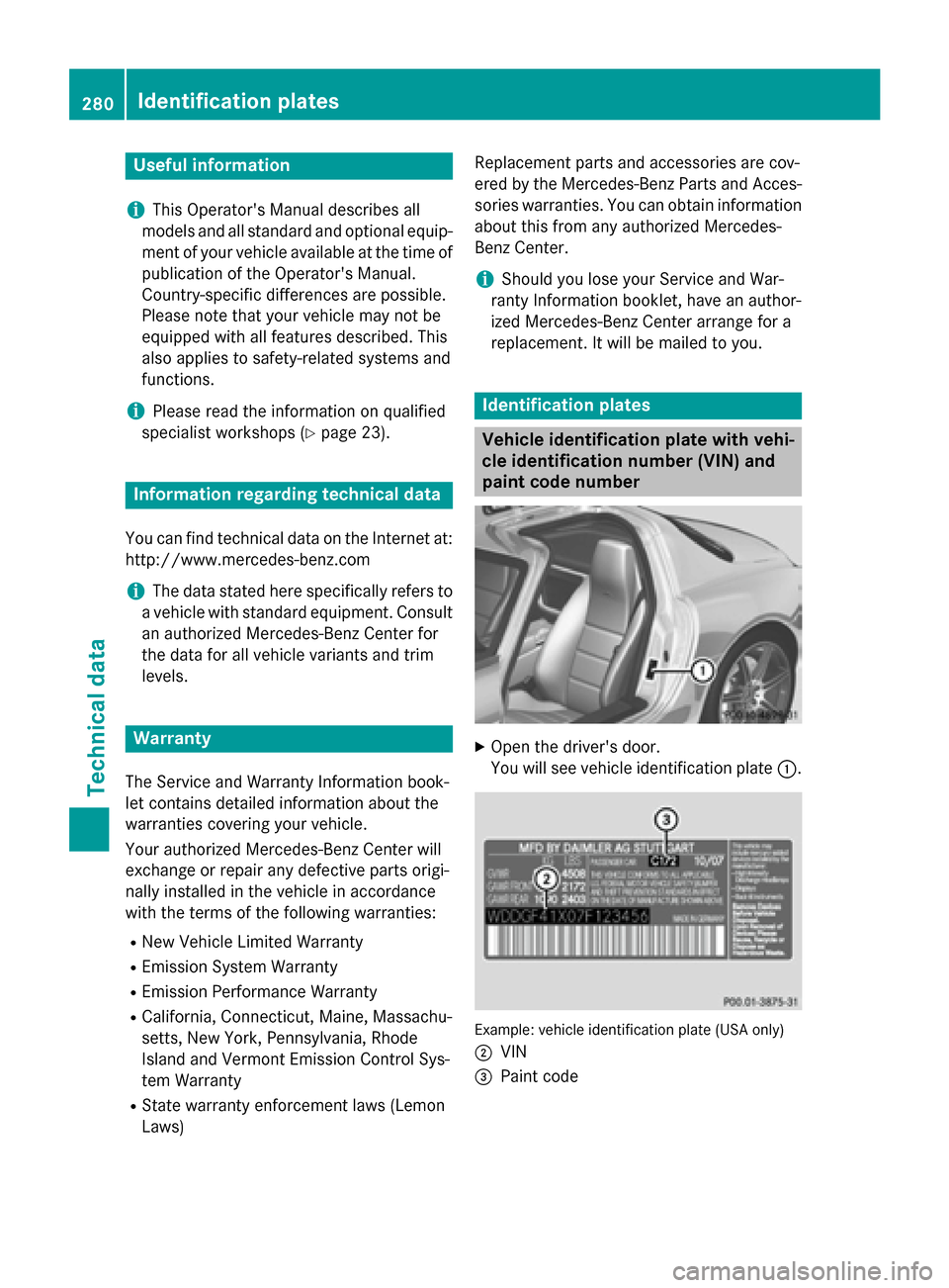
paint code number X
Open the driver' sdoor.
You will see vehicle identification plate 0043. Example: vehicle identification plate (USA only)
0044 VIN
0087 Paint code 280
Identification platesTechnical data