2015 MERCEDES-BENZ SLK-Class door lock
[x] Cancel search: door lockPage 270 of 358

R
USA: Mercedes-Benz Customer Assis-
tance Center at 1-800-FOR-MERCedes
(1-800-367-6372) or 1-866-990-9007
R Canada: Customer Service at
1-888-923-8367
You will be asked for your password.
The next time you are inside the vehicle and
you switch on the ignition, the Doors
Doors
Locked Remotely Locked Remotely message appears in the
multifunction display.
USA only: alternatively, the vehicle can be
locked via:
R the Internet, under the "Owners Online"
section
R the telephone applications (e.g. iPhone ®
,
Blackberry)
To do this, you will need your identification
number and password.
i The vehicle remote closing feature is
available when the relevant mobile phone
network is available and data connection is
possible.
Stolen vehicle recovery service If your vehicle has been stolen:
X Notify the police.
The police will issue a numbered incident
report.
X This number will be forwarded to the
Mercedes-Benz Customer Assistance Cen-
ter together with your PIN.
The Mercedes-Benz Customer Assistance
Center then tries to locate the system. The Mercedes-Benz Customer Assistance Cen-ter contacts you and the local law enforce- ment agency if the vehicle is located.
However, only the law enforcement agency
is informed of the location of the vehicle.
i If the anti-theft alarm system is activated
for longer than 30 seconds, the Mercedes-
Benz Customer Assistance Center is auto-
matically notified. Vehicle remote malfunction diagnosis With the vehicle remote malfunction diagno-
sis (Vehicle Health Check), the Customer
Assistance center can provide improved sup-
port for problems with your vehicle. During anexisting call, vehicle data is transferred to the
Customer Assistance center. The customer
service representative can use the received
data to decide what kind of assistance is
required. You are then, for example, guided to the nearest authorized Mercedes-Benz Cen-
ter or a recovery vehicle is called.
If vehicle data needs to be transferred during
an MB Info call or a Roadside Assistance call, this is initiated by the Customer Assistance
center. You will see the Roadside Assis‐
Roadside Assis‐
tance Connected tance Connected message in the COMAND
display. If the vehicle remote malfunction
diagnosis can be started, the Request for
Request for
vehicle diagnosis received. Start vehicle diagnosis received. Start
vehicle diagnosis?
vehicle diagnosis? message appears in
the display.
X Confirm the message with Yes
Yes.
X When the Vehicle Diagnosis Please
Vehicle Diagnosis Please
start ignition
start ignition message appears, turn
the SmartKey to position 2in the ignition
lock (Y page 139).
X When the Please
Pleasefollow
followthe
theinstruc‐
instruc‐
tions received by phone and move
tions received by phone and move
your vehicle to a safe position. your vehicle to a safe position.
message appears, follow the customer ser-
vice representative's instructions.
The message in the display disappears.
If you select Cancel Cancel, the vehicle remote
malfunction diagnosis is canceled com-
pletely.
The vehicle operating state check begins.
You will see the Vehicle diagnosis Vehicle diagnosis
activated.
activated. message.
When the diagnosis is completed, the Send
Send
vehicle diagnostics data//(Voice
vehicle diagnostics data//(Voice
connection may be//interrupted dur‐ connection may be//interrupted dur‐
ing ing data
data transfer)
transfer) message appears. The
vehicle data can now be sent to the Customer Assistance center. 268
FeaturesStowage and features
Page 273 of 358

Programming
Programing buttons
Pay attention to the "Important safety notes"
(Y page 270). Garage door remote control
0083is not inclu-
ded with the integrated garage door opener.
X Turn the SmartKey to position 2in the igni-
tion lock (Y page 139).
X Select one of buttons 0044to0085 to use to
control the garage door drive.
X To start programing mode: press and
hold one of buttons 0044to0085 on the inte-
grated garage door opener.
The garage door opener is now in program-
ing mode. After a short time, indicator
lamp 0043lights up yellow.
Indicator lamp 0043lights up yellow as soon
as button 0044,0087or0085 is programed for the
first time. If the selected button has already been programed, indicator lamp 0043will
only light up yellow after ten seconds have elapsed.
X Release button 0044,0087or0085. Indicator
lamp 0043flashes yellow.
X To program the remote control: point
garage door remote control 0083towards
buttons 0044to0085 on the rear-view mirror at
a distance of 2 to 8 inches (5 to 20 cm).
X Press and hold button 0084on remote control
0083 until indicator lamp 0043lights up green.
When indicator lamp 0043lights up green:
programing is finished. When indicator lamp
0043flashes green: pro-
graming was successful. The next step is to
synchronize the rolling code.
X Release button 0084on remote control 0083for
the garage door drive system.
If indicator lamp 0043lights up red: repeat the
programing procedure for the correspond-
ing button on the rear-view mirror. When
doing so, vary the distance between remote control 0083and the rear-view mirror.
The required distance between remote
control 0083and the integrated garage door
opener depends on the garage door drive
system. Several attempts might be neces-
sary. You should test every position for at
least 25 seconds before trying another
position.
Synchronizing the rolling code
Pay attention to the "Important safety notes"
(Y page 270).
If the garage door system uses a rolling code, you will also have to synchronize the garage
door system with the integrated garage door
opener in the rear-view mirror. To do this you
will need to use the programing button on the
door drive control panel. The programing but- ton may be positioned at different locations
depending on the manufacturer. It is usually
located on the door drive unit on the garage
ceiling.
Familiarize yourself with the garage door
drive operating instructions, e.g. under "Pro-
graming of additional remote controls",
before carrying out the following steps.
Your vehicle must be within reach of the
garage door or gate opener drive. Make sure
that neither your vehicle nor any persons/
objects are present within the sweep of the
door or gate.
X Turn the SmartKey to position 2in the igni-
tion lock (Y page 139).
X Get out of the vehicle.
X Press the programing button on the door
drive unit. Features
271Stowage and features Z
Page 275 of 358

Before performing these steps, make sure
that new batteries have been installed in
garage door drive remote control 0083.
R Note that some remote controls only trans-
mit for a limited amount of time (the indi-
cator lamp on the remote control goes out).
Press button 0084on remote control 0083again
before transmission ends.
R Align the antenna cable of the garage door
opener unit. This can improve signal recep-tion/transmission.
Opening/closing the garage door After it has been programed, the integrated
garage door opener performs the function of
the garage door system remote control.
Please also read the operating instructions
for the garage door system.
X Turn the SmartKey to position 2in the igni-
tion lock (Y page 139).
X Press button 0044,0087or0085 which you have
programed to operate the garage door.
Garage door system with a fixed code: indi-
cator lamp 0043lights up green.
Garage door system with a rolling code:
indicator lamp 0043flashes green.
The transmitter will transmit a signal as long
as the button is pressed. The transmission is halted after a maximum of ten seconds and
indicator lamp 0043lights up yellow. Press but-
ton 0044, 0087or0085 again if necessary.
Clearing the memory Make sure that you clear the memory of the
integrated garage door opener before selling
the vehicle.
X Turn the SmartKey to position 2in the igni-
tion lock (Y page 139).
X Press and hold buttons 0044and 0085.
The indicator lamp initially lights up yellow
and then green.
X Release buttons 0044and 0085.
The memory of the integrated garage door
opener in the rear-view mirror is cleared. Compass
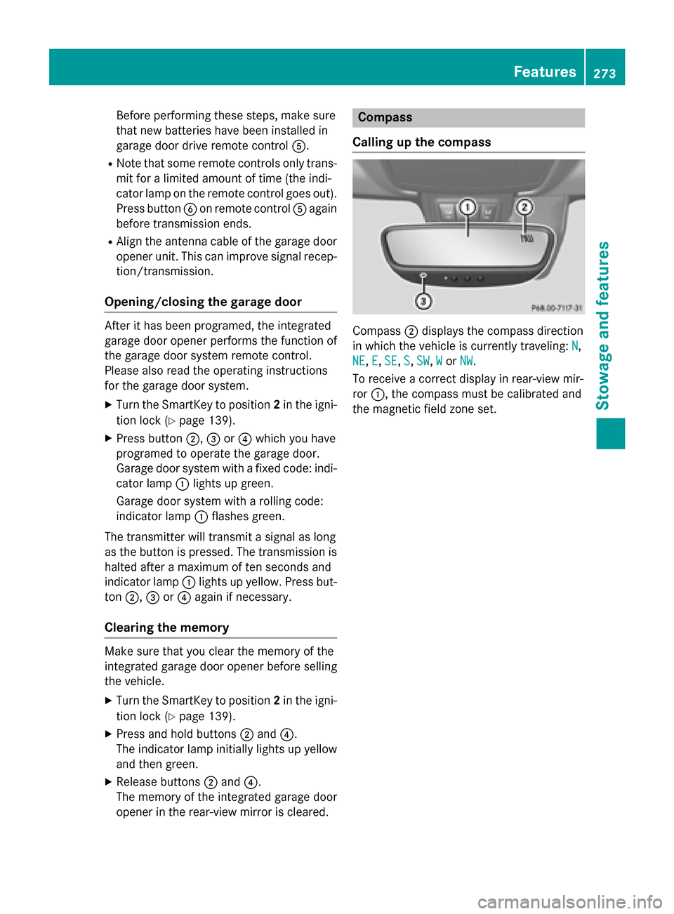
Calling up the compass Compass
0044displays the compass direction
in which the vehicle is currently traveling: N N,
NE
NE, E
E,SE
SE, S
S, SW
SW, W
Wor NW
NW.
To receive a correct display in rear-view mir-
ror 0043, the compass must be calibrated and
the magnetic field zone set. Features
273Stowage and features Z
Page 295 of 358

X
If possible, bring the front wheels into the
straight-ahead position.
X Switch off the engine.
X Vehicles without KEYLESS-GO: remove
the SmartKey from the ignition lock.
X Vehicles with KEYLESS-GO: open the
driver's door.
The on-board electronics now have status
0. This is the same as the SmartKey having
been removed.
X Vehicles with KEYLESS-GO: remove the
Start/Stop button from the ignition lock
(Y page 140).
X All occupants must get out of the vehicle.
Make sure that they are not endangered as they do so.
X Make sure that no one is near the danger
area while a wheel is being changed. Any-
one who is not directly assisting in the
wheel change should, for example, stand
behind the barrier.
X Get out of the vehicle. Pay attention to traf-
fic conditions when doing so.
X Close the driver's door. MOExtended tires (tires with run-flat
properties)
General notes With MOExtended tires (tires with run flat
characteristics), you can continue to drive
your vehicle even if there is a total loss of
pressure in one or more tires. The affected
tire must not show any clearly visible damage.
You can recognize MOExtended tires by the
MOExtended marking which appears on the
sidewall of the tire. You will find this marking next to the tire size designation, the load-
bearing capacity and the speed index
(Y page 326).
MOExtended tires may only be used in con-
junction with an active tire pressure loss
warning system or with an active tire pressure
monitor. If the pressure loss warning message
appears in the multifunction display:
R Observe the instructions in the display
messages (Y page 236).
R Check the tire for damage.
R If driving on, observe the following notes.
The maximum driving distance is approx-
imately 50 miles (80 km) when the vehicle is
partially laden and approximately 18 miles
(30 km) when the vehicle is fully laden.
In addition to the vehicle load, the driving dis- tance possible depends upon:
R Speed
R Road condition
R Outside temperature
The driving distance possible in run-flat mode may be reduced by extreme driving condi-
tions/maneuvers, or it can be increased
through a moderate style of driving.
The maximum permissible distance which
can be driven in run-flat mode is counted fromthe moment the tire pressure loss warning
appears in the multifunction display.
You must not exceed a maximum speed of
50 mph (80 km/h).
i When replacing one or all tires, make sure
that you use only tires:
R of the size specified for the vehicle and
R marked "MOExtended"
If a tire has gone flat and cannot be
replaced with a MOExtended tire, a stand-
ard tire may be used as a temporary meas-
ure. Make sure that you use the proper size and type (summer or winter tire).
i Vehicles equipped with MOExtended tires
are not equipped with a TIREFIT kit at the
factory. It is therefore recommended that
you additionally equip your vehicle with a
TIREFIT kit if you mount tires that do not
feature run-flat properties, e.g. winter tires. A TIREFIT kit is available, for example, from
a qualified specialist workshop. Flat tire
293Breakdown assistance
Page 335 of 358

Cleaning the wheels
G
WARNING
The water jet from a circular jet nozzle (dirt
blasters) can cause invisible exterior damage to the tires or chassis components. Compo-
nents damaged in this way may fail unexpect-edly. There is a risk of an accident.
Do not use power washers with circular jet
nozzles to clean the vehicle. Have damaged
tires or chassis components replaced imme-
diately. Mounting a wheel
Preparing the vehicle X
Stop the vehicle on solid, non-slippery and
level ground.
X Apply the electric parking brake manually.
X Bring the front wheels into the straight-
ahead position.
X Vehicles with manual transmission:
fully depress the clutch pedal and engage
first or reverse gear.
X Vehicles with automatic transmission:
move the selector lever to P.
X Switch off the engine.
X Vehicles without KEYLESS-GO: remove
the SmartKey from the ignition lock.
X Vehicles with KEYLESS-GO: open the
driver's door.
The on-board electronics now have status
0. This is the same as the SmartKey having
been removed.
X Vehicles with KEYLESS-GO: remove the
Start/Stop button from the ignition lock
(Y page 140).
X If included in the vehicle equipment,
remove the tire-change tool kit from the
vehicle.
X Secure the vehicle to prevent it from rolling
away. i
Due to differences in vehicle equipment,
not all vehicles are equipped with a tire-
change tool kit. For information on which
tools are required to perform a wheel
change on your vehicle, consult an author- ized Mercedes-Benz Center.
Necessary wheel-changing tools can
include, for example:
R Jack
R Wheel chock
R Lug wrench
Securing the vehicle to prevent it from
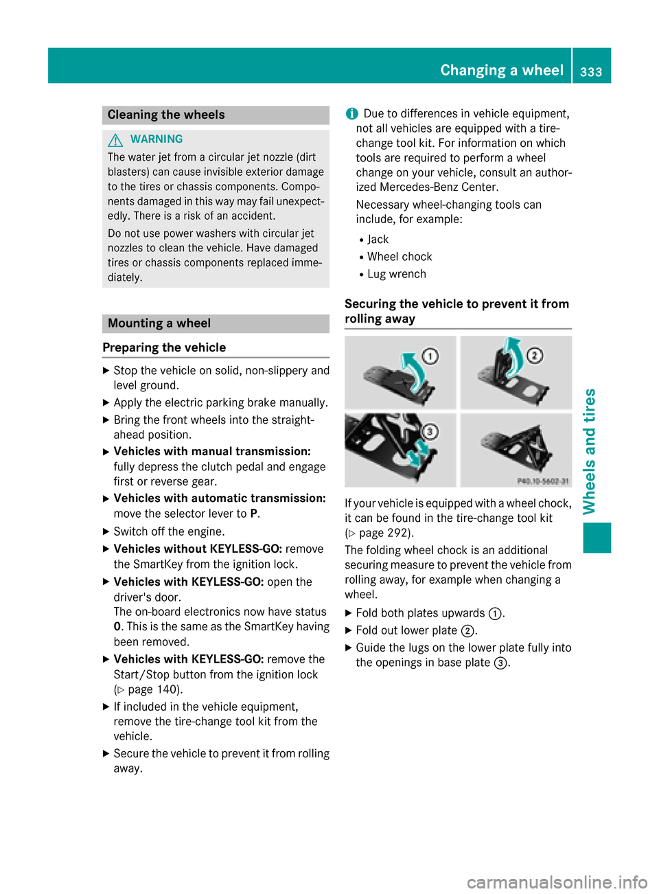
rolling away If your vehicle is equipped with a wheel chock,
it can be found in the tire-change tool kit
(Y page 292).
The folding wheel chock is an additional
securing measure to prevent the vehicle from
rolling away, for example when changing a
wheel.
X Fold both plates upwards 0043.
X Fold out lower plate 0044.
X Guide the lugs on the lower plate fully into
the openings in base plate 0087. Changing a wheel
333Wheels and tires Z
Page 336 of 358

Securing the vehicle on level ground
X On level ground: place chocks or other
suitable items under the front and rear of
the wheel that is diagonally opposite the
wheel you wish to change. Securing the vehicle on slight downhill gradients
X On light downhill gradients: place
chocks or other suitable items in front of
the wheels of the front and rear axle.
Raising the vehicle G
WARNING
If you do not position the jack correctly at the appropriate jacking point of the vehicle, the
jack could tip over with the vehicle raised.
There is a risk of injury.
Only position the jack at the appropriate jack-
ing point of the vehicle. The base of the jack
must be positioned vertically, directly under
the jacking point of the vehicle.
! The jack is designed exclusively for jack-
ing up the vehicle at the jacking points.
Otherwise, your vehicle could be damaged. The following must be observed when raising
the vehicle:
R to raise the vehicle, only use the vehicle-
specific jack that has been tested and
approved by Mercedes-Benz. If used incor-
rectly, the jack could tip over with the vehi-
cle raised.
R the jack is designed only to raise and hold
the vehicle for a short time while a wheel
is being changed. It is not suited for per-
forming maintenance work under the vehi- cle.
R avoid changing the wheel on uphill and
downhill slopes.
R before raising the vehicle, secure it from
rolling away by applying the parking brake
and inserting wheel chocks. Never disen-
gage the parking brake while the vehicle is raised.
R the jack must be placed on a firm, flat and
non-slip surface. On a loose surface, a
large, flat, load-bearing underlay must be
used. On a slippery surface, a non-slip
underlay must be used, e.g. rubber mats.
R do not use wooden blocks or similar
objects as a jack underlay. Otherwise, the
jack will not be able to achieve its load-
bearing capacity due to the restricted
height.
R make sure that the distance between the
underside of the tires and the ground does
not exceed 1.2 in (3 cm).
R never place your hands and feet under the
raised vehicle.
R do not lie under the vehicle.
R do not start the engine when the vehicle is
raised.
R do not open or close a door or the trunk lid
when the vehicle is raised.
R make sure that no persons are present in
the vehicle when the vehicle is raised. 334
Changing a wheelWheels and tires