2015 MERCEDES-BENZ SLK-Class remove seats
[x] Cancel search: remove seatsPage 23 of 358

Protection of the environment
General notes
H
Environmental note
Daimler's declared policy is one of compre-
hensive environmental protection.
The objectives are for the natural resources
that form the basis of our existence on this
planet to be used sparingly and in a manner
that takes the requirements of both nature
and humanity into account.
You too can help to protect the environment
by operating your vehicle in an environmen-
tally responsible manner.
Fuel consumption and the rate of engine,
transmission, brake and tire wear are affected by these factors:
R operating conditions of your vehicle
R your personal driving style
You can influence both factors. You should
bear the following in mind:
Operating conditions:
R avoid short trips as these increase fuel con-
sumption.
R always make sure that the tire pressures
are correct.
R do not carry any unnecessary weight.
R remove roof racks once you no longer need
them.
R a regularly serviced vehicle will contribute
to environmental protection. You should
therefore adhere to the service intervals.
R always have service work carried out at a
qualified specialist workshop.
Personal driving style:
R do not depress the accelerator pedal when
starting the engine.
R do not warm up the engine when the vehicle
is stationary.
R drive carefully and maintain a safe distance
from the vehicle in front.
R avoid frequent, sudden acceleration and
braking. R
change gear in good time and use each gear
only up to 00C3of its maximum engine speed.
R switch off the engine in stationary traffic.
R keep an eye on the vehicle's fuel consump-
tion. Environmental concerns and recom-
mendations
Wherever the operating instructions require
you to dispose of materials, first try to regen-
erate or re-use them. Observe the relevant
environmental rules and regulations when
disposing of materials. In this way you will
help to protect the environment. Genuine Mercedes-Benz parts
H
Environmental note
Daimler AG also supplies reconditioned major
assemblies and parts which are of the same
quality as new parts. They are covered by the same Limited Warranty entitlements as new
parts.
! Air bags and Emergency Tensioning Devi-
ces, as well as control units and sensors for these restraint systems, may be installed inthe following areas of your vehicle:
R doors
R door pillars
R door sills
R seats
R cockpit
R instrument cluster
R center console
Do not install accessories such as audio
systems in these areas. Do not carry out
repairs or welding. You could impair the
operating efficiency of the restraint sys-
tems.
Have aftermarket accessories installed at a qualified specialist workshop. Introduction
21 Z
Page 100 of 358

moving the seats back. There is a risk that
the seats and/or the objects could be dam-
aged.
i The head restraints are installed with the
NECK-PRO system (Y page 56). For this
reason, it is not possible to remove the
head restraints from the seats.
For more information, contact a qualified
specialist workshop. Adjusting the seats manually
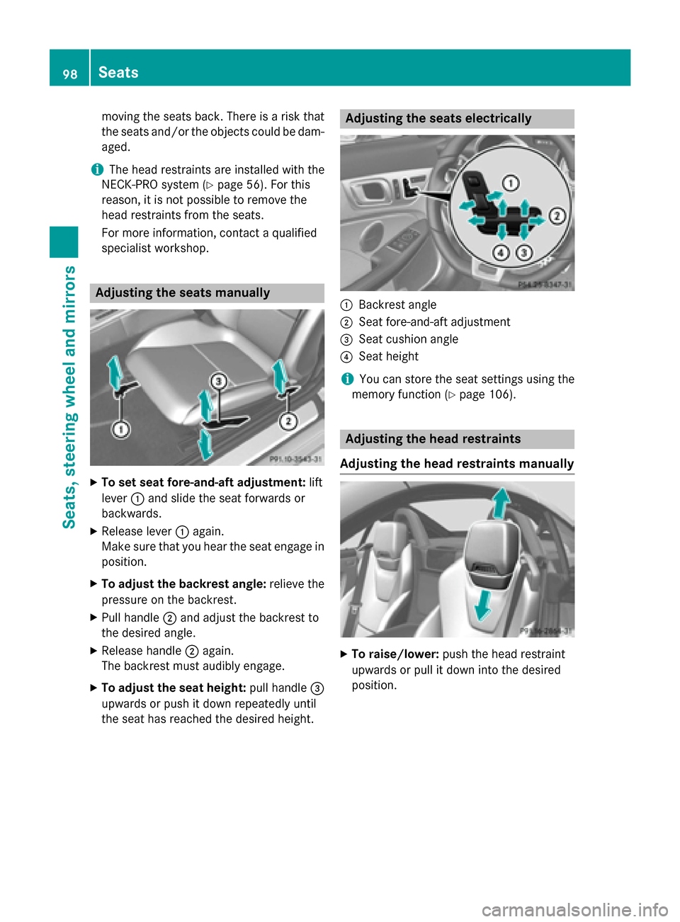
X
To set seat fore-and-aft adjustment: lift
lever 0043and slide the seat forwards or
backwards.
X Release lever 0043again.
Make sure that you hear the seat engage in
position.
X To adjust the backrest angle: relieve the
pressure on the backrest.
X Pull handle 0044and adjust the backrest to
the desired angle.
X Release handle 0044again.
The backrest must audibly engage.
X To adjust the seat height: pull handle0087
upwards or push it down repeatedly until
the seat has reached the desired height. Adjusting the seats electrically
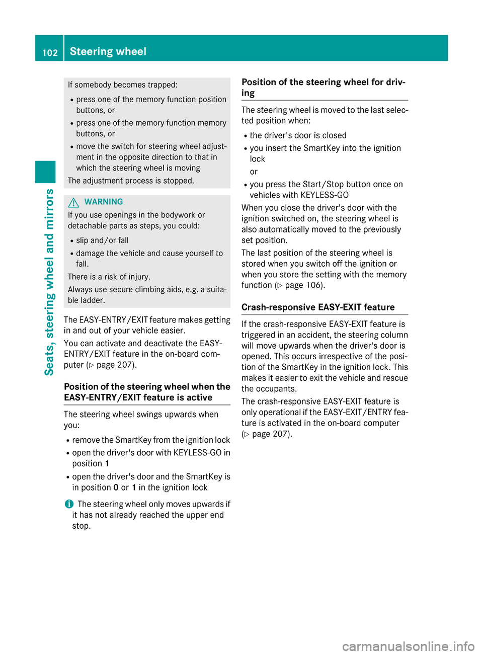
0043
Backrest angle
0044 Seat fore-and-aft adjustment
0087 Seat cushion angle
0085 Seat height
i You can store the seat settings using the
memory function (Y page 106). Adjusting the head restraints
Adjusting the head restraints manually X
To raise/lower: push the head restraint
upwards or pull it down into the desired
position. 98
SeatsSeats, steering wheel and mirrors
Page 104 of 358

If somebody becomes trapped:
R press one of the memory function position
buttons, or
R press one of the memory function memory
buttons, or
R move the switch for steering wheel adjust-
ment in the opposite direction to that in
which the steering wheel is moving
The adjustment process is stopped. G
WARNING
If you use openings in the bodywork or
detachable parts as steps, you could:
R slip and/or fall
R damage the vehicle and cause yourself to
fall.
There is a risk of injury.
Always use secure climbing aids, e.g. a suita-
ble ladder.
The EASY-ENTRY/EXIT feature makes getting
in and out of your vehicle easier.
You can activate and deactivate the EASY-
ENTRY/EXIT feature in the on-board com-
puter (Y page 207).
Position of the steering wheel when the EASY-ENTRY/EXIT feature is active The steering wheel swings upwards when
you:
R remove the SmartKey from the ignition lock
R open the driver's door with KEYLESS-GO in
position 1
R open the driver's door and the SmartKey is
in position 0or 1in the ignition lock
i The steering wheel only moves upwards if
it has not already reached the upper end
stop. Position of the steering wheel for driv-
ing The steering wheel is moved to the last selec-
ted position when:
R the driver's door is closed
R you insert the SmartKey into the ignition
lock
or
R you press the Start/Stop button once on
vehicles with KEYLESS-GO
When you close the driver's door with the
ignition switched on, the steering wheel is
also automatically moved to the previously
set position.
The last position of the steering wheel is
stored when you switch off the ignition or
when you store the setting with the memory
function (Y page 106).
Crash-responsive EASY-EXIT feature If the crash-responsive EASY-EXIT feature is
triggered in an accident, the steering column
will move upwards when the driver's door is
opened. This occurs irrespective of the posi-
tion of the SmartKey in the ignition lock. This
makes it easier to exit the vehicle and rescue the occupants.
The crash-responsive EASY-EXIT feature is
only operational if the EASY-EXIT/ENTRY fea-
ture is activated in the on-board computer
(Y page 207). 102
Steering wheelSeats, steering wheel and mirrors
Page 259 of 358

Stowage compartment/telephone
compartment under the armrest
X
To open: push button 0043up and raise arm-
rest 0044.
The stowage compartment can be locked and
unlocked centrally using the SmartKey
(Y page 72).
i Depending on the vehicle equipment, a
12 V power socket, USB port or a Media
Interface is installed in the stowage com-
partment. A Media Interface is a universal
interface for mobile audio equipment, e.g.
for an iPod ®
or MP3 player (see the sepa-
rate COMAND Operating Instructions).
Eyeglasses compartment X
To open: press marking 0043.
Make sure that the eyeglasses compartment
is always closed while the vehicle is in motion. Stowage compartment in the center
console
X
To open: briefly press the lower section of
cover 0043.
X To remove the insert: pull the left-hand
side of the insert up and out.
X To install the insert: press the insert into
the housing.
Depending on the vehicle equipment, there
may be an ashtray in the center console
instead of a storage compartment.
Stowage compartment in the doors In the door trim, there is a ruffled pocket
0044
with storage slot 0043.
Stowage box in the rear wall between
the seats A ruffled pocket is located on the rear wall
between the seats. Stowage areas
257Stowage and features Z
Page 299 of 358

X
To reduce the tire pressure: depress
pressure release button 0043next to pres-
sure gauge 0044.
X When the tire pressure is correct, unscrew
the filler hose from the valve of the sealed
tire.
X Screw the valve cap onto the tire valve of
the sealed tire. X
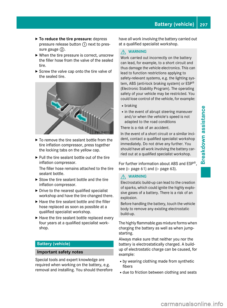
To remove the tire sealant bottle from the
tire inflation compressor, press together
the locking tabs on the yellow cap.
X Pull the tire sealant bottle out of the tire
inflation compressor.
The filler hose remains attached to the tire
sealant bottle.
X Stow the tire sealant bottle and the tire
inflation compressor.
X Drive to the nearest qualified specialist
workshop and have the tire changed there.
X Have the tire sealant bottle and the filler
hose replaced as soon as possible at a
qualified specialist workshop.
X Have the tire sealant bottle replaced every
four years at a qualified specialist work-
shop. Battery (vehicle)
Important safety notes
Special tools and expert knowledge are
required when working on the battery, e.g.
removal and installing. You should therefore have all work involving the battery carried out
at a qualified specialist workshop. G
WARNING
Work carried out incorrectly on the battery
can lead, for example, to a short circuit and
thus damage the vehicle electronics. This can lead to function restrictions applying to
safety-relevant systems, e.g. the lighting sys-
tem, ABS (anti-lock braking system) or ESP ®
(Electronic Stability Program). The operating
safety of your vehicle may be restricted. You
could lose control of the vehicle, for example:
R braking
R in the event of abrupt steering maneuver
and/or when the vehicle's speed is not
adapted to the road conditions
There is a risk of an accident.
In the event of a short circuit or a similar inci- dent, contact a qualified specialist workshop
immediately. Do not drive any further. You
should have all work involving the battery car-
ried out at a qualified specialist workshop.
For further information about ABS and ESP ®
,
see (Y page 61) and (Y page 63). G
WARNING
Electrostatic build-up can lead to the creation of sparks, which could ignite the highly explo-
sive gases of a battery. There is a risk of an
explosion.
Before handling the battery, touch the vehicle body to remove any existing electrostatic
build-up.
The highly flammable gas mixture forms when
charging the battery as well as when jump-
starting.
Always make sure that neither you nor the
battery is electrostatically charged. A build-
up of electrostatic charge can be caused, for
example:
R by wearing clothing made from synthetic
fibers
R due to friction between clothing and seats Battery (vehicle)
297Breakdown assis tance Z