2015 MERCEDES-BENZ SLK-Class spare wheel
[x] Cancel search: spare wheelPage 328 of 358
Tire labeling
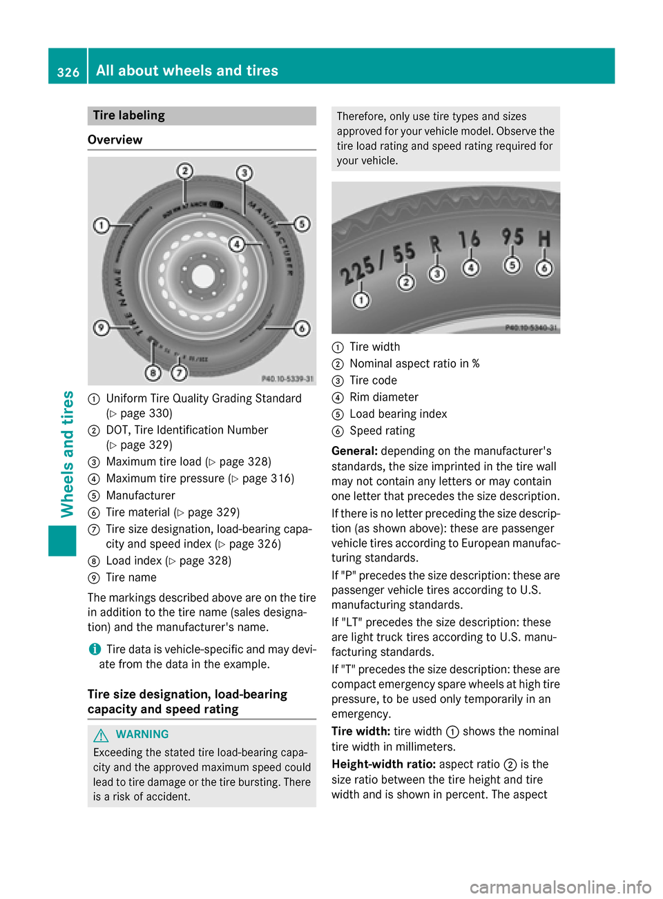
Overview 0043
Uniform Tire Quality Grading Standard
(Ypage 330)
0044 DOT, Tire Identification Number
(Ypage 329)
0087 Maximum tire load (Y page 328)
0085 Maximum tire pressure (Y page 316)
0083 Manufacturer
0084 Tire material (Y page 329)
006B Tire size designation, load-bearing capa-
city and speed index (Y page 326)
006C Load index (Y page 328)
006D Tire name
The markings described above are on the tire in addition to the tire name (sales designa-
tion) and the manufacturer's name.
i Tire data is vehicle-specific and may devi-
ate from the data in the example.
Tire size designation, load-bearing
capacity and speed rating G
WARNING
Exceeding the stated tire load-bearing capa-
city and the approved maximum speed could
lead to tire damage or the tire bursting. There is a risk of accident. Therefore, only use tire types and sizes
approved for your vehicle model. Observe the
tire load rating and speed rating required for
your vehicle. 0043
Tire width
0044 Nominal aspect ratio in %
0087 Tire code
0085 Rim diameter
0083 Load bearing index
0084 Speed rating
General: depending on the manufacturer's
standards, the size imprinted in the tire wall
may not contain any letters or may contain
one letter that precedes the size description.
If there is no letter preceding the size descrip-
tion (as shown above): these are passenger
vehicle tires according to European manufac-
turing standards.
If "P" precedes the size description: these are
passenger vehicle tires according to U.S.
manufacturing standards.
If "LT" precedes the size description: these
are light truck tires according to U.S. manu-
facturing standards.
If "T" precedes the size description: these are compact emergency spare wheels at high tire
pressure, to be used only temporarily in an
emergency.
Tire width: tire width0043shows the nominal
tire width in millimeters.
Height-width ratio: aspect ratio0044is the
size ratio between the tire height and tire
width and is shown in percent. The aspect 326
All about
wheels and tiresWheels and tires
Page 332 of 358
Bar
Metric unit for tire pressure. 14.5038 pounds
per square inch (psi) and 100 kilopascals
(kPa) are the equivalent of 1 bar.
DOT (Department of Transportation)
DOT marked tires fulfill the requirements of
the United States Department of Transporta- tion.
Normal occupant weight
The number of occupants which the vehicle is
designed for, multiplied by 68 kilograms
(150 lb).
Uniform Tire Quality Grading Standards
A uniform standard to grade the quality of
tires with regards to tread quality, tire traction and temperature characteristics. Ratings are
determined by tire manufacturers using U.S.
government testing procedures. The ratings
are molded into the sidewall of the tire.
Recommended tire pressure
The recommended tire pressure applies to
the tires mounted at the factory.
The Tire and Loading Information placard con- tains the recommended tire pressures for
cold tires on a fully loaded vehicle and for themaximum permissible vehicle speed.
The tire pressure table contains the recom-
mended pressures for cold tires for various
operating conditions, i.e. differing load and
speed conditions.
Increased vehicle weight due to optional
equipment
This is the combined weight of all standard
and optional equipment available for the vehi-
cle, regardless of whether it is actually instal-
led on the vehicle or not.
Rim
This is the part of the wheel on which the tire
is mounted. GAWR (Gross Axle Weight Rating)
The GAWR is the maximum permissible axle
weight. The actual load on an axle must never exceed the gross axle weight rating. The
gross axle weight rating can be found on the
vehicle identification plate on the B-pillar on
the driver's side.
Speed rating
The speed rating is part of the tire identifica-
tion. It specifies the speed range for which the
tire is approved.
GVW (Gross Vehicle Weight)
The gross vehicle weight includes the weight
of the vehicle including fuel, tools, the spare
wheel, accessories installed, occupants, lug-
gage and the drawbar noseweight, if applica-
ble. The gross vehicle weight must not exceed the gross vehicle weight rating GVWR as
specified on the vehicle identification plate on
the B pillar on the driver's side.
GVWR (Gross Vehicle Weight Rating)
The GVWR is the maximum permissible gross weight of a fully loaded vehicle (the weight of the vehicle including all accessories, occu-
pants, fuel, luggage and the drawbar nose-
weight, if applicable). The gross vehicle
weight rating is specified on the vehicle iden-
tification plate on the B-pillar on the driver's
side.
Maximum loaded vehicle weight
The maximum weight is the sum of:
R the curb weight of the vehicle
R the weight of the accessories
R the load limit
R the weight of the factory installed optional
equipment
Kilopascal (kPa)
Metric unit for tire pressure. 6.9 kPa corre-
sponds to 1 psi. Another unit for tire pressure is bar. There are 100 kilopascals (kPa) to
1 bar. 330
All about wheels and tiresWheels and tires
Page 338 of 358
X
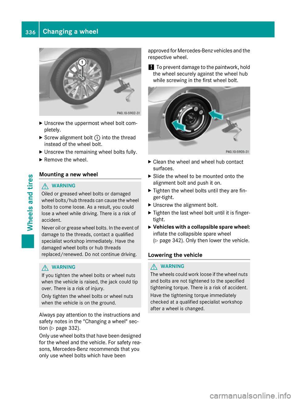
Unscrew the uppermost wheel bolt com-
pletely.
X Screw alignment bolt 0043into the thread
instead of the wheel bolt.
X Unscrew the remaining wheel bolts fully.
X Remove the wheel.
Mounting a new wheel G
WARNING
Oiled or greased wheel bolts or damaged
wheel bolts/hub threads can cause the wheel bolts to come loose. As a result, you could
lose a wheel while driving. There is a risk of
accident.
Never oil or grease wheel bolts. In the event ofdamage to the threads, contact a qualified
specialist workshop immediately. Have the
damaged wheel bolts or hub threads
replaced/renewed. Do not continue driving. G
WARNING
If you tighten the wheel bolts or wheel nuts
when the vehicle is raised, the jack could tip
over. There is a risk of injury.
Only tighten the wheel bolts or wheel nuts
when the vehicle is on the ground.
Always pay attention to the instructions and
safety notes in the "Changing a wheel" sec-
tion (Y page 332).
Only use wheel bolts that have been designed for the wheel and the vehicle. For safety rea-
sons, Mercedes-Benz recommends that you
only use wheel bolts which have been approved for Mercedes-Benz vehicles and the
respective wheel.
! To prevent damage to the paintwork, hold
the wheel securely against the wheel hub
while screwing in the first wheel bolt. X
Clean the wheel and wheel hub contact
surfaces.
X Slide the wheel to be mounted onto the
alignment bolt and push it on.
X Tighten the wheel bolts until they are fin-
ger-tight.
X Unscrew the alignment bolt.
X Tighten the last wheel bolt until it is finger-
tight.
X Vehicles with a collapsible spare wheel:
inflate the collapsible spare wheel
(Y page 342). Only then lower the vehicle.
Lowering the vehicle G
WARNING
The wheels could work loose if the wheel nuts and bolts are not tightened to the specified
tightening torque. There is a risk of accident.
Have the tightening torque immediately
checked at a qualified specialist workshop
after a wheel is changed. 336
Changing a wheelWheels and tires
Page 339 of 358

X
Turn the crank of the jack counter-clock-
wise until the vehicle is once again standing
firmly on the ground.
X Place the jack to one side.
X Tighten the wheel bolts evenly in a cross-
wise pattern in the sequence indicated ( 0043
to 0083). The specified tightening torque is
96 lb-ft (130 Nm).
X Turn the jack back to its initial position.
X Stow the jack and the rest of the vehicle
tools in the trunk again.
X AMG vehicles and vehicles with AMG
equipment: insert the cover into the outer
sill.
X Check the tire pressure of the newly moun-
ted wheel and adjust it if necessary.
Observe the recommended tire pressure
(Y page 314).
i When you are driving with the collapsible
spare wheel mounted, the tire pressure
loss warning system or the tire pressure
monitor cannot function reliably. Only
restart the tire pressure loss warning sys-
tem/the tire pressure monitor when the
damaged wheel has been replaced with a
new wheel.
Vehicles with a tire pressure control
system: all installed wheels must be equip-
ped with functioning sensors. Wheel and tire combinations
General notes
! For safety reasons, Mercedes-Benz rec-
ommends that you only use tires and
wheels which have been approved by
Mercedes-Benz specifically for your vehi-
cle.
These tires have been specially adapted for use with the control systems, such as ABS
or ESP ®
, and are marked as follows:
R MO = Mercedes-Benz Original
R MOE = Mercedes-Benz Original Extended
(tires featuring run-flat characteristics)
R MO1 = Mercedes-Benz Original (only cer-
tain AMG tires)
Mercedes-Benz Original Extended tires
may only be used on wheels that have been
specifically approved by Mercedes-Benz.
Only use tires, wheels or accessories tes-
ted and approved by Mercedes-Benz. Cer-
tain characteristics, e.g. handling, vehicle
noise emissions or fuel consumption, may
otherwise be adversely affected. In addi-
tion, when driving with a load, tire dimen-
sion variations could cause the tires to
come into contact with the bodywork and
axle components. This could result in dam- age to the tires or the vehicle.
Mercedes-Benz accepts no liability for
damage resulting from the use of tires,
wheels or accessories other than those tes-
ted and approved.
Information on tires, wheels and approved
combinations can be obtained from any
qualified specialist workshop.
! Retreaded tires are neither tested nor rec-
ommended by Mercedes-Benz, since pre-
vious damage cannot always be detected
on retreaded tires. As a result, Mercedes-
Benz cannot guarantee vehicle safety if
retreaded tires are mounted. Do not mount used tires if you have no information about
their previous usage. Wheel and tire combinations
337Wheels and tires Z
Page 343 of 358

Emergency spare wheel
Important safety notes
G
WARNING
The wheel or tire size as well as the tire type of the spare wheel or emergency spare wheel
and the wheel to be replaced may differ.
Mounting an emergency spare wheel may
severely impair the driving characteristics.
There is a risk of an accident.
To avoid hazardous situations:
R adapt your driving style accordingly and
drive carefully.
R never mount more than one spare wheel or
emergency spare wheel that differs in size.
R only use a spare wheel or emergency spare
wheel of a different size briefly.
R do not switch ESP ®
off.
R have a spare wheel or emergency spare
wheel of a different size replaced at the
nearest qualified specialist workshop.
Observe that the wheel and tire dimensions
as well as the tire type must be correct.
When using an emergency spare wheel or
spare wheel of a different size, you must not
exceed the maximum speed of 50 mph
(80 km/h).
Snow chains must not be mounted on emer-
gency spare wheels. General notes
You should regularly check the pressure of
the emergency spare wheel, particularly prior
to long trips, and correct the pressure as nec-
essary (Y page 314). The applicable value is
found on the wheel or under "Technical data"
(Y page 344).
An emergency spare wheel may also be
mounted against the direction of rotation.
Observe the time restriction on use as well as
the speed limitation specified on the emer-
gency spare wheel. Replace the tires after six years at the latest,
regardless of wear. This also applies to the
emergency spare wheel.
i When you are driving with the collapsible
spare wheel mounted, the tire pressure
loss warning system or the tire pressure
monitor cannot function reliably. Only
restart the tire pressure loss warning sys-
tem/the tire pressure monitor when the
damaged wheel has been replaced with a
new wheel.
Vehicles with tire pressure monitor:
after mounting an emergency spare wheel,
the system may still display the tire pres-
sure of the removed wheel for a few
minutes. The value displayed for the moun- ted emergency spare wheel is not the sameas the current tire pressure of the emer-
gency spare wheel. Removing the emergency spare wheel
(Example)
The collapsible spare wheel can be found in
the stowage well under the trunk floor. X Lift and remove the reversible floor panel in
the trunk (Y page 258).
X Turn retaining screw 0044counter-clockwise
and remove it.
X Remove collapsible spare wheel 0043.
Always observe the instructions and safety
notes in the "Mounting a wheel" section
(Y page 333). Emergency spare wheel
341Wheels and tires Z
Page 344 of 358
Stowing the emergency spare wheel
! Only place the collapsible spare wheel in
the vehicle when it is dry. Otherwise, mois-
ture may get into the vehicle.
Take the following steps to stow a used col-
lapsible spare wheel. Otherwise, the collaps-
ible spare wheel will not fit in the trunk in the
intended manner. Mercedes-Benz recom-
mends that you have this work carried out at
a qualified specialist workshop.
X Unscrew the valve cap from the valve.
X If possible, unscrew the valve insert from
the valve and release the air.
i Fully deflating the tires can take a few
minutes.
X Screw the valve insert back into the valve.
X Screw the valve cap back on.
X Pull the protective sheet provided with the
spare wheel over the collapsible spare
wheel.
X Stow the collapsible spare wheel in the
emergency spare wheel well under the
trunk.
X Use the retaining screw to pierce the pro-
tective sheet and fasten the collapsible
spare wheel in place. Inflating the collapsible spare wheel
! Inflate the collapsible spare wheel using
the tire inflation compressor before lower-
ing the vehicle. The wheel rim could other-
wise be damaged.
! Do not operate the tire inflation compres-
sor for longer than ten minutes at a time
without a break. It may otherwise overheat.
The tire inflation compressor can be oper-
ated again once it has cooled down. X
Mount the collapsible spare wheel as
described (Y page 333).
The collapsible spare wheel must be moun-
ted before it is inflated.
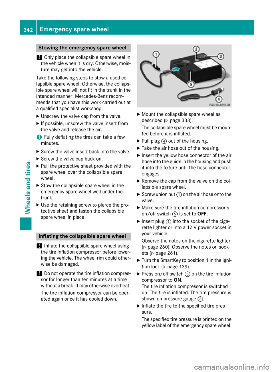
X Pull plug 0085out of the housing.
X Take the air hose out of the housing.
X Insert the yellow hose connector of the air
hose into the guide in the housing and push it into the fixture until the hose connector
engages.
X Remove the cap from the valve on the col-
lapsible spare wheel.
X Screw union nut 0043on the air hose onto the
valve.
X Make sure the tire inflation compressor's
on/off switch 0083is set to OFF.
X Insert plug 0085into the socket of the ciga-
rette lighter or into a 12 V power socket in your vehicle.
Observe the notes on the cigarette lighter
(Y page 260). Observe the notes on sock-
ets (Y page 261).
X Turn the SmartKey to position 1in the igni-
tion lock (Y page 139).
X Press on/off switch 0083on the tire inflation
compressor to ON.
The tire inflation compressor is switched
on. The tire is inflated. The tire pressure is
shown on pressure gauge 0087.
X Inflate the tire to the specified tire pres-
sure.
The specified tire pressure is printed on the
yellow label of the emergency spare wheel. 342
Emergency spare wheelWheels and tires
Page 345 of 358
X
When the specified tire pressure has been
reached, press on/off switch 0083toOFF, on
the tire inflation compressor.
The tire inflation compressor is switched
off.
X Turn the SmartKey to position 0in the igni-
tion lock.
X If the tire pressure is higher than the speci-
fied pressure, press pressure release but-
ton 0044until the correct tire pressure has
been reached.
X Unscrew union nut 0043on the air hose from
the valve.
X Screw the cap onto the valve of the col-
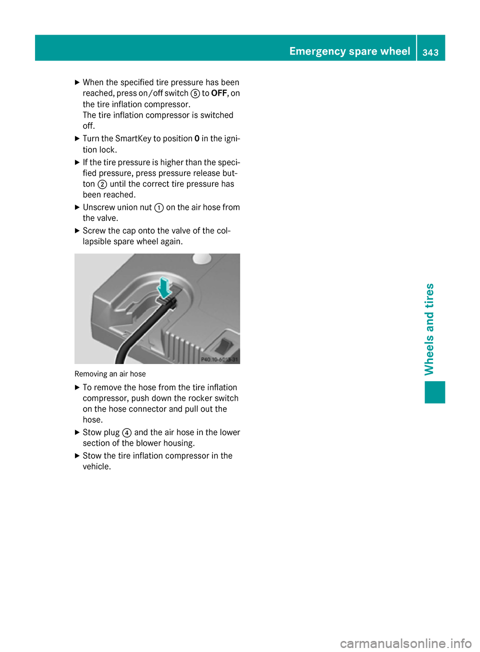
lapsible spare wheel again. Removing an air hose
X
To remove the hose from the tire inflation
compressor, push down the rocker switch
on the hose connector and pull out the
hose.
X Stow plug 0085and the air hose in the lower
section of the blower housing.
X Stow the tire inflation compressor in the
vehicle. Emergency spare wheel
343Wheels and tires Z
Page 346 of 358

Technical data
All models Collapsible spare wheel
6Tires Alloy wheels
145/70-17 92 P
Tire pressure: 350 kPa (3.5 bar/51 psi) 4.5 B x 17 H2
Wheel offset: 0.47 in (12 mm)
Depending on the country, the engine and the wheels mounted, your vehicle may be equipped
with TIREFIT or a collapsible spare wheel.
i The specified tire pressure is printed in yellow on the emergency spare wheel.
6 Use of snow chains is not permitted. Observe the notes in the section on snow chains. 344
Emergency spare
wheelWheels and tires