2015 MERCEDES-BENZ GLE SUV towing
[x] Cancel search: towingPage 25 of 453
With both axles on the ground .......4
01
Towing eye ......................................... 387
Traffic Sign Assist
Activating/deactivating the warn-ing function ................................... .290
Display message ............................ 325
Function/notes ............................ .242
Important safety notes .................. 242
Instrument cluster display ............. 243
Trailer coupling
see Towing a trailer
Trailer towing
7-pin connector ............................ .278
Blind Spot Assist ............................ 246
Cleaning the trailer tow hitch ......... 383
Coupling up a trailer ..................... .275
Decoupling a trailer ....................... 276
Driving tips ................................... .273
Important safety notes .................. 272
Lights display message .................. 313
Mounting dimensions .................... 446
Parktronic ...................................... 225
Power supply ................................. 277
Problem (fault) ............................... 279
Trailer loads ................................... 447
Transmission
see Automatic transmission
Transmission position display ......... 168
Transmission position display
(DIRECT SELECT lever) ......................168
Transporting the vehicle .................. 401
Travelling uphill
Brow of hill ..................................... 202
Driving downhill ............................ .202
Maximum gradient-climbing capa-
bility ............................................... 202
Trim pieces (cleaning instruc-
tions) ................................................. .384
Trip computer (on-board com-
puter) ................................................. .284
Trip meter
Calling up ....................................... 284
Resetting (on-board computer) ...... 285
Turn signals
Changing bulbs (front) ................... 130
Switching on/off ........................... 123 TV
Operating (on-board computer) ..... 288
see Separate operating instructions
Two-way radio
Frequencies ................................... 433
Installation ..................................... 433
Transmission output (maximum ).... 433
Type identification plate
see Vehicle identification plate
Tyre inflation compressor
see TIREFIT kit
Tyre pressure
Calling up (on-board computer) ..... 411
Display message ............................ 330
Not reached (TIREFIT) .................... 391
Reached (TIREFIT) .......................... 391
Recommended ............................... 408
Tyre pressure loss warning
General notes ................................ 410
Important safety notes .................. 410
Restarting ...................................... 410
Tyre pressure monitor
Checking the tyre pressure elec-
tronically ........................................ 411
Function/note s............................. 411
General notes ................................ 411
Important safety notes .................. 411
Radio type approval for the tyre
pressure monitor ........................... 413
Restarting ...................................... 412
Warning lamp ................................. 350
Warning message .......................... 412
Tyres
Changing a whee l.......................... 413
Checking ........................................ 406
Direction of rotation ...................... 414
Display message ............................ 330
General notes ................................ 418
Important safety notes .................. 405
Information on driving .................... 405
M+S tyres ...................................... 407
MOExtended tyre s......................... 407
Replacing ....................................... 413
Service life ..................................... 406
Storing ........................................... 414
Tyre size (data ).............................. 418
Tyre tread ...................................... 406
Wheel and tyre combinations ........ 419 22
Index
Page 26 of 453
see Flat tyre
U
Unlocking Emergency unlocking ....................... 92
From inside the vehicle (central
unlocking button) ............................. 91
Upshift indicator (on-board com-
puter, Mercedes-AMG vehicles) .......297 V
Vanity mirror (in sun visor) .............. 362
Variable SPEEDTRONIC
see SPEEDTRONIC
Vehicle
Correct use ...................................... 28
Data acquisition ............................... 28
Display message ............................ 332
Electronics ..................................... 433
Equipment ....................................... 26
Implied warranty .............................. 28
Individual settings .......................... 292
Leaving parked up ......................... 194
Locking (in an emergency) .............. .93
Locking (key) ................................... 85
Lowering ........................................ 417
Pulling away ................................... 161
Raising ........................................... 415
Registration ..................................... 28
Securing from rolling away ............ 414
Towing away .................................. 399
Transporting .................................. 401
Unlocking (in an emergency) ........... 92
Unlocking (key) ................................ 85
Vehicle data ................................... 442
Vehicle battery
see Battery (vehicle)
Vehicle data ....................................... 442
Vehicle data (off-road driving)
Approach/departure angle ............ 445
Fording depth ................................ 444
Maximum gradient climbing abil-
ity .................................................. 445
Vehicle dimensions ........................... 442
Vehicle emergency locking ................ 93Vehicle identification number
see VIN
Vehicle identification plate .............. 434
Vehicle level
AIRMATIC ...................................... 222
Vehicle level (display message) ....... 322
Vehicle tool kit .................................. 387
Video
Operating the DVD ......................... 288
VIN ...................................................... 434
Seat ............................................... 435
Type plate ...................................... 434 W
Warning and indicator lamps ABS ................................................ 341
Brakes ........................................... 339
Distance warning signal ................. 349
ESP ®
.............................................. 343
ESP ®
OFF ....................................... 344
Fuel tank ........................................ 347
Hybrid drive system ....................... 340
LIM (cruise control )........................ 203
LIM (DISTRONIC PLUS) .................. 208
LIM (variable SPEEDTRONIC) ......... 205
Overview .......................................... 34
Parking brake ................................ 346
PASSENGER AIR BAG ...................... 44
RBS (Recuperative Brake Sys-
tem) ............................................... 340
Reserve fuel ................................... 347
Seat belt ........................................ 337
Tyre pressure monitor ................... 350
Warning triangle ................................ 386
Warnings
Stickers ........................................... 41
Washer fluid
Display message ............................ 336
Wheel and tyre combinations
Tyres .............................................. 419
Wheel bolt tightening torque ........... 417
Wheel chock ...................................... 414
Wheels
Changing a whee l.......................... 413
Changing/replacing ....................... 413
Checking ........................................ 406
Cleaning ......................................... 381 Index
23
Page 44 of 453
Useful information
i This Owner's Manual describes all models,
series and optional equipment for your vehi-
cle that were available at the time of going to
press. National variations are possible. Note
that your vehicle may not be equipped with all
of the functions described. This is also the
case for systems and functions relevant to
safety.
i Read the information on qualified specialist
workshops: (Y page 28). Hybrid vehicles
General notes
Hybrid technology combines a fuel-efficient
internal combustion engine with a powerful
electric motor. Important safety notes
Danger of electric shock G
DANGER
The vehicle's high voltage electrical system is under high voltage. If you modify components
in the vehicle's high-voltage electrical system or touch damaged components, you may be
electrocuted. The components in the vehi-
cle's high-voltage electrical system may be
damaged in an accident, although the damage
is not visible. There is a risk of fatal injury.
Do not touch any high-voltage components
after an accident and never modify the vehi-
cle's high-voltage electrical system. Have the vehicle towed away after an accident and the vehicle's high-voltage electrical system
checked by a qualified specialist workshop.
When towing a vehicle after an accident, be sure
to observe the following sections:
R Transporting the vehicle (Y page 401)
R Towing the vehicle with both axles on the
ground (Y page 401)
Read the safety instructions on towing and tow- starting (Y page 399). All components of the hybrid drive system are
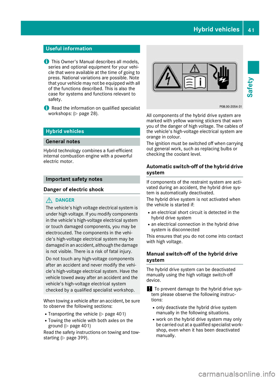
marked with yellow warning stickers that warn
you of the danger of high voltage. The cables of
the vehicle's high-voltage electrical system are
orange in colour.
The ignition must be switched off when carrying out general work, such as replacing bulbs or
checking the coolant level.
Automatic switch-off of the hybrid drive system If components of the restraint system are acti-
vated during an accident, the hybrid drive sys-
tem is automatically deactivated.
The hybrid drive system is not activated when
the vehicle is started if:
R an electrical short circuit is detected in the
hybrid drive system
R an electrical connection in the hybrid drive
system is disconnected
This ensures that you do not come into contact with high voltage.
Manual switch-off of the hybrid drive
system The hybrid drive system can be deactivated
manually using the high voltage switch-off
device.
! To prevent damage to the hybrid drive sys-
tem please observe the following instruc-
tions:
R only deactivate the hybrid drive system
manually in the following situations.
R work on the hybrid drive system may only
be carried out at a qualified specialist work- shop, even when it has been deactivated
manually. Hybrid vehicles
41Safety Z
Page 61 of 453
Using the radar sensor system, PRE-SAFE
®
PLUS is able to detect that a head-on or rear-end
collision is imminent. In certain hazardous sit-
uations, PRE-SAFE ®
PLUS takes pre-emptive
measures to protect the vehicle occupants.
Important safety notes The intervention of PRE-SAFE
®
PLUS cannot
prevent an imminent collision.
The driver is not warned before the intervention
of PRE-SAFE ®
PLUS.
PRE-SAFE ®
PLUS does not intervene:
R if the vehicle is reversing
R when the vehicle is towing a trailer and there
is a risk of a rear-end collision
When driving, or when parking or exiting a park- ing space with assistance from Active Parking
Assist, PRE-SAFE ®
PLUS will not apply the
brakes.
Function PRE-SAFE
®
PLUS intervenes in certain situa-
tions if the radar sensor system detects an
imminent head-on or rear-end collision.
PRE-SAFE ®
PLUS takes the following measures
depending on the hazardous situation detected:
R if the radar sensor system detects that a
head-on collision is imminent, the seat belts
are pre-tensioned
R if the radar sensor system detects that a rear-
end collision is imminent:
- the rear hazard warning lamps are activa-
ted and flash at a higher frequency
- the brake pressure is increased if the driver
applies the brakes when the vehicle is sta-
tionary
- the seat belts are pre-tensioned.
The PRE-SAFE ®
PLUS braking application is can-
celled:
R if the accelerator pedal is depressed when a
gear is engaged
R if the risk of a collision passes or is no longer
detected
R if DISTRONIC PLUS indicates an intention to
pull away
If the hazardous situation passes without result- ing in an accident, the original settings are
restored. Automatic measures after an acci-
dent
Immediately after an accident, the following
measures may be implemented, depending on
the type and severity of the impact:
R the hazard warning lamps are activated
R the emergency lighting is activated
R the vehicle doors are unlocked
R the front side windows are lowered
R vehicles with a memory function: the electri-
cally adjustable steering wheel is raised
R the engine is switched off and the fuel supply
is cut off
R vehicles with the Mercedes-Benz emergency
call system: automatic emergency call
R vehicles with the hybrid drive system: the
hybrid system and the high-voltage electrical
system are deactivated Children in the vehicle
Important safety notes
Accident statistics show that children secured
in the rear seats are safer than children secured in the front-passenger seat. For this reason,
Mercedes-Benz strongly advises that you install
a child restraint system on a rear seat. Children
are generally better protected there.
If a child younger than twelve years old and
under 1.50 m in height is travelling in the vehi-
cle:
R always secure the child in a child restraint
system suitable for Mercedes-Benz vehicles.
The child restraint system must be appropri-
ate to the age, weight and size of the child.
R be sure to observe the instructions and safety
notes in this section in addition to the child
restraint system manufacturer's installation
instructions.
R always pay attention to the instructions and
safety notes on the automatic front-
passenger front airbag deactivation system
(Y page 51). 58
Children in the vehicleSafety
Page 62 of 453
G
WARNING
If you leave children unattended in the vehi-
cle, they may be able to set the vehicle in
motion if, for example, they:
R release the parking brake
R shift the automatic transmission out of park
position P
R start the engine
In addition, they may operate vehicle equip-
ment and become trapped. There is a risk of
an accident and injury.
When leaving the vehicle, always take the key
with you and lock the vehicle. Never leave
children unattended in the vehicle. G
WARNING
If persons (particularly children) are exposed
to heat or cold for a prolonged period, there is a risk of serious or even fatal injuries. Never
leave persons (particularly children) unatten-
ded in the vehicle. G
WARNING
If the child restraint system is placed in direct sunlight, the parts could become very hot.
Children could be suffer burns by touching
these parts, in particular on the metallic parts
of the child restraint system. There is a risk of injury.
If you and your child leave the vehicle, always
make sure that the child restraint system is
not in direct sunlight. Cover it with a blanket, for example. If the child restraint system has
been exposed to direct sunlight, leave it to
cool down before securing the child in it.
Never leave children unattended in the vehi-
cle.
Always ensure that all vehicle occupants have
their seat belts fastened correctly and are sitting
properly. Particular attention must be paid to
children.
Observe the safety notes on the seat belt
(Y page 45) and the information on the correct
use of the seat belt (Y page 46). Child restraint system
If you fit a rearward-facing child restraint system
to the centre rear seat, the rear arm rest must be folded back as far as possible.
Observe the instructions for correct use of the
child restraint system (Y page 63).
For safety reasons, Mercedes-Benz recom-
mends that you only use a child restraint system recommended by Mercedes-Benz
(Y page 67). G
WARNING
If the child restraint system is incorrectly fit-
ted on the seat position suitable for this pur-
pose, it cannot perform its intended protec-
tive function. In the event of an accident,
sharp braking or a sudden change in direction, the child may not be held securely. There is an
increased risk of serious or even fatal injuries.
Observe the manufacturer's installation
instructions and the correct use for the child
restraint system. Make sure that the entire
surface of the child restraint system is resting
on the seat surface. Never place objects
under or behind the child restraint system,
e.g. cushions. Only use child restraint sys-
tems with the original cover designed for
them. Only replace damaged covers with gen- uine covers. G
WARNING
If the child restraint system is fitted incor-
rectly or is not secured, it can come loose in
the event of an accident, heavy braking or a
sudden change in direction. The child
restraint system could be thrown about, strik- ing vehicle occupants. There is an increased
risk of injury, possibly even fatal.
Always fit child restraint systems properly,
even if they are not being used. Make sure
that you observe the child restraint system
manufacturer's installation instructions.
You will find further information on stowing
objects, luggage and loads securely under
"Loading guidelines" (Y page 351). Children in the vehicle
59Safety Z
Page 172 of 453
X
If the transmission is in position Dor N: push
the DIRECT SELECT lever up past the first
point of resistance.
X If the transmission is in position P: depress
the brake pedal and push the DIRECT SELECT lever up past the first point of resistance.
Shifting to neutral N G
WARNING
If children are left unsupervised in the vehicle, they can:
R open doors and endanger other persons or
road users
R climb out and be injured by the traffic
R operate vehicle equipment and, for exam-
ple, trap themselves.
Children could also set the vehicle in motion, for example by:
R releasing the parking brake
R shifting the automatic transmission out of
park position P
R starting the engine.
There is a risk of an accident and injury.
When leaving the vehicle, always take the key
with you and lock the vehicle. Never leave
children unattended in the vehicle. Always
keep the key out of reach of children.
X If the transmission is in position Dor R: push
the DIRECT SELECT lever up or down to the
first point of resistance.
X If the transmission is in position P: depress
the brake pedal and push the DIRECT SELECT
lever up or down to the first point of resist-
ance.
If you switch the engine off with the transmis-
sion in position Ror D, the automatic transmis-
sion shifts to Nautomatically.
With the key: if you then open the driver's door
or the front-passenger door or remove the key
from the ignition, the automatic transmission
shifts to Pautomatically.
With the Start/Stop button: if you then open
the driver's door or the front-passenger door,
the automatic transmission shifts to Pautomat-
ically. If you want the automatic transmission to
remain in neutral
N, e.g. when having the vehicle
cleaned in an automatic car wash with a towing
system:
With the key:
X Switch the ignition on.
X Depress the brake pedal and keep it
depressed.
X Shift to neutral N.
X Release the brake pedal.
X Release the electric parking brake.
X Switch off the ignition and leave the key in the
ignition lock.
With the Start/Stop button: X Remove the Start/Stop button from the igni-
tion lock.
X Insert the key into the ignition lock.
X Switch the ignition on.
X Depress the brake pedal and keep it
depressed.
X Shift to neutral N.
X Release the brake pedal.
X Release the electric parking brake.
X Switch off the ignition and leave the key in the
ignition lock.
Engaging drive position D X
If the transmission is in position Ror N: push
the DIRECT SELECT lever down past the first
point of resistance.
X If the transmission is in position P: depress
the brake pedal and push the DIRECT SELECT lever down past the first point of resistance. Automatic transmission
169Driving and parking Z
Page 174 of 453
R
the type of road is suitable, e.g. no steep gra-
dients
R you are no longer depressing the accelerator
pedal
Gliding mode is deactivated under the following
conditions:
R you depress the accelerator pedal
R you depress the brake pedal
R you use the DIRECT SELECT lever to switch
the transmission position (Y page 168)
R you use the DYNAMIC SELECT controller to
change the drive program (Y page 166)
R you activate manual gearshifting
(Y page 172)
R you leave the suitable speed range
Mercedes-AMG vehicles Gliding mode is characterised by the following:
R the combustion engine is disconnected from
the drive train
R the engine speed is equal to the engine idling
speed
R in the multifunction display, the gliding sym-
bol appears in the drive program display
Gliding mode can be activated under the follow-
ing conditions:
R the Comfort drive program is activated or you
select the "Comfort" setting for the drive sys-
tem within the Individualdrive program. You
can find information about this in the Digital
Owner's Manual
R the ECO start/stop function is activated
R you are driving carefully with low acceleration
of the vehicle
R the engine is at normal operating temperature
R the speed is within a suitable range
R the type of road is suitable, e.g. no steep gra-
dients
R you are no longer depressing the accelerator
pedal
Gliding mode is deactivated under the following conditions:
R you have deactivated the ECO start/stop
function
R you depress the accelerator pedal
R you depress the brake pedal
R you use the DIRECT SELECT lever to switch
the transmission position (Y page 168)R
you use the DYNAMIC SELECT controller to
change the drive program (Y page 166)
R you activate manual gearshifting
(Y page 172)
R you leave the suitable speed range
Towing a trailer X
Drive in the middle of the engine speed range
on uphill gradients.
X Depending on the uphill or downhill gradient,
use left-hand steering wheel gearshift paddle
(Y page 172) to select a lower gear, even if
cruise control, DISTRONIC PLUS, or SPEED-
TRONIC are activated. Drive programs
Slippery drive program The
Slippery drive program has the following
characteristics:
R reduced engine and transmission settings for
optimum propulsion on slippery or snow-cov-
ered roads.
R optimised ESP ®
stability control on slippery
or snow-covered roads.
R the vehicle has improved driving stability on
slippery or snow-covered roads, for example.
Comfort drive program The
Comfort drive program has the following
characteristics:
R comfort-orientated engine and transmission
settings.
R optimal fuel consumption resulting from the
automatic transmission shifting up sooner.
R the vehicle pulling away more gently in
forward and reverse gears unless the accel-
erator pedal is depressed fully.
R the automatic transmission shifting up
sooner. This results in the vehicle being driven
at lower engine speeds and the wheels being less likely to spin. Automatic transmission
171Driving and parking Z
Page 188 of 453
Heat generated by the charging cable
and charging cable connector Observe the "Important safety notes"
(Y
page 182).
During the charging process, the charging cable
and charging cable connector may heat up.
The charging cable and the charging cable con- nector will only heat up within the permissible
limiting values, provided that:
R the mains power supply and the charging
cable are not damaged
R the instructions for handling the charging
cable and controls on the charging cable are
observed
If the charging cable or charging cable connec-
tor become too hot, have the mains power sup- ply checked.
Protection against overvoltage !
Voltage surges in the mains supply can dam-
age the vehicle. The vehicle is therefore
equipped with a device which protects it from
voltage surges in the mains supply. This
device may be triggered during severe thun-
derstorms, for example, and may lead to the
building's fuse being tripped and an interrup-
tion in the power supply. These functions pro-
tect the vehicle. After the building fuse is
switched on again, the charging process
resumes automatically. Following an interrup-
tion in the power supply or tripping of the
building's fuse, it may take up to 10 minutes
for charging to resume automatically.
Reset the building's circuit breaker. Otherwise,
the charging process cannot be continued.
General information on the charging
process Observe the "Important safety notes"
(Y page 182).
The vehicle socket is located in the rear bumper on the right below the tail lamp.
The charge socket flap and the vehicle are cen-
trally locked or unlocked simultaneously. Charging the high-voltage battery via
the mains socket
Charging cable for mains sockets Important safety notes
! Only use the charging cable to charge the
high-voltage battery. Do not use the charging cable for other purposes. It may otherwise be damaged.
The vehicle is supplied with a country-specific
charging cable, variant 1 or variant 2, for con-
nection to a mains socket. The controls of the
two charging cable variants are different. Only
use the charging cable supplied with the vehicle
or a charging cable approved for the vehicle.
i The charging process can vary depending on
the mains power supply. Therefore, always
observe the local information.
i For short charge times (charging with 16
A),
connect the fast-charging cable to a wallbox
or charging station without a preinstalled
cable. You can also use the optionally availa-
ble charging cable with the CE plug.
Information about charging from a wallbox
(Y page 188).
Information about charging from a charging sta-
tion (Y page 189).
Stowing the charging cable The charging cable can be stowed and secured
in the bag provided in the luggage compartment
of the vehicle.
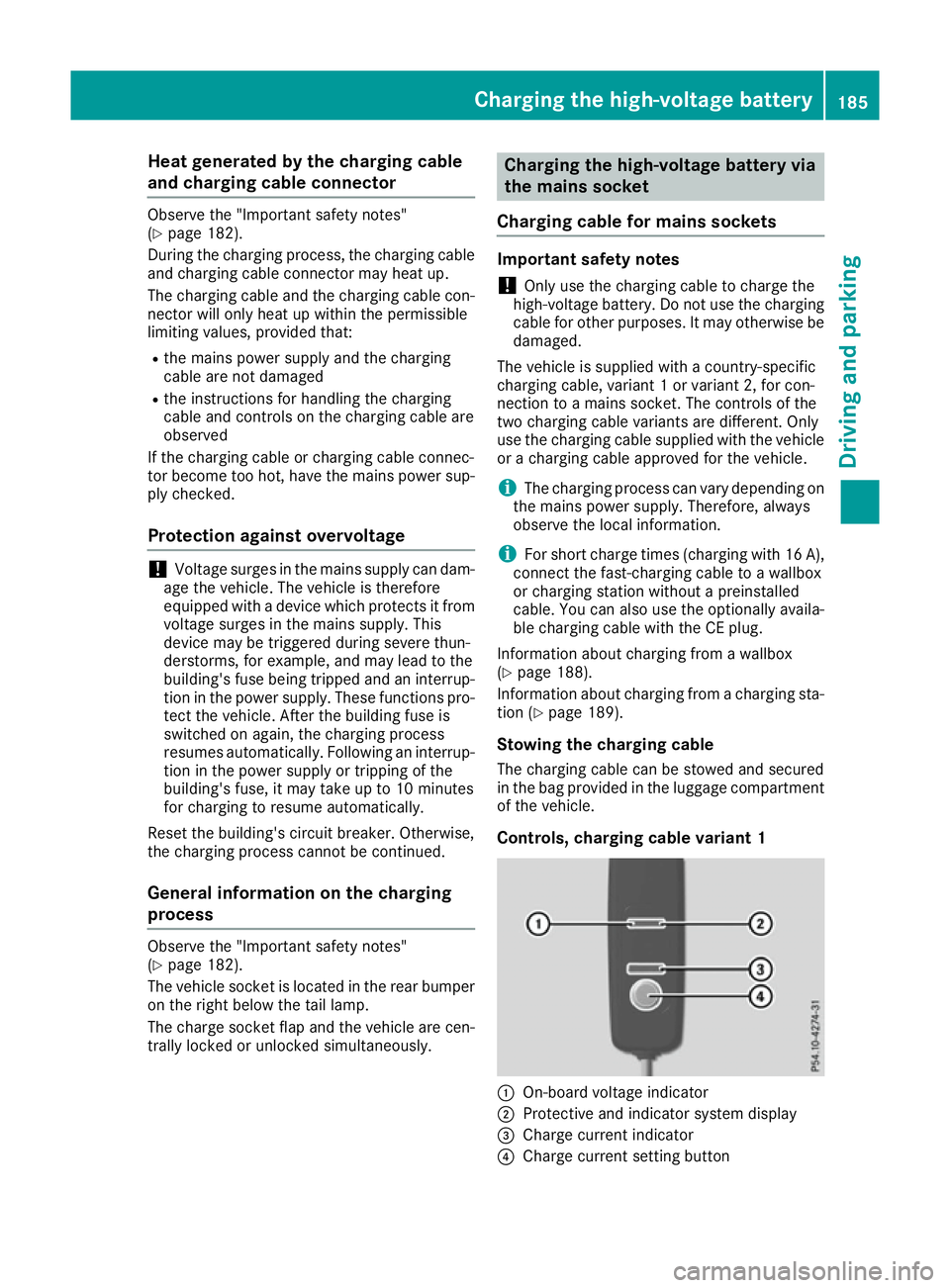
Controls, charging cable variant 1 :
On-board voltage indicator
; Protective and indicator system display
= Charge current indicator
? Charge current setting button Charging the high-voltage battery
185Driving and parking Z