2015 MERCEDES-BENZ GLE SUV clock
[x] Cancel search: clockPage 180 of 453
Opening the fuel filler flap (except
PLUG-IN HYBRID vehicles)
:
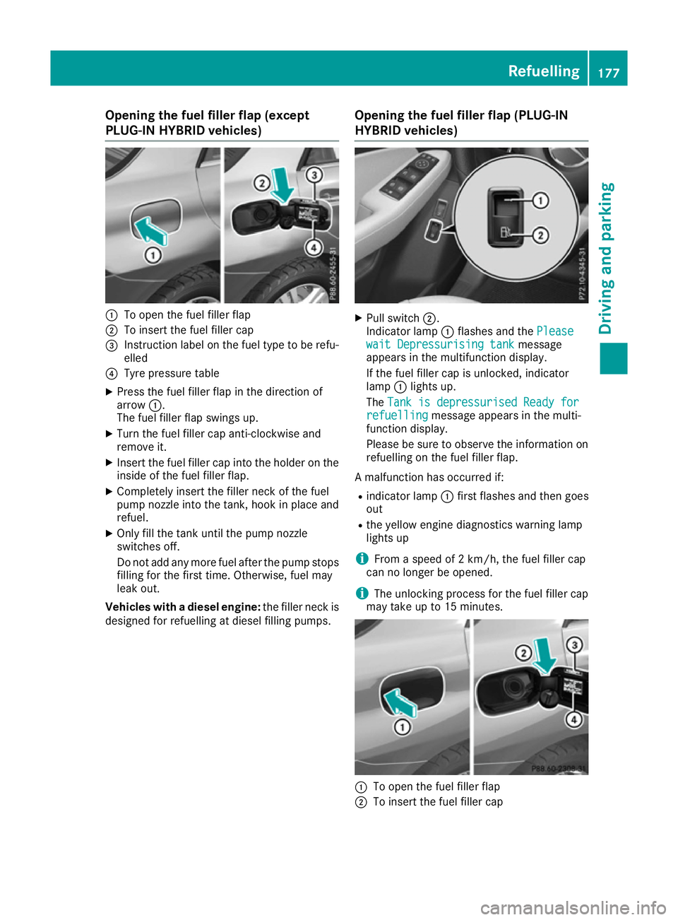
To open the fuel filler flap
; To insert the fuel filler cap
= Instruction label on the fuel type to be refu-
elled
? Tyre pressure table
X Press the fuel filler flap in the direction of
arrow :.
The fuel filler flap swings up.
X Turn the fuel filler cap anti-clockwise and
remove it.
X Insert the fuel filler cap into the holder on the
inside of the fuel filler flap.
X Completely insert the filler neck of the fuel
pump nozzle into the tank, hook in place and
refuel.
X Only fill the tank until the pump nozzle
switches off.
Do not add any more fuel after the pump stops filling for the first time. Otherwise, fuel may
leak out.
Vehicles with a diesel engine: the filler neck is
designed for refuelling at diesel filling pumps. Opening the fuel filler flap (PLUG-IN
HYBRID vehicles) X
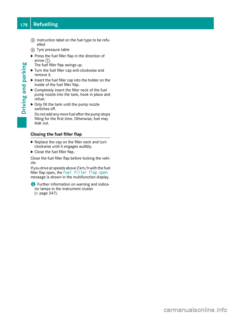
Pull switch ;.
Indicator lamp :flashes and the Please Please
wait Depressurising tank
wait Depressurising tank message
appears in the multifunction display.
If the fuel filler cap is unlocked, indicator
lamp :lights up.
The Tank is depressurised Ready for Tank is depressurised Ready for
refuelling
refuelling message appears in the multi-
function display.
Please be sure to observe the information on refuelling on the fuel filler flap.
A malfunction has occurred if:
R indicator lamp :first flashes and then goes
out
R the yellow engine diagnostics warning lamp
lights up
i From a speed of 2 km/h, the fuel filler cap
can no longer be opened.
i The unlocking process for the fuel filler cap
may take up to 15 minutes. :
To open the fuel filler flap
; To insert the fuel filler cap Refuelling
177Driving and parking Z
Page 181 of 453
=
Instruction label on the fuel type to be refu-
elled
? Tyre pressure table
X Press the fuel filler flap in the direction of
arrow :.
The fuel filler flap swings up.
X Turn the fuel filler cap anti-clockwise and
remove it.
X Insert the fuel filler cap into the holder on the
inside of the fuel filler flap.
X Completely insert the filler neck of the fuel
pump nozzle into the tank, hook in place and
refuel.
X Only fill the tank until the pump nozzle
switches off.
Do not add any more fuel after the pump stops
filling for the first time. Otherwise, fuel may
leak out.
Closing the fuel filler flap X
Replace the cap on the filler neck and turn
clockwise until it engages audibly.
X Close the fuel filler flap.
Close the fuel filler flap before locking the vehi-
cle.
If you drive at speeds above 2 km/h with the fuel
filler flap open, the Fuel filler flap open
Fuel filler flap open
message is shown in the multifunction display.
i Further information on warning and indica-
tor lamps in the instrument cluster
(Y page 347). 178
RefuellingDriving and parking
Page 184 of 453
AdBlue
®
tank any further. AdBlue ®
may leak
out.
To avoid transporting already opened refill con-
tainers in the vehicle, completely empty refill
bottles or canisters when filling the AdBlue ®
tank, if possible.
Further information on AdBlue ®
(Y page 439).
Opening the AdBlue ®
filler cap The fuel filler flap is unlocked or locked auto-
matically when you open or close the vehicle
with the key or using KEYLESS-GO.
X Switch the ignition off.
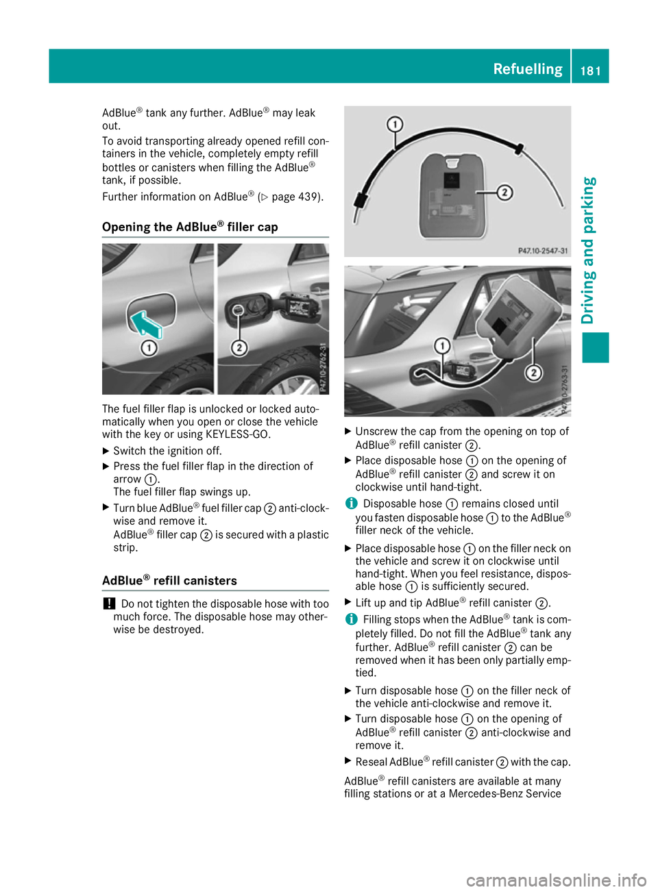
X Press the fuel filler flap in the direction of
arrow :.
The fuel filler flap swings up.
X Turn blue AdBlue ®
fuel filler cap ;anti-clock-
wise and remove it.
AdBlue ®
filler cap ;is secured with a plastic
strip.
AdBlue ®
refill canisters !
Do not tighten the disposable hose with too
much force. The disposable hose may other-
wise be destroyed. X
Unscrew the cap from the opening on top of
AdBlue ®
refill canister ;.
X Place disposable hose :on the opening of
AdBlue ®
refill canister ;and screw it on
clockwise until hand-tight.
i Disposable hose
:remains closed until
you fasten disposable hose :to the AdBlue ®
filler neck of the vehicle.
X Place disposable hose :on the filler neck on
the vehicle and screw it on clockwise until
hand-tight. When you feel resistance, dispos-
able hose :is sufficiently secured.
X Lift up and tip AdBlue ®
refill canister ;.
i Filling stops when the AdBlue ®
tank is com-
pletely filled. Do not fill the AdBlue ®
tank any
further. AdBlue ®
refill canister ;can be
removed when it has been only partially emp-
tied.
X Turn disposable hose :on the filler neck of
the vehicle anti-clockwise and remove it.
X Turn disposable hose :on the opening of
AdBlue ®
refill canister ;anti-clockwise and
remove it.
X Reseal AdBlue ®
refill canister ;with the cap.
AdBlue ®
refill canisters are available at many
filling stations or at a Mercedes-Benz Service Refuelling
181Driving and parking Z
Page 185 of 453
Centre. AdBlue
®
refill canisters are often sold
with a filler hose. A filler hose that does not
exactly fit the vehicle's AdBlue ®
tank offers no
protection against overfilling. AdBlue ®
may leak
out as a result of overfilling. Mercedes-Benz
offers a special disposable hose with overfill
protection. You can obtain this from any
Mercedes-Benz Service Centre. AdBlue ®
is
available in a variety of containers and recepta- cles. Only use the disposable hose with the
Mercedes-Benz AdBlue ®
refill canisters.
AdBlue ®
refill bottle !
Screw on the AdBlue ®
refill bottle only hand-
tight. It may otherwise be destroyed. X
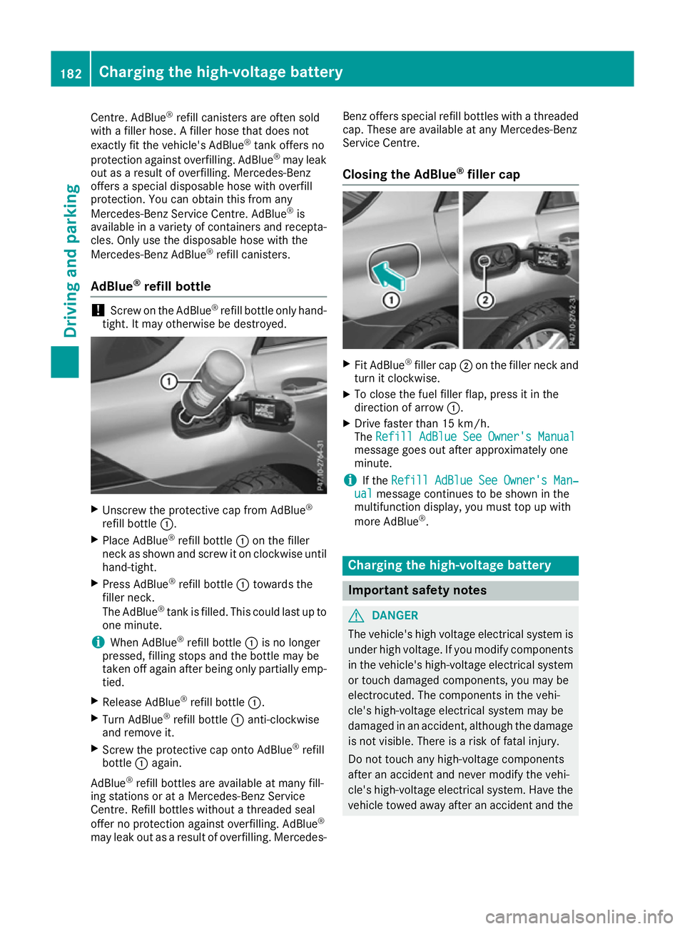
Unscrew the protective cap from AdBlue ®
refill bottle :.
X Place AdBlue ®
refill bottle :on the filler
neck as shown and screw it on clockwise until hand-tight.
X Press AdBlue ®
refill bottle :towards the
filler neck.
The AdBlue ®
tank is filled. This could last up to
one minute.
i When AdBlue ®
refill bottle :is no longer
pressed, filling stops and the bottle may be
taken off again after being only partially emp- tied.
X Release AdBlue ®
refill bottle :.
X Turn AdBlue ®
refill bottle :anti-clockwise
and remove it.
X Screw the protective cap onto AdBlue ®
refill
bottle :again.
AdBlue ®
refill bottles are available at many fill-
ing stations or at a Mercedes-Benz Service
Centre. Refill bottles without a threaded seal
offer no protection against overfilling. AdBlue ®
may leak out as a result of overfilling. Mercedes- Benz offers special refill bottles with a threaded
cap. These are available at any Mercedes-Benz
Service Centre.
Closing the AdBlue ®
filler cap X
Fit AdBlue ®
filler cap ;on the filler neck and
turn it clockwise.
X To close the fuel filler flap, press it in the
direction of arrow :.
X Drive faster than 15 km/h.
The Refill AdBlue See Owner's Manual Refill AdBlue See Owner's Manual
message goes out after approximately one
minute.
i If the
Refill AdBlue See Owner's Man‐ Refill AdBlue See Owner's Man‐
ual
ual message continues to be shown in the
multifunction display, you must top up with
more AdBlue ®
. Charging the high-voltage battery
Important safety notes
G
DANGER
The vehicle's high voltage electrical system is under high voltage. If you modify components
in the vehicle's high-voltage electrical system or touch damaged components, you may be
electrocuted. The components in the vehi-
cle's high-voltage electrical system may be
damaged in an accident, although the damage
is not visible. There is a risk of fatal injury.
Do not touch any high-voltage components
after an accident and never modify the vehi-
cle's high-voltage electrical system. Have the vehicle towed away after an accident and the 182
Charging the high-voltage batteryDriving and parking
Page 220 of 453
vehicle's speed is not adapted to the road
conditions. There is a risk of an accident.
Always adapt your speed and driving style to
the vehicle's driving characteristics and to the prevailing road and weather conditions.
! When driving on extremely rough terrain,
select a high vehicle level in good time. Make
sure there is always sufficient ground clear-
ance. You will otherwise damage the vehicle.
R SUVs overturn considerably more often than
other vehicle types.
If this vehicle is not driven in a safe manner, it can lead to an accident, to the vehicle over-
turning as well as serious or even fatal inju-
ries.
R In the event of an accident with the vehicle
overturning, passengers who are not wearing
their seat belt are considerably more likely to die than passengers wearing their seat belt.
You and all vehicle occupants should always
wear your seat belts.
Basic settings The extent to which the vehicle is raised or low-
ered depends on the basic setting selected.
Select:
R the Comfort orSport drive program for driv-
ing on normal roads
R the Offroad drive program for driving on eas-
ily negotiable off-road terrain
R the Offroad Plus drive program for off-road
driving
R Offroad level 1 for driving on easily negotiable
off-road terrain
R Offroad level 2 for driving on normal off-road
terrain
R Offroad level 3 for freeing the vehicle from
especially difficult off-road terrain at low
speeds
The individual vehicle levels differ from the nor- mal level as follows:
R –15 mm in the Sportdrive program
R +/–0 mm in the Comfortdrive program
R + 30 mm in the Offroaddrive program
R + 60 mm in the Offroad Plusdrive program
R + 30 mm in offroad level 1 R
+ 60 mm in offroad level 2
R + 90 mm in offroad level 3
Setting the vehicle level !
Make sure there is enough ground clear-
ance when the vehicle is being lowered. It
could otherwise hit the ground, damaging the
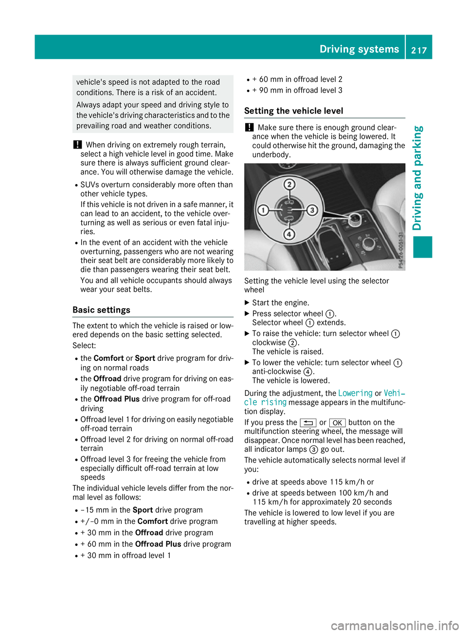
underbody. Setting the vehicle level using the selector
wheel
X Start the engine.
X Press selector wheel :.
Selector wheel :extends.
X To raise the vehicle: turn selector wheel :
clockwise ;.
The vehicle is raised.
X To lower the vehicle: turn selector wheel :
anti-clockwise ?.
The vehicle is lowered.
During the adjustment, the Lowering LoweringorVehi‐
Vehi‐
cle
cle rising
rising message appears in the multifunc-
tion display.
If you press the %ora button on the
multifunction steering wheel, the message will
disappear. Once normal level has been reached, all indicator lamps =go out.
The vehicle automatically selects normal level if
you:
R drive at speeds above 115 km/h or
R drive at speeds between 100 km/h and
115 km/h for approximately 20 seconds
The vehicle is lowered to low level if you are
travelling at higher speeds. Driving systems
217Driving and parking Z
Page 221 of 453
Normal level
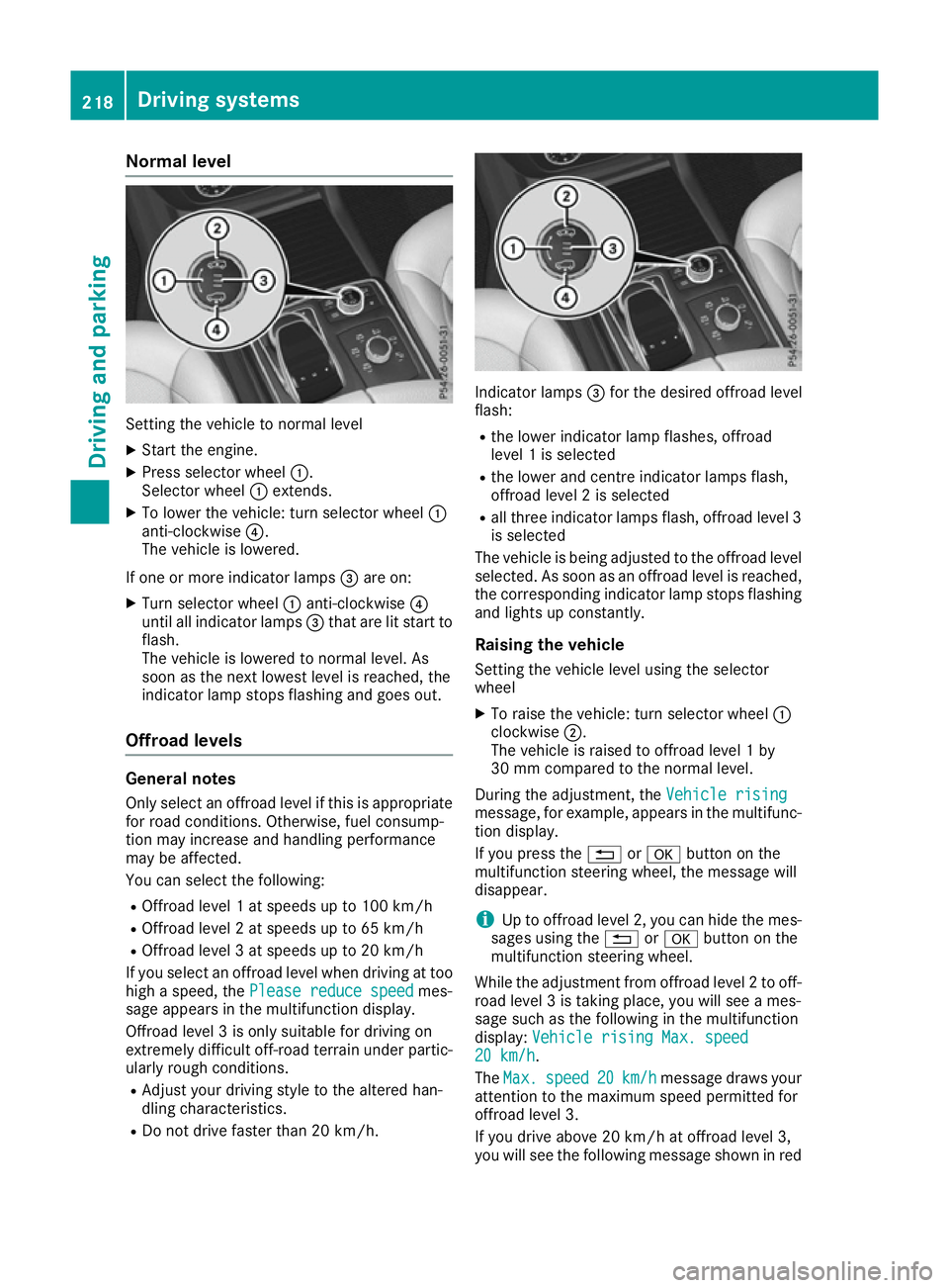
Setting the vehicle to normal level
X Start the engine.
X Press selector wheel :.
Selector wheel :extends.
X To lower the vehicle: turn selector wheel :
anti-clockwise ?.
The vehicle is lowered.
If one or more indicator lamps =are on:
X Turn selector wheel :anti-clockwise ?
until all indicator lamps =that are lit start to
flash.
The vehicle is lowered to normal level. As
soon as the next lowest level is reached, the
indicator lamp stops flashing and goes out.
Offroad levels General notes
Only select an offroad level if this is appropriate for road conditions. Otherwise, fuel consump-
tion may increase and handling performance
may be affected.
You can select the following:
R Offroad level 1 at speeds up to 100 km/h
R Offroad level 2 at speeds up to 65 km/h
R Offroad level 3 at speeds up to 20 km/h
If you select an offroad level when driving at too
high a speed, the Please reduce speed
Please reduce speed mes-
sage appears in the multifunction display.
Offroad level 3 is only suitable for driving on
extremely difficult off-road terrain under partic- ularly rough conditions.
R Adjust your driving style to the altered han-
dling characteristics.
R Do not drive faster than 20 km/h. Indicator lamps
=for the desired offroad level
flash:
R the lower indicator lamp flashes, offroad
level 1 is selected
R the lower and centre indicator lamps flash,
offroad level 2 is selected
R all three indicator lamps flash, offroad level 3
is selected
The vehicle is being adjusted to the offroad level
selected. As soon as an offroad level is reached,
the corresponding indicator lamp stops flashing and lights up constantly.
Raising the vehicle
Setting the vehicle level using the selector
wheel
X To raise the vehicle: turn selector wheel :
clockwise ;.
The vehicle is raised to offroad level 1 by
30 mm compared to the normal level.
During the adjustment, the Vehicle rising Vehicle rising
message, for example, appears in the multifunc-
tion display.
If you press the %ora button on the
multifunction steering wheel, the message will
disappear.
i Up to offroad level 2, you can hide the mes-
sages using the %ora button on the
multifunction steering wheel.
While the adjustment from offroad level 2 to off-
road level 3 is taking place, you will see a mes-
sage such as the following in the multifunction
display: Vehicle rising Max. speed
Vehicle rising Max. speed
20 km/h 20 km/h.
The Max. Max. speed
speed 20
20km/h
km/h message draws your
attention to the maximum speed permitted for
offroad level 3.
If you drive above 20 km/h at offroad level 3,
you will see the following message shown in red 218
Driving systemsDriving an
d parking
Page 281 of 453
The trailer battery may not be charged from
the power supply.
When it leaves the factory, your vehicle's trailer
socket is equipped with a permanent power
supply and a power supply that is switched on
via the ignition lock.
The permanent power supply is supplied via
trailer socket pin 9.
The power supply that is switched on via the
ignition lock is supplied via trailer socket pin 10.
The trailer's permanent power supply is
switched off in the event of low vehicle supply
voltage and after six hours at the latest.
You can find more information about fitting the
trailer electrics at a qualified specialist work-
shop.
X To switch the connected power supply on
or off: turn the key to position 2or 0respec-
tively (Y page 158). Failure check for LEDs
If LED lamps are fitted in the trailer, a malfunc-
tion message may appear in the multifunction
display even if there is no fault. The reason for
the error message may be that the current has
fallen below the minimum of 50 mA.
To ensure reliable indication of the failure, each LED chain in the trailer lighting must be guaran-
teed a minimum current of 50 mA. Trailer with 7-pin connector
General notes Trailer with 7-pin connector:
you can connect
to the 13-pin socket on the ball coupling using
an adapter or, if necessary, an adapter cable.
Both can be obtained at a qualified specialist
workshop.
Fitting the adapter !
Make sure that there is sufficient cable play
so that the cable cannot become detached
when cornering.
! Remove the adapter cable before folding in
the ball coupling. You could otherwise dam-
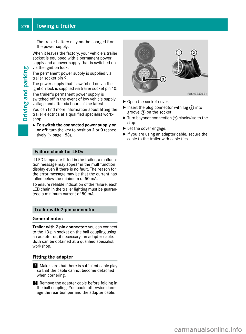
age the rear bumper and the adapter cable. X
Open the socket cover.
X Insert the plug connector with lug :into
groove =on the socket.
X Turn bayonet connection ;clockwise to the
stop.
X Let the cover engage.
X If you are using an adapter cable, secure the
cable to the trailer with cable ties. 278
Towing a trailerDriving and parking
Page 284 of 453
Useful information
i This Owner's Manual describes all models,
series and optional equipment for your vehi-
cle that were available at the time of going to
press. National variations are possible. Note
that your vehicle may not be equipped with all
of the functions described. This is also the
case for systems and functions relevant to
safety.
i Read the information on qualified specialist
workshops: (Y page 28). Important safety notes
G
WARNING
Operating the integrated information systems and communications equipment in the vehicle
while driving will distract you from traffic con-
ditions. You could then lose control of the
vehicle. There is a risk of an accident.
Only operate these devices if road traffic con-
ditions permit. If you are unsure about the
surrounding conditions, pull over to a safe
location and make entries only while the vehi-
cle is stationary.
You must observe the legal requirements for the country in which you are currently driving whenoperating the on-board computer.
PLUG-IN HYBRID vehicles only: G
WARNING
If the instrument cluster has failed or there is a malfunction, you may not know about
safety-related function restrictions. The oper-ating safety of your vehicle may be affected.
There is a risk of an accident.
Immediately stop the vehicle while paying
attention to the traffic conditions and consult
a qualified specialist workshop.
All vehicles, except PLUG-IN HYBRID vehi-
cles:
The on-board computer only shows messages or warnings from certain systems in the multifunc-
tion display. You should therefore make sure
your vehicle is operating safely at all times. For an overview, see the instrument cluster illus-
tration (Y page 32). Displays and operation
Instrument cluster lighting
The lighting in the instrument cluster, in the dis- plays and the controls in the vehicle interior can
be adjusted using the brightness control knob.
The brightness control knob is located on the
bottom left of the instrument cluster
(Y page 32).
X Turn the brightness control knob clockwise or
anti-clockwise.
If you turn the light switch to Ã,Tor
L, the brightness is dependent upon the
brightness of the ambient light.
i The light sensor in the instrument cluster
automatically controls the brightness of the
multifunction display.
In daylight, the displays in the instrument
cluster are not illuminated. Speedometer with segments
The speedometer is divided into segments only
on vehicles with DISTRONIC PLUS.
The segments in the speedometer indicate
which speed range is available.
R Variable SPEEDTRONIC activated
(Y page 205):
The segments light up from the start of the
scale to the selected limit speed.
R DISTRONIC PLUS activated (Y page 207):
One or two segments in the set speed range
light up.
R DISTRONIC PLUS detects a vehicle in front
moving more slowly than the stored speed:
The segments between the speed of the vehi- cle in front and the stored speed light up. Rev counter
! Do not drive in the overrevving range. Doing
so will damage the engine.
The red band in the rev counter indicates the
engine's overrevving range. Displays and operation
281On-board computer and displays Z