2015 MERCEDES-BENZ GLE SUV ESP
[x] Cancel search: ESPPage 353 of 453
Tyres
Warning/
indicator
lamp
N N
Signal type
Possible causes/consequences and M
MSolutions h
N
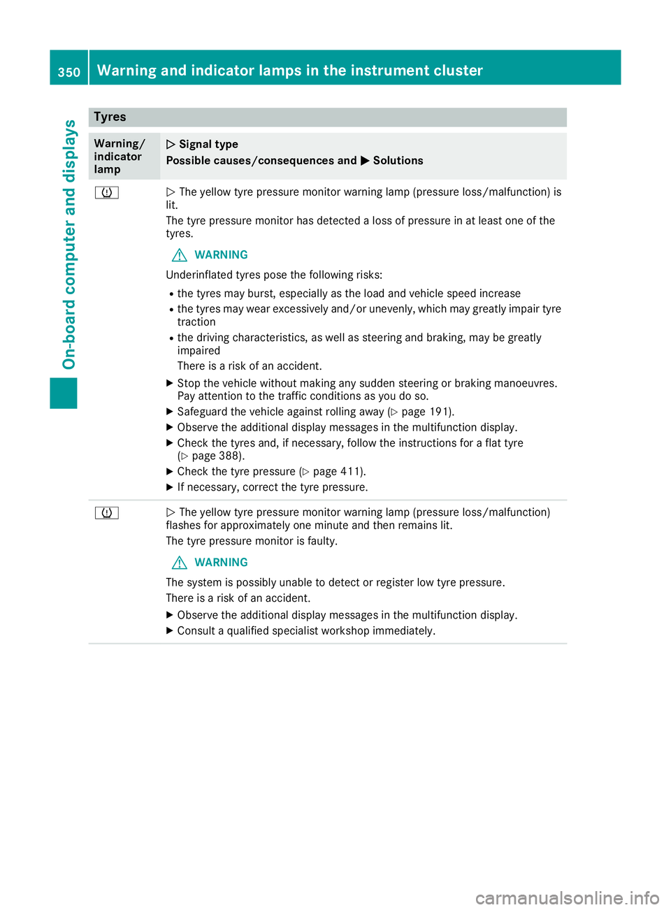
The yellow tyre pressure monitor warning lamp (pressure loss/malfunction) is
lit.
The tyre pressure monitor has detected a loss of pressure in at least one of the
tyres.
G WARNING
Underinflated tyres pose the following risks:
R the tyres may burst, especially as the load and vehicle speed increase
R the tyres may wear excessively and/or unevenly, which may greatly impair tyre
traction
R the driving characteristics, as well as steering and braking, may be greatly
impaired
There is a risk of an accident.
X Stop the vehicle without making any sudden steering or braking manoeuvres.
Pay attention to the traffic conditions as you do so.
X Safeguard the vehicle against rolling away (Y page 191).
X Observe the additional display messages in the multifunction display.
X Check the tyres and, if necessary, follow the instructions for a flat tyre
(Y page 388).
X Check the tyre pressure (Y page 411).
X If necessary, correct the tyre pressure. h
N
The yellow tyre pressure monitor warning lamp (pressure loss/malfunction)
flashes for approximately one minute and then remains lit.
The tyre pressure monitor is faulty.
G WARNING
The system is possibly unable to detect or register low tyre pressure.
There is a risk of an accident.
X Observe the additional display messages in the multifunction display.
X Consult a qualified specialist workshop immediately. 350
Warning and indicator lamps in the instrument clusterOn-board computer and displays
Page 354 of 453
Useful information
i This Owner's Manual describes all models,
series and optional equipment for your vehi-
cle that were available at the time of going to
press. National variations are possible. Note
that your vehicle may not be equipped with all
of the functions described. This is also the
case for systems and functions relevant to
safety.
i Read the information on qualified specialist
workshops: (Y page 28). Stowage areas
Loading guidelines
G
WARNING
If objects, luggage or loads are not secured or not secured sufficiently, they could slip, tip
over or be flung around and thereby hit vehicle
occupants. There is a risk of injury, especially when braking or abruptly changing directions.
Always store objects so that they cannot be
flung around. Secure objects, luggage or
loads against slipping or tipping before the
journey. G
WARNING
Combustion engines emit poisonous exhaust
gases such as carbon monoxide. If the tailgate is open when the engine is running, particu-
larly if the vehicle is moving, exhaust fumes
could enter the passenger compartment.
There is a risk of poisoning.
Turn off the engine before opening the tail-
gate. Never drive with the tailgate open. G
WARNING
The exhaust tail pipe and tail pipe trim can
become very hot. If you come into contact
with these parts of the vehicle, you could burn
yourself. There is a risk of injury.
Always be particularly careful around the
exhaust tail pipe and the tail pipe trim. Allow
these components to cool down before touch-
ing them. The handling characteristics of a laden vehicle
are dependent on the distribution of the load
within the vehicle. For this reason, you should
observe the following notes when transporting a
load:
R never exceed the maximum permissible gross
vehicle weight or the permissible axle loads
for the vehicle (including occupants).
R the luggage compartment is the preferred
place to store objects.
R position heavy loads as far forwards as pos-
sible and as low down in the load compart-
ment as possible.
R the load must not protrude above the upper
edge of the seat backrests.
R always place the load against the rear or front
seat backrests. Make sure that the seat
backrests are securely locked into place.
R always place the load behind unoccupied
seats if possible.
R use the lashing eyelets and the luggage nets
to transport loads and luggage.
R only use lashing eyelets and fastening com-
ponents that are suitable for the weight and
size of the load.
R hook in the safety net when loading.
R secure the load with sufficiently strong and
wear-resistant lashing material. pad sharp
edges for protection.
i Load restraints are available at any qualified
specialist workshop, e.g. a Mercedes-Benz
Service Centre. Stowage compartments
Important safety notes G
WARNING
If you do not correctly store objects in the
vehicle interior, they can slip or be flung
around, thus striking vehicle occupants.
There is a risk of injury, especially when brak- ing or abruptly changing directions. Stowage areas
351Stowing and features
Z
Page 358 of 453
Folding the rear bench seat forwards
If the driver's or front-passenger seat is set for a
larger person, it may not be possible to fold the rear bench seat forwards. In this case, move the
front seats as far forward as possible.
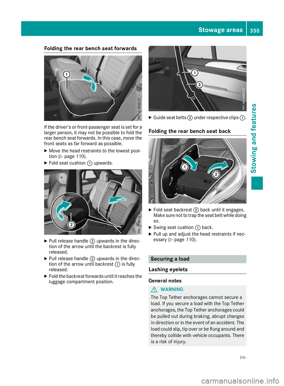
X Move the head restraints to the lowest posi-
tion (Y page 110).
X Fold seat cushion :upwards. X
Pull release handle ;upwards in the direc-
tion of the arrow until the backrest is fully
released.
X Pull release handle ;upwards in the direc-
tion of the arrow until backrest :is fully
released.
X Fold the backrest forwards until it reaches the
luggage compartment position. X
Guide seat belts ;under respective clips :.
Folding the rear bench seat back X
Fold seat backrest ;back until it engages.
Make sure not to trap the seat belt while doing so.
X Swing seat cushion :back.
X Pull up and adjust the head restraints if nec-
essary (Y page 110). Securing a load
Lashing eyelets General notes
G
WARNING
The Top Tether anchorages cannot secure a
load. If you secure a load with the Top Tether
anchorages, the Top Tether anchorages could be pulled out during braking, abrupt changes
in direction or in the event of an accident. The load could slip, tip over or be flung around and
thereby collide with vehicle occupants. There is a risk of injury. Stowage areas
355Stowing and featu res
Z
Page 362 of 453
R
a telescopic rod
R two mounting elements
R two retaining feet
Important safety notes G
WARNING
If you drive when the luggage compartment
floor is open, objects could be flung around,
thus striking vehicle occupants. There is a risk of injury, especially when braking or abruptly
changing directions.
Always close the luggage compartment floor
before a journey.
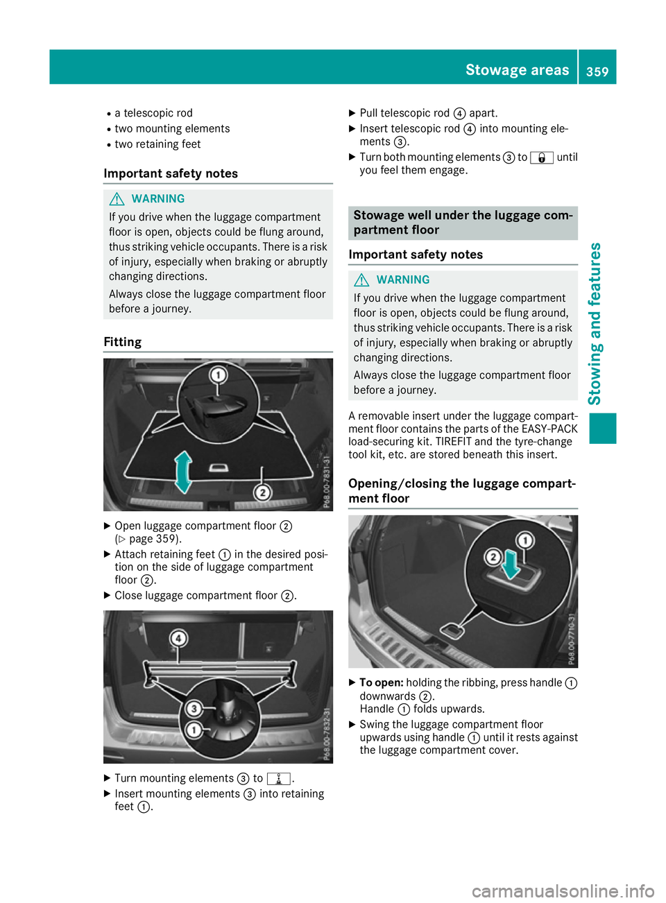
Fitting X
Open luggage compartment floor ;
(Y page 359).
X Attach retaining feet :in the desired posi-
tion on the side of luggage compartment
floor ;.
X Close luggage compartment floor ;.X
Turn mounting elements =to=.
X Insert mounting elements =into retaining
feet :. X
Pull telescopic rod ?apart.
X Insert telescopic rod ?into mounting ele-
ments =.
X Turn both mounting elements =to& until
you feel them engage. Stowage well under the luggage com-
partment floor
Important safety notes G
WARNING
If you drive when the luggage compartment
floor is open, objects could be flung around,
thus striking vehicle occupants. There is a risk of injury, especially when braking or abruptly
changing directions.
Always close the luggage compartment floor
before a journey.
A removable insert under the luggage compart-
ment floor contains the parts of the EASY-PACK load-securing kit. TIREFIT and the tyre-change
tool kit, etc. are stored beneath this insert.
Opening/closing the luggage compart-
ment floor X
To open: holding the ribbing, press handle :
downwards ;.
Handle :folds upwards.
X Swing the luggage compartment floor
upwards using handle :until it rests against
the luggage compartment cover. Stowage areas
359Stowing and features Z
Page 371 of 453
X
Press and hold button Bon remote control
A until indicator lamp :lights up green.
When indicator lamp :lights up green: pro-
gramming is finished.
When indicator lamp :flashes green: pro-
gramming was successful. The next step is to synchronise the rolling code (Y page 368).
X Release button Bof remote control Aof the
garage door drive.
If indicator lamp :lights up red: repeat the
programming process for the corresponding
button on the rear-view mirror. When doing
so, vary the distance between remote control A and the rear-view mirror.
The required distance between remote con-
trol Aand the integrated garage door opener
depends on the garage door drive system.
Several attempts may be required. You
should test every position for at least
25 seconds before trying another position.
Synchronising the rolling code
Observe the "Important safety notes"
(Y page 367).
If the garage door system uses a rolling code,
you will also have to synchronise the garage
door system with the integrated garage door
opener in the rear-view mirror. To do this, you
will need to use the programming button on the door drive control panel. The programming but-
ton may be placed at different locations depend- ing on the manufacturer. It is usually located on
the door drive unit on the garage ceiling.
Familiarise yourself with the garage door drive
operating instructions, e.g. under "Program-
ming of additional remote controls", before car-
rying out the following steps.
Your vehicle must be within range of the garage
door or gate opener drive. Make sure that nei-
ther your vehicle nor any persons/objects are
present within the sweep of the door or gate.
X Turn the key to position 2in the ignition lock
(Y page 158).
X Get out of the vehicle.
X Press the programming button on the door
drive unit.
Usually, you now have 30 seconds to initiate
the next step. X
Get into the vehicle.
X Press previously programmed button ;,=
or ? of the integrated garage door opener
until the door closes.
The rolling code synchronisation is then com- plete.
Problems when programming
If you have problems when programming the
integrated garage door opener, please note the following:
R Check the transmitter frequency used by
garage door drive remote control Aand
whether it is supported. The transmitter fre-
quency can usually be found on the back of
the garage door drive remote control.
R Replace the batteries in garage door remote
control A. This increases the likelihood that
garage door remote control Awill transmit a
strong and precise signal to the integrated
garage door opener in the rear-view mirror.
R When programming, hold remote control A
at varying distances and angles from the but-
ton which you are programming. Try various
angles at a distance between 5and 20 cm or
at the same angle but at varying distances.
R If there is another remote control for the same
garage door drive, perform the programming
steps again using this remote control. Before performing these steps, make sure that new
batteries have been fitted in garage door drive
remote control A.
R Note that some remote controls transmit only
for a limited period (the indicator lamp on the remote control goes out). Press button Bon
remote control Aagain before transmission
ends.
R Align the aerial cable of the garage door
opener unit. This can improve signal recep-
tion/transmission.
Opening or closing the garage door Once programmed, the integrated garage door
opener will assume the function of the garage
door system's remote control. Please also read
the operating instructions for the garage door
system. 368
FeaturesSto
wing an d features
Page 375 of 453
Australia
Country Radio type approval num-
ber
Frequency range (MHz)
AU (Aus-
tralia) 28 June 2005
MHz: 27, 30, 40, 433, 868
NZ (New Zea-
land) 20 March 06
MHz: 27, 30, 40, 433 Floormats
G
WARNING
Objects in the driver's footwell may restrict
the clearance around the pedals or block a
depressed pedal. This jeopardises the oper-
ating and road safety of the vehicle. There is a risk of an accident.
Stow all objects securely in the vehicle so that
they do not get into the driver's footwell.
Always fit the floormats securely and as pre-
scribed in order to ensure that there is always sufficient room for the pedals. Do not use
loose floormats and do not place several floor- mats on top of one another. X
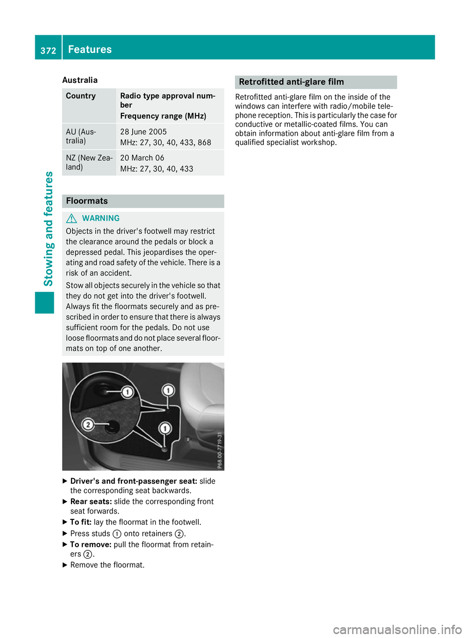
Driver's and front-passenger seat: slide
the corresponding seat backwards.
X Rear seats: slide the corresponding front
seat forwards.
X To fit: lay the floormat in the footwell.
X Press studs :onto retainers ;.
X To remove: pull the floormat from retain-
ers ;.
X Remove the floormat. Retrofitted anti-glare film
Retrofitted anti-glare film on the inside of the
windows can interfere with radio/mobile tele-
phone reception. This is particularly the case for conductive or metallic-coated films. You can
obtain information about anti-glare film from a
qualified specialist workshop. 372
FeaturesStowing and featu
res
Page 381 of 453
Depending on the operating conditions of the
vehicle, the remaining time or distance until the
next service due date is displayed.
The letter indicates which service is due. A A
stands for a minor service and B
B for a major ser-
vice. A number or another letter may be dis-
played after the letter.
Only for certain countries: the position after the
letter A
A or B Bindicates any necessary additional
maintenance work to be performed. If you notify a qualified specialist workshop of this display,
you will receive a statement on the associated
costs.
The ASSYST PLUS service interval display does
not take into account any periods of time during which the battery is disconnected.
Maintaining the time-dependent service sched-
ule:
X Note down the service due date displayed in
the multifunction display before disconnect-
ing the battery.
or X After reconnecting the battery, subtract the
battery disconnection periods from the ser-
vice date shown on the display. Hiding service messages
X Press the %ora button on the steering
wheel. Displaying service messages
X Switch the ignition on.
X Press the =or; button on the steering
wheel to select the Serv. Serv.menu.
X Press the 9or: button to select the
ASSYST
ASSYST PLUS
PLUSsubmenu and confirm by press-
ing the abutton.
The service due date appears in the multi-
function display. Information about Service
Resetting the ASSYST PLUS service
interval display !
If the ASSYST PLUS service interval display
has been inadvertently reset, this setting can be corrected at a qualified specialist work-
shop.
Have service work carried out as described in the Service Booklet. This may otherwise lead
to increased wear and damage to the major
assemblies or the vehicle.
A qualified specialist workshop, e.g. a
Mercedes-Benz Dealership, will reset the
ASSYST PLUS service interval display after the
service work has been carried out. You can also
obtain further information on maintenance
work, for example.
Special service requirements The prescribed service interval is based on nor-
mal operation of the vehicle. Service work will
need to be performed more often if the vehicle is
operated under arduous conditions or increased loads, for example:
R regular city driving with frequent intermediate
stops
R if the vehicle is primarily used to travel short
distances
R for frequent operation in mountainous terrain
or on poor road surfaces
R if the engine is often left idling for long periods
In these or similar operating conditions, have,
for example, the air filter, engine oil and oil filter changed more frequently. The tyres must be
checked more frequently if the vehicle is oper-
ated under increased loads. Further informationcan be obtained at a qualified specialist work-
shop, e.g. a Mercedes-Benz Service Centre.
Driving abroad An extensive Mercedes-Benz Service network is
also available in other countries. You can obtain further information from any Mercedes-Benz
Service Centre. Care
General notes
H
Environmental note
Dispose of empty packaging and cleaning
cloths in an environmentally responsible man-
ner. 378
CareMaintenance and care
Page 386 of 453
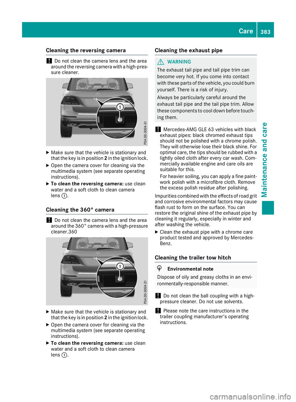
Cleaning the reversing camera
!
Do not clean the camera lens and the area
around the reversing camera with a high-pres-
sure cleaner. X
Make sure that the vehicle is stationary and
that the key is in position 2in the ignition lock.
X Open the camera cover for cleaning via the
multimedia system (see separate operating
instructions).
X To clean the reversing camera: use clean
water and a soft cloth to clean camera
lens :.
Cleaning the 360° camera !
Do not clean the camera lens and the area
around the 360° camera with a high-pressure cleaner.360 X
Make sure that the vehicle is stationary and
that the key is in position 2in the ignition lock.
X Open the camera cover for cleaning via the
multimedia system (see separate operating
instructions).
X To clean the reversing camera: use clean
water and a soft cloth to clean camera
lens :. Cleaning the exhaust pipe G
WARNING
The exhaust tail pipe and tail pipe trim can
become very hot. If you come into contact
with these parts of the vehicle, you could burn
yourself. There is a risk of injury.
Always be particularly careful around the
exhaust tail pipe and the tail pipe trim. Allow
these components to cool down before touch-
ing them.
! Mercedes-AMG GLE 63 vehicles with black
exhaust pipes: black chromed exhaust tips
should not be polished with a chrome polish. They will otherwise lose their black shine. For
optimal care, the tips should be rubbed with a lightly oiled cloth after every car wash. Com-
mercially available engine and care oils are
suitable for this.
For heavier soiling, you can apply a fine paint-
work polish with a microfibre cloth. Remove
the excess polish residue after polishing.
Impurities combined with the effects of road grit
and corrosive environmental factors may cause
flash rust to form on the surface. You can
restore the original shine of the exhaust pipe by cleaning it regularly, especially in winter and
after washing the vehicle.
X Clean the exhaust pipe with a chrome care
product tested and approved by Mercedes-
Benz.
Cleaning the trailer tow hitch H
Environmental note
Dispose of oily and greasy cloths in an envi-
ronmentally-responsible manner.
! Do not clean the ball coupling with a high-
pressure cleaner. Do not use solvents.
! Please note the care instructions in the
trailer coupling manufacturer's operating
instructions. Care
383Maintenance and care Z