2015 MERCEDES-BENZ GLE SUV ESP
[x] Cancel search: ESPPage 272 of 453
Driving on the motorway
When driving on a motorway, switching off the
combustion engine has a particularly positive
effect on fuel consumption and emissions.
If the driver removes his/her foot from the
accelerator pedal in the Comfortdrive program
and a speed of 130 km/h is not exceeded, the
combustion engine is automatically switched
off.
Further information on the automatic engine
switch-off (Y page 269).
ECO start/stop function General notes
The ECO start/stop function switches the com-
bustion engine off automatically when the vehi-
cle stops moving and at speeds below
130 km/h (Y page 269).
All vehicle systems remain active, e.g. the auto-
matic climate control.
The ECO start/stop function is neither available
in the Sport drive program nor during manual
shifting.
Automatic engine switch-off
The internal combustion engine is switched off
automatically if:
R the driver removes his/her foot from the
accelerator in the Comfortdrive program and
a speed of 130 km/h is not exceeded
(Y page 269)
R the internal combustion engine has reached
its operating temperature
R the driver only slightly depresses the accel-
erator pedal in order to, for example, maintain the current speed for a limited distance
R the bonnet is closed and engaged properly
R the high-voltage battery is charged suffi-
ciently
R no malfunctions are present in the hybrid
drive system
The internal combustion engine will not be
switched off automatically, if:
R the self-diagnosis function of the engine man-
agement is active
R there is a malfunction in the hybrid drive sys-
tem R
the climate control of the vehicle requires it
R the high-voltage battery is charging
(Y page 264).
Automatic engine start
The internal combustion engine, which has been automatically switched-off, starts automatically
in certain situations, when:
R the power demand from the driver via the
accelerator pedal is greater than the electric
motor alone can provide
R the driver switches to the Sportdrive pro-
gram or to manual gearshifting
R the charge level of the high-voltage battery
has reached the lower limit
R the driver has selected the CHARGE operating
mode
Overrun mode
In overrun mode, the combustion engine is
switched off and is disconnected from the drive
train. The electric motor:
R generates low thrust, which corresponds to
the overrun mode of an active combustion
engine
R functions as an alternator and produces the
necessary energy for the auxiliary consumers
and charges the high-voltage battery
Overrun mode is available in the Comfortdrive
program at speeds below 130 km/h.
Route-based operating strategy For the route-based operating strategy, the sys-
tem factors in information about the expected
route when route guidance is active.
The information on the route is provided by the
multimedia system and includes the following:
R road categories
R speed limitations
The use of electric energy is automatically opti- mally distributed from the beginning to the end
of the journey, using information about the
route. The distribution is pre-emptive and takes
into consideration:
R the sections of the journey ahead
R the energy consumption on the whole route Plug-in hybrid operation
269Driving and parking Z
Page 273 of 453
The charge status of the high-voltage battery is
thus systematically controlled. In addition, the
control function takes into account that:
R the fuel saving through the use of electrical
energy can vary, dependent on the route (e.g.
urban, interurban or motorway)
R the use of electrical energy is held available
for electric driving, particularly for urban
routes
The vehicle thus automatically selects the opti-
mum driving mode for the respective section of
the route.
The route-based operating strategy is available
under the following conditions:
R the Individual drive program is selected
R in the Individual drive program, the ECO set-
ting is selected under Drive
R HYBRID driving mode is selected
R active route guidance is activated
R suitable map data is available
When the route-based operating strategy is
being used, the area in front of the vehicle is
shown as green in the multifunction display. Parking
X Apply the electric parking brake.
The red !indicator lamp in the instrument
cluster lights up.
X Use the DIRECT SELECT lever to shift the
automatic transmission to P.
X Switch the ignition off.
The READY indicator in the instrument cluster
goes out.
Further information on parking and switching off the internal combustion engine (Y page 191).270
Plug-in hybrid operationDriving and parking
Page 276 of 453
To avoid hazardous situations:
R make sure to check the noseweight before
each journey
R use a drawbar noseweight as close as possi-
ble to the maximum noseweight
R do not exceed the maximum permissible
noseweight
R do not use a noseweight lower than the min-
imum noseweight
When reversing the vehicle towards the trailer,
make sure there is nobody between the trailer
and the vehicle.
Couple and uncouple the trailer carefully. If you do not couple the trailer to the towing vehicle
correctly, the trailer could become detached.
Make sure that the following values are not
exceeded:
R the permissible trailer drawbar noseweight
R the permissible trailer load
R the permissible rear axle load of the towing
vehicle
R the maximum permissible gross vehicle
weight of both the towing vehicle and the
trailer
The applicable permissible values, which must
not be exceeded, can be found:
R in your vehicle documents
R on the identification plates of the trailer tow
hitch and the trailer
R on the vehicle identification plate
If the values differ, the lowest value applies.
You will find the values approved by the manu-
facturer on the vehicle identification plates and
those for the towing vehicle under "Technical
data" (Y page 447).
When towing a trailer, your vehicle's handling
characteristics will be different in comparison to
when driving without a trailer.
The vehicle/trailer combination:
R is heavier
R is restricted in its acceleration and gradient-
climbing capability
R has an increased braking distance
R is affected more by strong crosswinds
R demands more sensitive steering
R has a larger turning circle
This can impair the vehicle's handling charac-
teristics. Adapt your driving style accordingly.
Maintain a safe distance. Drive carefully. When towing a trailer, always adjust your speed
to the current road and weather conditions. Do
not exceed the maximum permissible speed for
your vehicle/trailer combination. Notes on towing a trailer
General notes Check the tyre pressures when towing a trailer.
You will find the values in the tyre pressure table in the vehicle fuel filler flap (Y page 408).
Please note that when towing a trailer, the fol-
lowing driving systems have limited availability
or are not available at all.
R PARKTRONIC (Y page 225)
R Blind Spot Assist (Y page 244)
R Active Lane Keeping Assist (Y page 250)
R Active Parking Assist (Y page 228)
On vehicles without level control, the height of
the ball coupling will alter according to the load
placed on the vehicle. If necessary, use a trailer with a height-adjustable drawbar.
You will find fitting dimensions and loads under
"Technical data" (Y page 446).
Driving tips Observe the information on ESP
®
trailer stabili-
sation (Y page 77) and on pulling away with a
trailer (Y page 161).
Select the Comfortdrive program using the
DYNAMIC SELECT controller (Y page 166).
The maximum permissible speed for vehicle/
trailer combinations depends on the type of
trailer. Before beginning the journey, check the
trailer's documents to see what the maximum
permitted speed is. Observe the legally prescri-
bed maximum speed in the relevant country.
For certain Mercedes-Benz vehicles, the maxi-
mum permissible rear axle load is increased
when towing a trailer. See the "Technical data"
section to find out whether this applies to your
vehicle (Y page 447). If you utilise any of the
added maximum rear axle load when towing a
trailer, the vehicle/trailer combination may not
exceed a maximum speed of 100 km/hf or rea-
sons concerning the operating permit. This also
applies in countries in which the permissible
maximum speed for vehicle/trailer combina-
tions is above 100 km/h. Towing a trailer
273Driving and parking Z
Page 279 of 453
X
Check that the trailer lighting system is work-
ing.
X Push the combination switch upwards and
downwards and check whether the corre-
sponding turn signal on the trailer is flashing.
A connected trailer is only detected when the
electrical connection is established correctly
and when the lighting system is working prop-
erly. The function of other systems also depends on this, for example:
R ESP ®
R PARKTRONIC
R Active Parking Assist
R Active Blind Spot Assist
R Active Lane Keeping Assist
i Vehicles with the AIRMATIC package:
if
you couple up a trailer, the vehicle initially
remains at the selected level of the drive pro- gram set. Observe the following when cou-
pling up a trailer:
R If the normal level was not selected previ-
ously, the vehicle automatically adopts the
normal level starting from a speed of
30 km/h. Even at higher speeds, it does not drop below the normal level.
R Vehicle levels below the normal level are
not available.
R The raised level is available up to a speed of
30 km/h.
R This also applies when using accessories
that are plugged into the socket of the
trailer tow hitch (e.g. a bicycle rack).
R Before driving with a trailer, please observe
the information on the trailer support
wheel. Uncoupling a trailer
Important safety notes G
WARNING
If you uncouple a trailer with an engaged over- run brake, you could trap your hand between
the vehicle and the trailer drawbar. This poses a risk of injury.
Do not uncouple a trailer with an engaged
overrun brake. G
WARNING
Vehicles with level control:
If you disconnect the trailer cable, the vehicle is lowered. This can cause you or others to
become trapped between the vehicle body
and tyres, or underneath the vehicle. This
poses a risk of injury.
Make sure that no-one is in the immediate
vicinity of the wheel arch or underneath the
vehicle when disconnecting the trailer cable.
! Do not disconnect a trailer with an engaged
overrun brake. Otherwise, your vehicle could
be damaged by the rebounding of the overrun
brake.
! Remove the adapter cable before folding in
the ball coupling. You could otherwise dam-
age the rear bumper and the adapter cable.
Steel-sprung vehicles X
Shift the transmission to position P.
X Apply the electric parking brake.
X Secure the trailer against rolling away.
X Remove the trailer cable and decouple the
trailer.
Vehicles with the AIRMATIC package X
Shift the transmission to position P.
X Apply the electric parking brake.
X Start the engine.
X Close the doors and tailgate.
X Secure the trailer against rolling away.
X Remove the trailer cable and decouple the
trailer.
X Switch off the engine. Swinging the ball coupling in
! Do not attempt to speed the up the swing-
out procedure by applying additional pressure
with your foot. The system could otherwise be
mechanically damaged. 276
Towing a trailerDriving and parking
Page 281 of 453
The trailer battery may not be charged from
the power supply.
When it leaves the factory, your vehicle's trailer
socket is equipped with a permanent power
supply and a power supply that is switched on
via the ignition lock.
The permanent power supply is supplied via
trailer socket pin 9.
The power supply that is switched on via the
ignition lock is supplied via trailer socket pin 10.
The trailer's permanent power supply is
switched off in the event of low vehicle supply
voltage and after six hours at the latest.
You can find more information about fitting the
trailer electrics at a qualified specialist work-
shop.
X To switch the connected power supply on
or off: turn the key to position 2or 0respec-
tively (Y page 158). Failure check for LEDs
If LED lamps are fitted in the trailer, a malfunc-
tion message may appear in the multifunction
display even if there is no fault. The reason for
the error message may be that the current has
fallen below the minimum of 50 mA.
To ensure reliable indication of the failure, each LED chain in the trailer lighting must be guaran-
teed a minimum current of 50 mA. Trailer with 7-pin connector
General notes Trailer with 7-pin connector:
you can connect
to the 13-pin socket on the ball coupling using
an adapter or, if necessary, an adapter cable.
Both can be obtained at a qualified specialist
workshop.
Fitting the adapter !
Make sure that there is sufficient cable play
so that the cable cannot become detached
when cornering.
! Remove the adapter cable before folding in
the ball coupling. You could otherwise dam-
age the rear bumper and the adapter cable. X
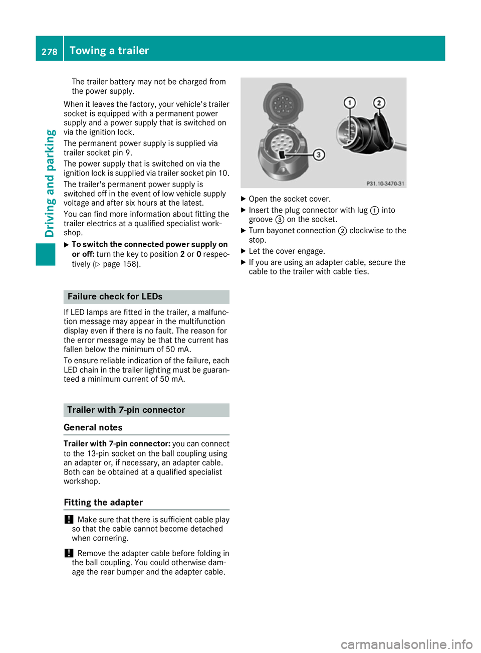
Open the socket cover.
X Insert the plug connector with lug :into
groove =on the socket.
X Turn bayonet connection ;clockwise to the
stop.
X Let the cover engage.
X If you are using an adapter cable, secure the
cable to the trailer with cable ties. 278
Towing a trailerDriving and parking
Page 298 of 453
X
Press the :or9 button to select the
Automatic door locks
Automatic door locks function.
When the Automatic
Automatic door
doorlocks
locks function is
activated, the vehicle doors are displayed in
orange in the multifunction display.
X Press the abutton to save the setting.
For further information on the automatic locking
feature; see (Y page 92).
Activating/deactivating the acoustic
locking confirmation
If you switch on the Acoustic
Acoustic Lock Lockfunction, an
acoustic signal sounds when you lock the vehi-
cle.
X Press the =or; button on the steering
wheel to select the Settings
Settings menu.
X Press the :or9 button to select the
Vehicle
Vehicle submenu.
X Press ato confirm.
X Press the :or9 button to select the
Acoustic Lock Acoustic Lock function.
If the Acoustic Lock
Acoustic Lock function is activated,
the & symbol in the multifunction display
lights up orange.
X Press the abutton to save the setting.
Heating submenu Auxiliary heating departure time
G
DANGER
If the exhaust pipe is blocked or sufficient
ventilation is not possible, toxic exhaust
fumes can enter the vehicle, especially car-
bon monoxide. This is the case, e.g. in
enclosed spaces, or if the vehicle is stuck in
snow. There is a risk of fatal injuries.
You should switch off the auxiliary heating in
enclosed spaces which do not have an extrac- tion system, e.g. a garage. If the vehicle is
stuck in snow and you must leave the auxiliary
heating running, keep the exhaust pipe and
the area around the vehicle clear of snow. To guarantee a sufficient supply of fresh air, open
a window on the side of the vehicle away from the wind. G
WARNING
When the auxiliary heating is switched on,
parts of the vehicle can become very hot.
Flammable materials such as leaves, grass or twigs may ignite if they come into contact
with:
R hot parts of the exhaust system
R the exhaust gas itself
There is a risk of fire.
When the auxiliary heating is switched on,
make sure that:
R no flammable materials come into contact
with hot vehicle components
R the exhaust gas can escape from the
exhaust pipe unhindered
R the exhaust gas does not come into contact
with flammable materials.
! Operating the auxiliary heating/ventilation
draws on the vehicle battery. After you have
heated or ventilated the vehicle a maximum of two times, drive for a longer distance.
Only vehicles with auxiliary heating have this
function.
In the Heating Heating submenu, you can select a
stored departure time or change a departure
time.
The auxiliary heating timer function calculates
the switch-on time according to the outside
temperature so that the vehicle is preheated by the departure time. When the departure time isreached, the auxiliary heating continues to heat
for a further five minutes and then switches off. The auxiliary heating adopts the THERMATIC orTHERMOTRONIC temperature setting.
You can switch off the auxiliary heating by using
the remote control or the auxiliary heating but-
ton on the centre console.
i Switch the auxiliary heating on regularly
once a month for about ten minutes.
Further information on auxiliary heating
(Y page 149). Menus and submenus
295On-board computer and displays Z
Page 301 of 453
ture
?and Bare displayed in white in the
multifunction display.
If the multifunction display shows oil temper- ature ?orB in blue, the engine or the
transmission are not yet at normal operating
temperature. Avoid using the full output of the engine during this time.
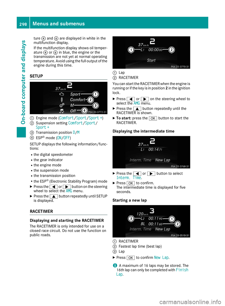
SETUP :
Engine mode (Comfort Comfort/Sport Sport/Sport +
Sport +)
; Suspension setting Comfort
Comfort/SportSport/
Sport +
Sport +
= Transmission position D
D/MM
? ESP ®
mode (ON ON/OFF
OFF )
SETUP displays the following information/func- tions:
R the digital speedometer
R the gear indicator
R the engine mode
R the suspension mode
R the transmission position
R the ESP ®
(Electronic Stability Program) mode
X Press the =or; button on the steering
wheel to select the AMG
AMG menu.
X Press the 9button repeatedly until SETUP
is displayed.
RACETIMER Displaying and starting the RACETIMER
The RACETIMER is only intended for use on a
closed race circuit. Do not use the function on
public roads. :
Lap
; RACETIMER
You can start the RACETIMER when the engine is running or if the key is in position 2in the ignition
lock.
X Press =or; on the steering wheel to
select the AMG
AMGmenu.
X Press the 9button repeatedly until the
RACETIMER is shown.
X To start: press the abutton to start the
RACETIMER.
Displaying the intermediate time X
Press the =or; button to select
Interm. Time
Interm. Time.
X Press ato confirm.
The intermediate time is displayed for five
seconds.
Starting a new lap :
RACETIMER
; Fastest lap time (best lap)
= Lap
X Press ato confirm New Lap
New Lap.
i A maximum of 16 laps may be stored. The
16th lap can only be completed with Finish
Finish
Lap
Lap . 298
Menus and submenusOn-board computer and displays
Page 303 of 453
Display messages
Introduction
General notes Display messages appear in the multifunction display.
Display messages with graphic symbols are simplified in the Owner's Manual and may differ from
the symbols in the multifunction display.
Please respond in accordance with the display messages and follow the additional notes in this
Owner's Manual.
Certain display messages are accompanied by an audible warning tone or a continuous tone.
When you stop and park the vehicle, please observe the notes on:
R HOLD function (Y page 219)
R Parking (Y page 191)
Hiding display messages X
Press the aor% button on the steering wheel.
The multifunction display fades the display message out.
High-priority display messages are shown by the multifunction display in red. Some high-priority
display messages cannot be hidden.
The multifunction display shows these messages continuously until the causes for the messages
have been remedied.
Message memory The on-board computer saves certain display messages in the
message memory. You can call up
the display messages:
X Press =or; on the steering wheel to select the Serv. Serv.menu.
If there are display messages, the multifunction display shows 2 messages
2 messages, for example.
X Press the 9or: button to select the entry, e.g. 2 messages
2 messages.
X Press ato confirm.
X Press the 9or: button to scroll through the display messages.
When the ignition is switched off, all display messages are deleted apart from some high-priority
display messages. Once the causes of the high-priority display messages have been rectified, these display messages are deleted as well. 300
Display
messagesOn-board computer and displays