2015 MERCEDES-BENZ GLC SUV engine
[x] Cancel search: enginePage 302 of 497
The internal combustion engine will not be
switched off automatically, if:
R the self-diagnosis function of the engine
control unit is still active
R there is a malfunction in the hybrid drive
system
R the climate control of the vehicle requires it
R the high-voltage battery is being charged
(Y page 292)
R automatic emissions tests are running
Automatic engine start
The internal combustion engine, which has
been automatically switched-off, starts auto-
matically in certain situations, when:
R the power demand from the driver via the
accelerator pedal is greater than the elec-
tric motor alone can provide
R the driver switches to drive program Sor M
R the charge level of the high-voltage battery
has reached the lower limit
R the settings of the automatic climate con-
trol require it, e.g. at external temperatures
above 30 †
Overrun mode
In overrun mode, the combustion engine is
switched off and is disconnected from the
drive train. The electric motor:
R generates low thrust, which corresponds to
the overrun mode of an active combustion
engine
R functions as an alternator and produces the
necessary energy for the auxiliary consum- ers and charges the high-voltage battery
Overrun mode is available in drive program E
below 160 km/h.
In drive program E, after the accelerator pedal
has been released the coasting characteris-
tics of the vehicle are adapted to the traffic
conditions. Further information about the
haptic accelerator pedal (Y page 297).Route-based energy management For route-based energy management, the
system factors in information about the
expected route when route guidance is
active.
The information on the route is provided by
COMAND Online and includes the following:
R road categories
R speed limitations
R data on downhill gradients
The use of electric energy is automatically
optimally distributed from the beginning to
the end of the journey, using information
about the route. The distribution is pre-emp-
tive and takes into consideration:
R the sections of the journey ahead
R the energy consumption on the whole route
The charge status of the high-voltage battery
is thus systematically controlled. In addition,
the control function takes into account that:
R the fuel savings through the use of electri-
cal energy can vary, depending on the route
(e.g. urban, interurban or motorway)
R the use of electrical energy is held available
in particular for electric operation (e.g.
urban routes)
The vehicle thus automatically selects the
optimum driving mode for the respective sec- tion of the route.
Route-based energy management is available
under the following conditions:
R drive program Eis selected
R HYBRID driving mode is selected
R active route guidance is activated
R suitable map data is available
When route-based energy management is in
operation, the area in front of the vehicle is
shown as green in the multifunction display. PLUG‑IN HYBRID operation
299Driving and parking Z
Page 303 of 497
Parking
X Apply the electric parking brake.
The red !indicator lamp in the instru-
ment cluster lights up.
X Use the DIRECT SELECT lever to shift the
automatic transmission to P.
X Switch the ignition off.
The READY indicator in the instrument clus-
ter goes out.
Further information on parking and switching off the internal combustion engine
(Y page 220). 300
PLUG‑IN HYBRID operationDriving and parking
Page 304 of 497
Problems with PLUG-IN HYBRID operation
Internal combustion engine Problem
Possible causes/consequences and
M
MSolutions You cannot start the
internal combustion
engine. The multifunc-
tion display shows no
display messages. The
READY indicator in the
multifunction display is
off. For example, self-diagnosis is not yet complete or the hybrid drive
system is malfunctioning.
X Switch off the ignition and turn it back on.
X Try to start the internal combustion engine again.
If the internal combustion engine still does not start: X Consult a qualified specialist workshop. You wish to pull away,
but the ECO start/stop
function does not start
the internal combus-
tion engine. The READY
indicator in the multi-
function display is off. The ECO start/stop function has failed. The warning and indicator
lamps in the instrument cluster light up.
X Shift the transmission to P.
X Switch off the ignition and turn it back on.
X Start the engine. The hybrid drive system is malfunctioning.
X Consult a qualified specialist workshop. Recuperative Brake System
Problem
Possible causes/consequences and
M MSolutions Braking resistance is
reduced and brake
pedal travel is longer
than usual.
G
Risk of accident
The Recuperative Brake System is malfunctioning.
X Observe the additional display messages in the multifunction
display (Y page 335).
X Observe the information regarding indicator and warning lamps
in the instrument cluster (Y page 377) . PLUG‑IN HYBRID operation
301Driving and parking Z
Page 305 of 497
Hybrid drive system
Problem
Possible causes/consequences and
M
MSolutions The hybrid drive system
has been switched off
automatically. You have been in an accident.
The hybrid drive system remains switched off if:
R the internal combustion engine cannot be restarted after a few
seconds.
R the red 6restraint system warning lamp in the instrument
cluster is lit.
X Consult a qualified specialist workshop. The hybrid drive system
has been switched off
automatically. The mul-
tifunction display also
shows a display mes-
sage. An electrical short circuit has occurred in the hybrid drive system
or an electrical connection has been disconnected.
X Observe the additional display messages in the multifunction
display (Y page 335).
X Consult a qualified specialist workshop. Towing a trailer
Important safety notes
G
WARNING
You could lose control of the vehicle/trailer
combination if it begins to swerve. The vehi-
cle/trailer combination could even overturn.
There is a risk of an accident.
On no account should you attempt to
straighten out the vehicle/trailer combina-
tion by increasing speed. Decrease your
speed and do not countersteer. Brake if nec-
essary. G
WARNING
If the maximum the permissible load for a car- rier system is exceeded, the carrier could
come loose from the vehicle and endanger
other road users. There is a risk of an accident and injury.
Never exceed the permissible noseweight
when using a carrier. Exceeding the maximum permissible nose-
weight of the trailer drawbar on the ball cou-
pling may cause damage to the following:
R your vehicle
R the trailer
R the ball coupling
R trailer tow hitch
The vehicle/trailer combination could
become unstable.
If the noseweight used is lower than the min- imum permissible noseweight, the vehicle/
trailer combination could also become unsta- ble.
To avoid hazardous situations:
R make sure to check the noseweight before
each journey
R use a drawbar noseweight as close as pos-
sible to the maximum noseweight
R do not exceed the maximum permissible
noseweight
R do not use a noseweight lower than the
minimum noseweight 302
Towing a trailerDriving and parking
Page 307 of 497
of the added maximum rear axle load when
towing a trailer, the vehicle/trailer combina-
tion may not exceed a maximum speed of
100 km/h for reasons concerning the oper-
ating permit. This also applies in countries in
which the permissible maximum speed for
vehicle/trailer combinations is above
100 km/h.
When towing a trailer, your vehicle's handling characteristics will be different in comparison
to when driving without a trailer and it will
consume more fuel.
Change into a lower gear in good time on long
and steep downhill gradients.
This also applies if cruise control, DISTRONIC PLUS or SPEEDTRONIC are activated.
This will use the braking effect of the engine,
so less braking will be required to maintain
vehicle speed. This relieves the load on the
brake system and prevents the brakes from
overheating and wearing too quickly. If you
need additional braking, depress the brake
pedal repeatedly rather than continuously.
Driving tips If the trailer swings from side to side:
X Do not accelerate.
X Do not countersteer.
X Brake if necessary.
R Maintain a greater distance to the vehicle in
front than when driving without a trailer.
R Avoid braking abruptly. If possible, brake
gently at first to allow the trailer to run on.
Then, increase the braking force rapidly.
R The values given for gradient-climbing
capabilities from a standstill refer to sea
level. When driving in mountainous areas,
note that the power output of the engine,
and consequently the vehicle's gradient-
climbing capability, decrease with increas-
ing altitude. Swinging out the ball coupling
G
WARNING
If the ball coupling is not engaged, the trailer
may come loose. There is a risk of an accident.
Make sure that the ball coupling is securely
engaged and locked in position.
! Do not attempt to speed the up the swing-
out procedure by applying additional pres-
sure with your foot. The system could oth-
erwise be mechanically damaged.
In order to tow a trailer with your vehicle, you
must swing out the ball coupling using the
switch in the driver's door or in the tailgate.
The trailer power socket is integrated in the
ball coupling and swivels out with it.
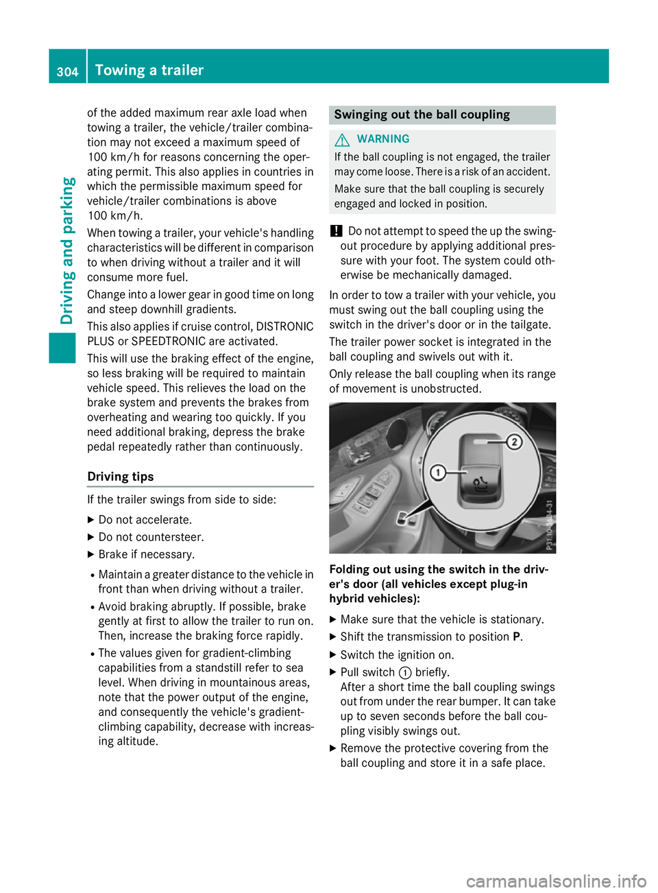
Only release the ball coupling when its range of movement is unobstructed. Folding out using the switch in the driv-
er's door (all vehicles except plug-in
hybrid vehicles):
X Make sure that the vehicle is stationary.
X Shift the transmission to position P.
X Switch the ignition on.
X Pull switch :briefly.
After a short time the ball coupling swings
out from under the rear bumper. It can take
up to seven seconds before the ball cou-
pling visibly swings out.
X Remove the protective covering from the
ball coupling and store it in a safe place. 304
Towing a trailerDriving and parking
Page 312 of 497
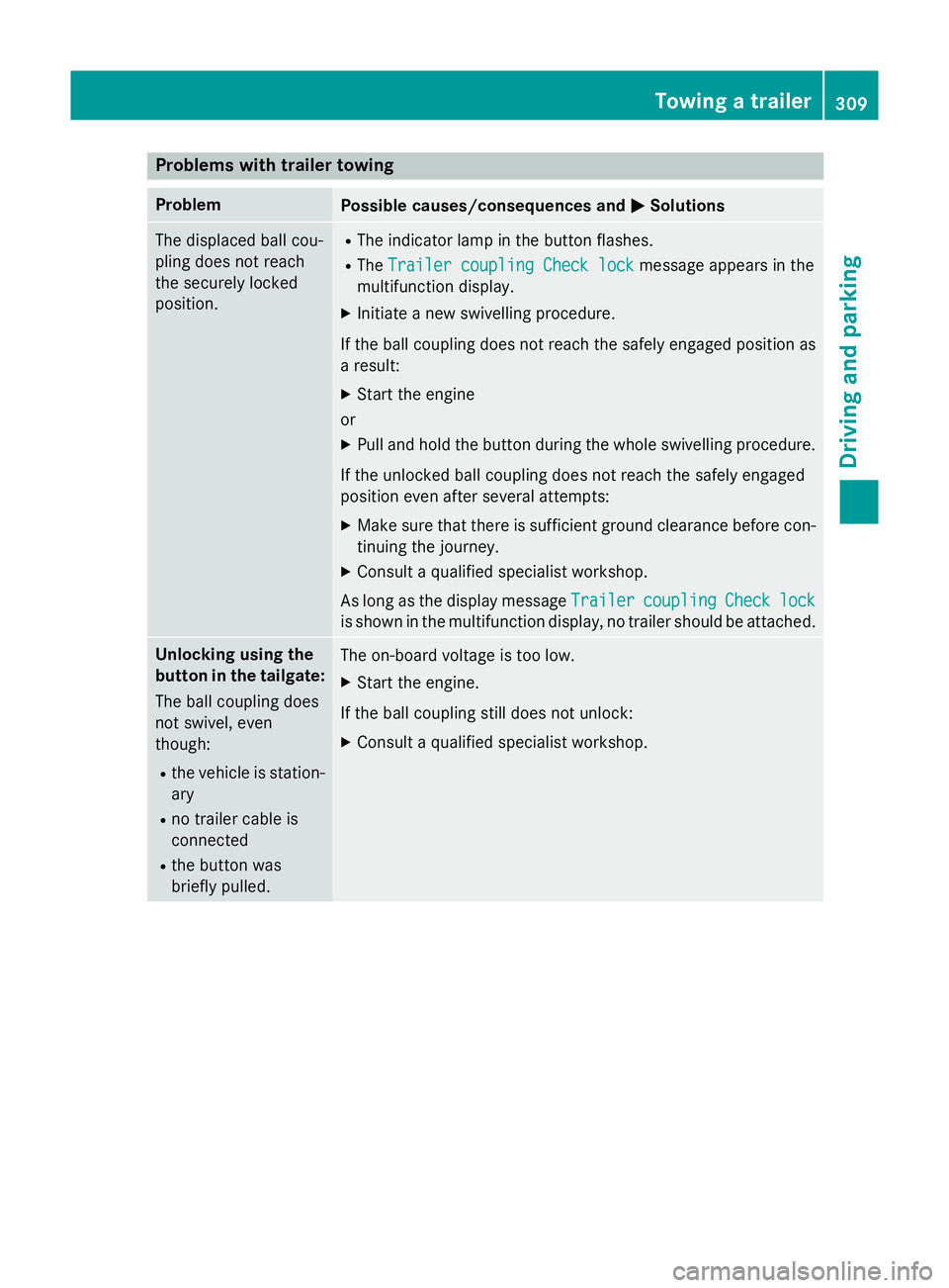
Problems with trailer towing
Problem
Possible causes/consequences and
M
MSolutions The displaced ball cou-
pling does not reach
the securely locked
position. R
The indicator lamp in the button flashes.
R The Trailer coupling Check lock Trailer coupling Check lock message appears in the
multifunction display.
X Initiate a new swivelling procedure.
If the ball coupling does not reach the safely engaged position as
a result:
X Start the engine
or
X Pull and hold the button during the whole swivelling procedure.
If the unlocked ball coupling does not reach the safely engaged
position even after several attempts:
X Make sure that there is sufficient ground clearance before con-
tinuing the journey.
X Consult a qualified specialist workshop.
As long as the display message Trailer
Trailercoupling
coupling Check
Checklock
lock
is shown in the multifunction display, no trailer should be attached. Unlocking using the
button in the tailgate:
The ball coupling does
not swivel, even
though:
R the vehicle is station-
ary
R no trailer cable is
connected
R the button was
briefly pulled. The on-board voltage is too low.
X Start the engine.
If the ball coupling still does not unlock:
X Consult a qualified specialist workshop. Towing a trailer
309Driving and parking Z
Page 313 of 497
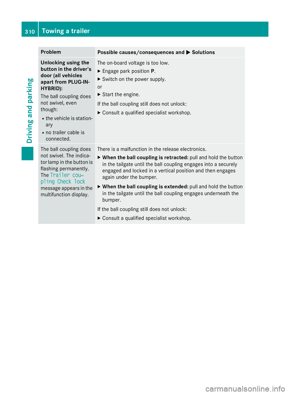
Problem
Possible causes/consequences and
M
MSolutions Unlocking using the
button in the driver's door (all vehicles
apart from PLUG-IN-
HYBRID):
The ball coupling does
not swivel, even
though:
R the vehicle is station-
ary
R no trailer cable is
connected. The on-board voltage is too low.
X Engage park position P.
X Switch on the power supply.
or
X Start the engine.
If the ball coupling still does not unlock:
X Consult a qualified specialist workshop. The ball coupling does
not swivel. The indica-
tor lamp in the button is flashing permanently.
The Trailer cou‐ Trailer cou‐
pling Check lock
pling Check lock
message appears in the
multifunction display. There is a malfunction in the release electronics.
X When the ball coupling is retracted: pull and hold the button
in the tailgate until the ball coupling engages into a securely
engaged and locked in a vertical position and then engages
again under the bumper.
X When the ball coupling is extended: pull and hold the button
in the tailgate until the ball coupling engages underneath the
bumper.
If the ball coupling still does not unlock:
X Consult a qualified specialist workshop. 310
Towing a trailerDriving and parking
Page 316 of 497
brightness will depend upon the brightness
of the ambient light.
i The light sensor in the instrument cluster
automatically controls the brightness of
the multifunction display.
In daylight, the displays in the instrument
cluster are illuminated. A dimming function
is not possible in daylight. Speedometer with segments
The speedometer is divided into segments on vehicles with DISTRONIC PLUS.
The segments in the speedometer indicate
which speed range is available.
R Cruise control activated (Y page 230):
The segments light up from the stored
speed to the type-tested maximum speed.
R Variable SPEEDTRONIC activated
(Y page 233):
The segments light up from the start of the
scale to the selected limit speed.
R DISTRONIC PLUS activated (Y page 236):
One or two segments in the set speed
range light up.
R DISTRONIC PLUS detects a vehicle in front
moving more slowly than the stored speed:
The segments between the speed of the
vehicle in front and the stored speed light
up. Rev counter
! Do not drive in the overrevving range.
Doing so will damage the engine.
The red band in the rev counter indicates the
engine's overrevving range.
The fuel supply is interrupted to protect the
engine when the red band is reached.
PLUG-IN HYBRID vehicles: when you select
the E-MODE operating mode, the display in
the instrument cluster switches from rev
counter to wattmeter (Y page 289). Outside temperature display
You should pay special attention to road con-
ditions when temperatures are around freez-
ing point.
Bear in mind that the outside temperature
display indicates the measured air tempera-
ture and not the road surface temperature.
The outside temperature display is in the mul- tifunction display (Y page 315).
Changes in the outside temperature are dis-
played after a short delay. Coolant temperature gauge
G
WARNING
If you open the bonnet while the engine is
overheating or while there is a fire in the
engine compartment, you could come into
contact with hot gases or other leaking ser-
vice products. There is a danger of injury.
Allow an overheating engine to cool down
before opening the bonnet. If there is a fire in the engine compartment, leave the bonnet
closed and notify the fire brigade.
All vehicles except PLUG-IN HYBRID vehicles: the coolant temperature gauge is in the lower
section of the rev counter (Y page 34).
PLUG-IN HYBRID vehicles: the multifunction
display shows the coolant temperature in the
Coolant Coolant submenu (Y page 327).
At high outside temperatures and when driv-
ing uphill, the coolant temperature may rise
to the end of the scale.
Under normal operating conditions and with
the specified coolant level, the coolant tem-
perature may rise to 120 †. Displays and operation
313On-board computer and displays Z