2015 MERCEDES-BENZ G-CLASS SUV lock
[x] Cancel search: lockPage 21 of 274

Tow-startingEmergency engine starting ............ 225
Important safety notes .................. 222
Towing a trailer
7-pin connector ............................. 143
Axle load, permissibl e.................... 269
Bulb failure indicator for LED
lamps ............................................. 143
Cleaning the trailer tow hitch ......... 211
Coupling up a traile r...................... 141
Decoupling a trailer ....................... 142
Driving tips .................................... 137
Installing the ball coupling ............. 140
Lights display message .................. 148
Mounting dimensions .................... 268
Power supply ................................. 143
Trailer load s................................... 269
Trailer tow hitch ............................. 268
Towing away
Important safety guidelines ........... 222
In the event of malfunctions .......... 224
With both axles on the ground ....... 223
Towing eye
Front .............................................. 223
Rear ............................................... 223
Traffic reports
see also Digital Operator's Man-
ual .................................................. 172
Trailer
Display message ............................ 148
Trailer coupling
see Towing a trailer
Trailer loads
Technical data ............................... 269
Trailer loads and drawbar nose-
weights ............................................... 142
Trailer tow hitch
Ball position ................................... 270
Trailer towing
ESP ®
................................................ 68
PARKTRONIC ................................. 130
Permissible trailer loads and
drawbar noseweights ..................... 142
Transfer case
General notes ................................ 132
Shift rang e..................................... 132
Shifting .......................................... 132
Shifting (general notes) .................. 133 Shifting (important safety notes
)... 132
Shifting to neutral .......................... 134
Switching off the off-road gear
ratio ............................................... 133
Switching on the off-road gear
ratio ............................................... 133
Transmission
see Automatic transmission
Transmission positions .................... 107
Transporting the vehicle .................. 224
Traveling uphill
Brow of hill ..................................... 112
Driving downhill ............................. 112
Maximum gradient-climbing capa-
bility ............................................... 112
Trim pieces (cleaning instruc-
tions) .................................................. 212
Trip computer (on-board com-puter) .................................................. 147
Trip odometer
Calling up ....................................... 147
Turn signals
Display message ............................ 148
Switching on/of f.............................. 92
TWR (Tongue Weight Rating) (defi-
nition) ................................................. 250
Type identification plate
see Vehicle identification plate
U
UnlockingEmergency unlocking ....................... 75
From inside the vehicle (central
unlocking button) ............................. 75
V
Variable SPEEDTRONICFunction/note s............................. 115
Vehicle
Correct use ...................................... 28
Data acquisition ............................... 29
Display message .................... 148, 160
Equipment ....................................... 27
Limited Warranty ............................. 29
Loading .......................................... 238
Locking (in an emergency) ............... 75
Index19
Page 22 of 274

Locking (SmartKey) .......................... 72
Lowering ........................................ 253
Parking for a long period ................ 112
Pulling away................................... 104
Raising ........................................... 251
Securing from rolling away ............ 251
Tow-starting ................................... 222
Towing away .................................. 222
Transporting .................................. 224
Unlocking (in an emergency) ........... 75
Unlocking (SmartKey) ...................... 72
Vehicle data ................................... 266
Vehicle data ....................................... 266
Vehicle data (off-road driving)
Approach/departure angle ............ 267
Fording depth ................................ 267
Maximum gradient climbing abil-
ity .................................................. 268
Vehicle dimensions ........................... 266
Vehicle emergency locking ................ 75
Vehicle identification number
see VIN
Vehicle identification plate .............. 258
Vehicle tool kit .................................. 214
Ventilation
Setting the airflow ......................... 100
Video
see also Digital Operator's Man-
ual .................................................. 172
Video (DVD) ........................................ 147
VIN ...................................................... 258
Voice Control System
see Separate operating instructions
W
Warning and indicator lampsABS ................................................ 163
Brakes ........................................... 162
Coolant .......................................... 168
Cruise control ................................ 113
Distance warning ........................... 169
DISTRONIC PLUS ........................... 169 ESP ®
.............................................. 165
ESP ®
OFF ....................................... 166
LIM (DISTRONIC PLUS) .................. 119
LIM (variable SPEEDTRONIC) ......... 116
Overview .......................................... 34 PASSENGER AIR BAG OFF ............... 43
Restraint system ............................ 167
Seat belt ........................................ 161
Tire pressure monitor .................... 170
Warning triangle ................................ 214
Washer fluid
Display message ............................ 148
Wheel bolt tightening torque ........... 253
Wheels
Changing a whee l.......................... 250
Checking ........................................ 231
Cleaning ......................................... 211
Important safety notes .................. 230
Interchanging/changing ................ 250
Mounting a new whee l................... 253
Mounting a whee l.......................... 251
Overview ........................................ 230
Removing a whee l.......................... 253
Storing ........................................... 251
Technical data ............................... 254
Tightening torque ........................... 253
Wheel size/tire size ....................... 254
Window curtain air bag
Display message ............................ 153
Operation ......................................... 51
Windows
see Side windows
Windshield
Defrosting ...................................... 100
Windshield heating ........................... 100
Windshield washer fluid
see Windshield washer system
Windshield washer system
Adding washer fluid ....................... 208
Notes ............................................. 265
Windshield wipers
Problem (malfunction) ..................... 96
Rear window wipe r.......................... 95
Replacing the wiper blades .............. 96
Switching on/of f.............................. 95
Winter driving
Slippery road surfaces ................... 112
Snow chains .................................. 232
Winter operation
General notes ................................ 232
Winter tires
M+S tires ....................................... 232
20Index
Page 24 of 274

Introduction
In addition to the printed Operator's Manual,the vehicle document wallet also contains
further operating instructions, such as:
R Digital Operator's Manual on CD
R Maintenance Booklet
R Equipment-dependent supplements
The printed Operator's Manual provides infor-
mation on selected functions of your vehicle.
You can also access the Digital Operator's
Manual via COMAND. If you have further
questions that are not covered in the printed
Operator's Manual, please consult the Digital
Operator's Manual. The vehicle functions and
functions of COMAND are described in the
Digital Operator's Manual.
You can purchase a printed Operator's Man-
ual with the same contents as the Digital
Operator's Manual in an authorized
Mercedes-Benz Center.
iYou will not incur any costs when calling
up the Digital Operator's Manual. It works
without connecting to the Internet.
In the following sections you will find further
information about: R how to install the Digital Operator's Manual
on your COMAND ( Ypage 22)
R how to access and operate the Digital Oper-
ator's Manual
R various options for accessing the individual
topics covered by the Digital Operator's
Manual.
There are three options for accessing via the
basic menu of the Digital Operator's Manual:
R Visual search
R Keyword Search
R Contents
You can change the set language for the Dig- ital Operator's Manual under "Settings" in thebasic menu.
Installation
Check whether or not the Digital Operator's
Manual has already been installed. To do so,
call up the Digital Operator's Manual via
COMAND as follows:
X Using the COMAND controller, select the® symbol from the menu bar in the
COMAND display and press Wto confirm.
X Choose the "Operator's Manual" selection
card and press Wto confirm.
There are two possibilities:
1. The Digital Operator's Manual is instal-
led. The basic menu for the Digital Opera-
tor's Manual opens.
2. The Digital Operator's Manual is not
installed. The following message appears:
The Operator's Manual has not yet
been installed. Please insert the
correct disc.
If the Digital Operator's Manual has not yet
been installed, you have the option of instal-
ling it yourself. You will find the installation CD
required in the vehicle document wallet.
The duration of the installation process may
vary.
The installation process takes approximately
five minutes. This timespan only applies if you install the Digital Operator's Manual while the
vehicle is at a standstill and no other
COMAND functions are in use at the time. The
duration of the installation process may
increase accordingly if other COMAND func-
tions such as navigation or telephony are in
use at the time.
If you encounter any problems during instal-
lation, please contact your authorized
Mercedes-Benz Center.
X To install the Digital Operator's Manual:
stop the vehicle safely, paying attention to
road and traffic conditions.
X Turn the SmartKey to position 2in the igni-
tion lock.
X Switch on COMAND.
22Digital Operator's Manual
Page 34 of 274
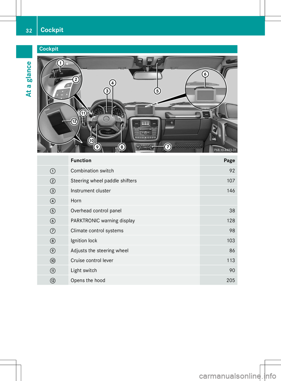
Cockpit
FunctionPage
:Combination switch92
;Steering wheel paddle shifters107
=Instrument cluster146
?Horn
AOverhead control panel38
BPARKTRONIC warning display128
CClimate control systems98
DIgnition lock103
EAdjusts the steering wheel86
FCruise control lever113
GLight switch90
HOpens the hood205
32Cockpit
At a glance
Page 41 of 274
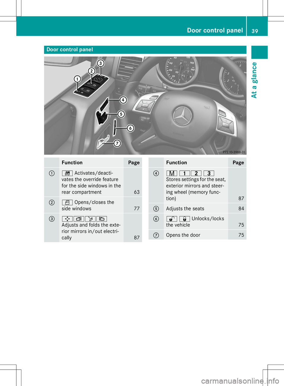
Door control panel
FunctionPage
:nActivates/deacti-
vates the override feature
for the side windows in the
rear compartment
63
;W Opens/closes the
side windows
77
=7 Zö\
Adjusts and folds the exte-
rior mirrors in/out electri-
cally
87
FunctionPage
?r 45 =
Stores settings for the seat, exterior mirrors and steer-
ing wheel (memory func-
tion)
87
AAdjusts the seats84
B%& Unlocks/locks
the vehicle
75
COpens the door75
Door control panel39
At a glance
Page 43 of 274
Useful information..............................42
Occupant safety .................................. 42
Children in the vehicle ........................55
Pets in the vehicle ............................... 64
Driving safety systems .......................64
Theft deterrent locking system .........68
41
Safety
Page 46 of 274
The seat belt system comprises:
R Seat belts
R Emergency Tensioning Devices for the
front seat belts and the outer seat belts in
the rear
R Seat belt force limiters
If the seat belt is pulled out at the belt sash
guide quickly or with a jerky movement, the
belt retractor locks. The belt strap cannot be
extracted any further.
The Emergency Tensioning Device tightens
the seat belt in an accident, pulling the belt
close against the body. However it does not
pull the vehicle occupant back in the direction of the backrest.
The Emergency Tensioning Device does not
correct an incorrect seat position or the rout-
ing of an incorrectly fastened seat belt.
When triggered, a seat belt force limiter helps
to reduce the force exerted by the seat belt on the vehicle occupant.
The seat belt force limiters for the front seats
are synchronized with the front air bags,
which absorb part of the deceleration force.
This can reduce the force exerted on the vehi-
cle occupants during an accident.
!If the front-passenger seat is unoccupied,
do not insert the belt tongue into the buckle of the front-passenger seat. This may oth-
erwise lead to the triggering of the Emer-
gency Tensioning Device in the event of an
accident, which will then need to bereplaced.
Important safety notes
The use of seat belts and child restraint sys-
tems is required by law in:
R all 50 states
R the U.S. territories
R the District of Columbia
R all Canadian provinces
Even where this is not required by law, all
vehicle occupants should correctly fasten
their seat belts before starting the journey.
GWARNING
If the seat belt is incorrectly fastened, it can-
not protect as intended. Furthermore, an
incorrectly fastened seat belt can cause addi- tional injury, for example, in an accident, dur-
ing braking or when abruptly changing direc-
tion. This poses an increased risk of injury or
even fatal injury.
Make sure that all vehicle occupants are
seated properly with a correctly fastened seat belt.
GWARNING
The seat belt does not offer the intended level of protection if you have not moved the back-
rest to an almost vertical position. When brak-
ing or in the event of an accident, you could
slide underneath the seat belt and sustain
abdomen or neck injuries, for example. This
poses an increased risk of injury or even fatal injury.
Adjust the seat properly before beginning
your journey. Always ensure that the backrest
is in an almost vertical position and that the
shoulder section of your seat belt is routed
across the center of your shoulder.
GWARNING
Persons under 5 ft (1.50 m) in height cannot
fasten the seat belt correctly without an addi- tional suitable restraint system. If the seat
belt is incorrectly fastened, it cannot protect
as intended. Furthermore, an incorrectly fas-
tened seat belt can cause additional injury, for
example, in an accident, during braking or an
abrupt change of direction. This poses an
increased risk of injury or even fatal injury.
For this reason, always secure persons under
5 ft (1.50 m) in height in suitable restraintsystems.
If a child younger than twelve years old and
under 5 ft (1.50 m) in height is traveling in the vehicle:
R always secure the child in a child restraint
system suitable for this Mercedes-Benz
44Occupant safety
Safety
Page 54 of 274
immediately replaced at a qualified specialistworkshop.
If Emergency Tensioning Devices are trig-
gered or air bags are deployed, you will hear a bang, and a small amount of powder may also
be released. The 6restraint system warn-
ing lamp lights up.
Only in rare cases will the bang affect your
hearing. The powder that is released gener-
ally does not constitute a health hazard, but it
may cause short-term breathing difficulties in
people with asthma or other respiratory prob-
lems. To avoid this, you may wish to get out of
the vehicle or open the windows as soon as it is safe to do so.
Air bags and pyrotechnic Emergency Tension-
ing Devices (ETDs) contain perchlorate mate- rial, which may require special handling and
regard for the environment. National guide-
lines must be observed during disposal. In
California, see www.dtsc.ca.gov/
HazardousWaste/Perchlorate/
index.cfm .
Method of operation
During the first stage of a collision, the
restraint system control unit evaluates impor-
tant physical data relating to vehicle deceler- ation or acceleration, such as:
R duration
R direction
R intensity
Based on the evaluation of this data, the
restraint system control unit triggers the
Emergency Tensioning Devices during a fron- tal or rear collision.
An Emergency Tensioning Device can only be
triggered, if:
R the ignition is switched on
R the components of the restraint system are
operational; see "Restraint system warning lamp" ( Ypage 42)
R the belt tongue is engaged in the buckle on
the respective front-passenger seat The Emergency Tensioning Devices in the
rear compartment are triggered independ-
ently of the lock status of the seat belts.
If the restraint system control unit detects a
more severe accident, further components of
the restraint system are activated independ-
ently of each other in certain frontal collision
situations:
R Driver's air bag
R Front-passenger front air bag
The front-passenger front air bag is activated or deactivated depending on the person on
the front-passenger seat. The front-
passenger front air bag can only deploy in an
accident if the PASSENGER AIR BAG OFF indi- cator lamp is off. Observe the information on
the PASSENGER AIR BAG OFF indicator lamp ( Y page 43).
Your vehicle has a two-stage driver's air bag.
During the first deployment stage the driver's air bag fills with sufficient propellant gas to
reduce the risk of injuries. The front air bag is
fully deployed with the maximum amount of
propellant gas if a second deployment thresh- old is reached within a few milliseconds.
The activation threshold of the Emergency
Tensioning Devices and the air bag are deter- mined by evaluating the rate of vehicle decel-
eration or acceleration which occurs at vari-
ous points in the vehicle. This process is pre-
emptive in nature. Deployment should take
place in good time at the start of the collision.
The rate of vehicle deceleration or accelera-
tion and the direction of the force are essen- tially determined by:
R the distribution of forces during the colli-sion
R the collision angle
R the deformation characteristics of the vehi-
cle
R the characteristics of the object with which
the vehicle has collided
Factors which can only be seen and measured after a collision has occurred do not play a
decisive role in the deployment of an air bag.
52Occupant safety
Safety