2015 MERCEDES-BENZ E-CLASS SALOON boot
[x] Cancel search: bootPage 254 of 497
X
Press the Øbutton in the centre con-
sole.
The vehicle menu appears.
X Select 360° camera
360° camera and press7to con-
firm.
The following appears depending on
whether transmission position Dor Ris
selected:
R as plit-screen with top view and the
image from the frontc amera or
R as plit-screen with top view and the
image from the reversin gcamera
Activating the 360° camera using
reverse gear You can show images from the 360° camera
automatically by engaging reverse gear.
X Make sure that the key is in position 2in the
ignition lock.
X Make sure that the ActivationbyR
Activatio nbyR
gear
gear function is selected in COMAND
Online/Audio 20 (see the separate
COMAND Online/Audio 20 operating
instructions).
X To show the 360° camera image: engage
reverse gear.
The area behind the vehicle is shown in the
COMAND/Audio 20 display in split-screen
mode. You see the top view of the vehicle
and the image from the reversin gcamera.
Selecting the split-screen and full
screen displays Switching between split screen views
X To switch to the line with the vehicle icons:
slide 5the controller.
X To select one of the vehicle icons: turn
3 the controller.
X To switch to 180° view
180° view: turn3 the
controller to select 180° view 180° viewand press
7 to confirm.
i The
180° view
180° view option is only availabl ein
the following views: R
Top view with image from the reversing
camera
R Top view with image from the frontc am-
era
Displays in the COMAND/Audio 20 dis-
play Important safety notes
The camera system may show
adistorted
view of obstacles or show them incorrectly or
not at all. Obstacles are not shown by the
system in the following locations:
R under the fronta nd rear bumpers
R very close to the fronta nd rear bumpers
R in the area immediately above the tailgate
handle/boot lid handle
R very close to the exterior mirrors
R in the transitional areas between the vari-
ous cameras in the virtual top view
! Objects not at ground level may appear to
be further away than they actually are, e.g.:
R the bumper of aparked vehicle
R the drawbar of atrailer
R the ball coupling of atrailer tow hitch
R the rear section of an HGV
R as lanted post
Use the guidelines only for orientation.
Approach object snofurther than the bot-
tom-most guideline. Driving systems
251Driving and parking Z
Page 272 of 497
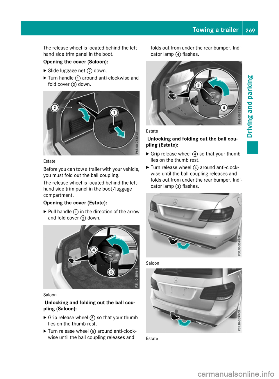
The release wheel is located behind the left-
hand side trim panel in the boot.
Opening the cover (Saloon):
X Slide luggage net ;down.
X Turn handle :around anti-clockwise and
fold cover =down. Estate
Before you can tow
atrailer with your vehicle,
you must fold out the ball coupling.
The release wheel is located behind the left-
hand side trim panel in the boot/luggage
compartment.
Opening the cover (Estate):
X Pull handle :in the direction of the arrow
and fold cover ;down. Saloon
Unlocking and folding out the ball cou-
pling (Saloon):
X Grip release wheel Aso that your thumb
lies on the thumb rest.
X Turn release wheel Aaround anti-clock-
wise until the ball coupling releases and folds out from under the rear bumper. Indi-
cator lamp ?flashes. Estate
Unlocking and folding out the ball cou-
pling (Estate):
X Grip release wheel ?so that your thumb
lies on the thumb rest.
X Turn release wheel ?around anti-clock-
wise until the ball coupling releases and
folds out from under the rear bumper. Indi- cator lamp =flashes. Saloon
Estate Towing
atrailer
269Driving and parking Z
Page 274 of 497
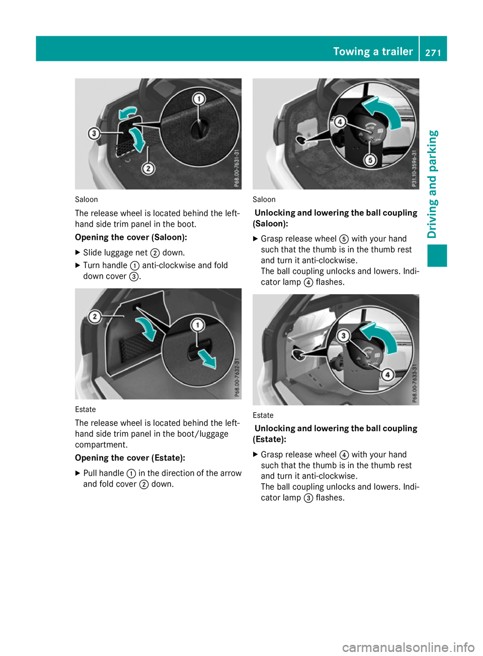
Saloon
The release wheel is located behind the left-
hand sid etrim panel in the boot.
Opening the cover (Saloon):
X Slide luggage net ;down.
X Turn handle :anti-clockwise and fold
dow ncover =. Estate
The release wheel is located behind the left-
hand sid etrim panel in the boot/luggage
compartment.
Opening the cover (Estate):
X Pull handle :in the direction of the arrow
and fol dcover ;down. Saloon
Unlockin gand lowering the bal lcou pling
(Saloon):
X Grasp release wheel Awith your hand
such that the thum bisinthe thum brest
and turn it anti-clockwise.
The ball coupling unlocks and lowers. Indi-
cator lamp ?flashes. Estate
Unlockin gand lowering the bal lcou pling
(Estate):
X Grasp release wheel ?with your hand
such that the thum bisinthe thum brest
and turn it anti-clockwise.
The ball coupling unlocks and lowers. Indi-
cator lamp =flashes. Towin
gatrailer
271Drivingand parking Z
Page 295 of 497
X
Press the :or9 button to set the
colour to SOLAR SOLAR,NEUTRAL NEUTRAL orPOLAR
POLAR.
X Press the aor% button to save the
setting.
Activating/deactivating the surround
lighting and exterior lighting delayed
switch-off
X Press the =or; button on the steer-
ing wheel to select the Settings
Settings menu.
X Press the :or9 button to select the
Light Light submenu.
X Press ato confirm.
X Press the :or9 button to select the
Surround lighting
Surround lighting function.
If the Surround
Surround lighting
lightingfunction is acti-
vated, the light cone and the area around
the vehicle are displayed in orange in the
multifunction display.
X Press the abutton to save the setting.
Deactivating delayed switch-off of the exte-
rior lighting temporarily:
X Before leaving the vehicle, turn the key to
position 0in the ignition lock.
X Turn the key to position 2in the ignition
lock.
The exterior lighting delayed switch-off is
deactivated.
Delayed switch-off of the exterior lighting is
reactivated the next time you start the
engine.
If you have activated the Surround light‐
Surround light‐
ing
ing function and the light switch is set to
Ã,t he following functions are activated
when it is dark:
R surround lighting: the exterior lighting
remains lit for 40 seconds after unlocking
with the key. If you start the engine, the
surround lighting is switched off and auto-
matic headlamp mode is activated
(Y page 143).
R exterior lighting delayed switch-off: the
exterior lighting remains lit for 60 seconds
after the engine is switched off. If you close all the doors and the boot lid/tailgate, the
exterior lighting goes off after 15 seconds.
i Dependin
gonyour vehicle's equipment,
when the surround lighting and delayed
switch-off exterior lighting are on, the fol-
lowing light up:
R Side lamps
R Surround lighting in the exterior mirrors
Activating/deactivating the interior light-
ing delayed switch-off
If you activat ethe Light. delay Switch Light. delay Switch
off
off function, the interior lighting remains on
for 20 seconds after you remove the key from the ignition lock.
X Press the =or; button on the steer-
ing wheel to select the Settings
Settings menu.
X Press the :or9 button to select the
Light
Light submenu.
X Press ato confirm.
X Press the :or9 button to select the
Light. delay
Light. delay function.
If the Light. delay
Light. delay function has been
switched on, the vehicle interior is dis-
played in orange in the multifunction dis-
play.
X Press the abutton to save the setting.
Vehicle Setting permanent SPEEDTRONIC
X Press the =or; button on the steer-
ing wheel to select the Settings Settingsmenu.
X Press the :or9 button to select the
Vehicle
Vehicle submenu.
X Press ato confirm.
X Press :or9 to select the Limit
Limit
speed (winter tyres):
speed (winter tyres): function.
You will see the curren tsetting.
X Press ato confirm.
X Press the :or9 button to adjust
permanen tSPEEDTRONIC in increment sof
ten (240 km/h 240 km/h to160 km/h
160 km/h). The Off
Offset- 292
Menus and submenusOn-board computer and displays
Page 345 of 497
Useful information
i This Owner's Manual describes all mod-
els, series and optional equipment for your
vehicle that were available at the time of
going to press. National variation sare pos-
sible. Not ethat your vehicle may not be
equipped with all of the function sdescri-
bed. This is also the case for system sand
function srelevan ttosafety.
i Read the information on qualified special-
ist workshops: (Y page 27). Stowage areas
Loading guidelines
G
WARNING
If objects, luggage or loads are not secured or not secured sufficiently, they could slip, tip
over or be flung around and thereby hit vehicle
occupants .There is arisk of injury, especially
when brakin gorabruptly changing directions.
Always stor eobjects so that they cannot be
flung around. Secure objects, luggage or
loads against slipping or tippin gbefore the
journey. G
WARNING
Combustion engines emit poisonous exhaust
gases such as carbon monoxide. Exhaust
gases can enter the vehicle interior if the boot
lid/tailgat eisopen when the engin eisrun-
ning, especially if the vehicle is in motion.
There is arisk of poisoning.
Always switc hoff the engin ebefore opening
the boot lid/tailgate. Never drive with the
boot lid/tailgat eopen. G
WARNING
The exhaust tail pipe and tail pipe trim can
becom every hot. If you come int ocontact
with thes eparts of the vehicle, you could burn
yourself. There is arisk of injury. Always be particularly careful around the
exhaust tail pipe and the tail pipe trim .Allow
thes ecomponents to cool down before touch-
ing them.
The handling characteristic sofaladen vehi-
cle are dependen tonthe distribution of the
load within the vehicle. For this reason ,you
should observ ethe following notes when
transporting aload:
R neve rexceed the maximum permissible
gross vehicle weight or the permissible axle loads for the vehicle (includin goccupants).
R the boot/luggage compartment is the pre-
ferred place to stor eobjects.
R position heavy loads as far forwards as pos-
sible and as low down in the boot/luggagecompartment as possible.
R the load must not protrude above the upper
edge of the seat backrests.
R always place the load against the rear or
fron tseat backrests .Make sure that the
seat backrests are securely locked into
place.
R always place the load behind unoccupied
seats if possible.
R use the lashing eyelets and the luggage
net stot ransport loads and luggage.
R only use lashing eyelets and fastenin gcom-
ponents that are suitable for the weight and size of the load.
R when transporting objects in the luggage
compartment,t he combined luggage cover
and net must always be installed (luggage
compartment cove rand safet ynet).
R secure the load with sufficiently strong and
wear-resistan tlashing material. Pad sharp
edges for protection.
i Load restraint
sare available at any quali-
fied specialist workshop, e.g. aMercedes-
Ben zService Centre. 342
Stowage areasStowing and features
Page 346 of 497
Stowage compartments
Important safety notes G
WARNING
If objectsint he passenger compartmen tare
stowed incorrectly, they can slide or be
thrown around and hit vehicle occupants.
There is arisk of injury, particularly in the
event of sudden braking or asudden change
in direction.
R Always stow objectssot hat they cannot be
thrown around in such situations.
R Always make sure that objectsdon ot pro-
trude from stowage spaces, luggage nets or stowage nets.
R Close the lockable stowage spaces while
driving.
R Always stow and secure heavy, hard, poin-
ted, sharp-edged, fragile or bulky objectsin
the boot/luggage compartment.
Observe the loading guidelines (Y page 342).
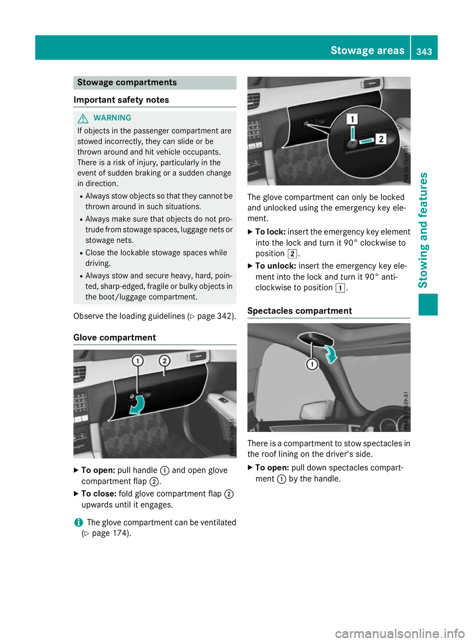
Glove compartment X
To open: pull handle :and open glove
compartmen tflap ;.
X To close: fold glove compartmen tflap ;
upwards until it engages.
i The glove compartmen
tcan be ventilated
(Y page 174). The glove compartmen
tcan only be locked
and unlocked using the emergency key ele-
ment.
X To lock: insert the emergency key element
into the lock and turn it 90° clockwise to
position 2.
X To unlock: insert the emergency key ele-
ment into the lock and turn it 90° anti-
clockwise to position 1.
Spectacles compartment There is
acompartmen ttostow spectacles in
the roof lining on the driver's side.
X To open: pull down spectacles compart-
ment :by the handle. Stowage areas
343Stowing and features Z
Page 348 of 497
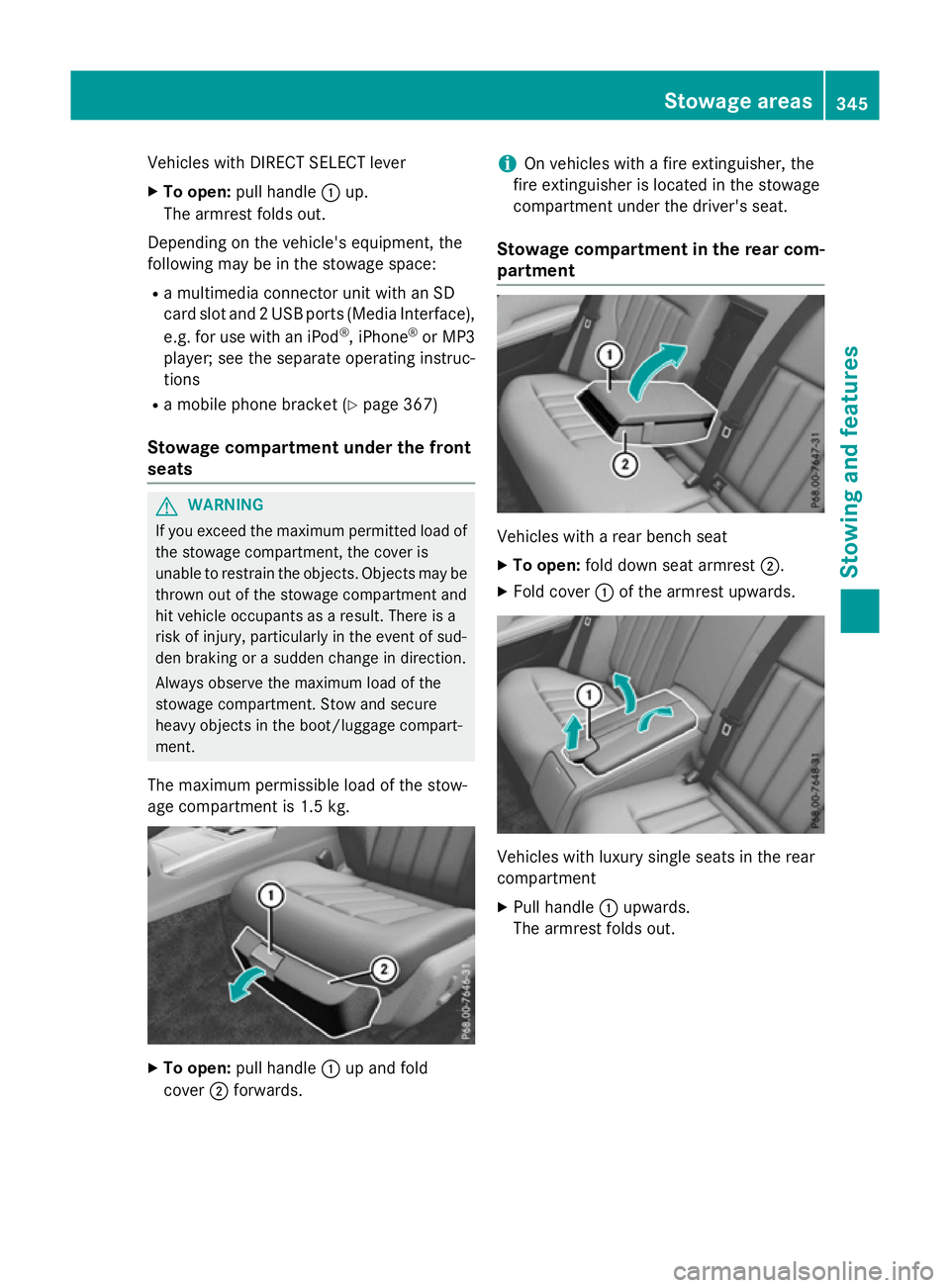
Vehicles with DIRECT SELECT lever
X To open: pull handle :up.
The armrest folds out.
Depending on the vehicle's equipment, the
following may be in the stowage space:
R am ultimediac onnector unit with an SD
card slot and 2USB ports (MediaI nterface),
e.g. for use with an iPod ®
,i Phone ®
or MP3
player; see the separate operating instruc-
tions
R am obile phone bracket (Y page 367)
Stowage compartment under the front
seats G
WARNING
If you exceed the maximum permitted load of the stowage compartment, the cover is
unable to restrain the objects. Objects may be
thrown out of the stowage compartment and
hit vehicle occupants as aresult. There is a
risk of injury, particularly in the event of sud-
den braking or asuddenc hange in direction.
Alwayso bserve the maximum load of the
stowage compartment. Stow and secure
heavy objects in the boot/luggage compart-
ment.
The maximum permissible load of the stow-
age compartment is 1.5 kg. X
To open: pull handle :up and fold
cover ;forwards. i
On vehicles with
afire extinguisher, the
fire extinguisher is located in the stowage
compartment under the driver's seat.
Stowage compartment in the rear com-
partment Vehicles with
arear bench seat
X To open: fold down seat armrest ;.
X Fold cover :of the armrest upwards. Vehicles with luxury single seats in the rear
compartment
X Pull handle :upwards.
The armrest folds out. Stowage areas
345Stowing and features Z
Page 349 of 497
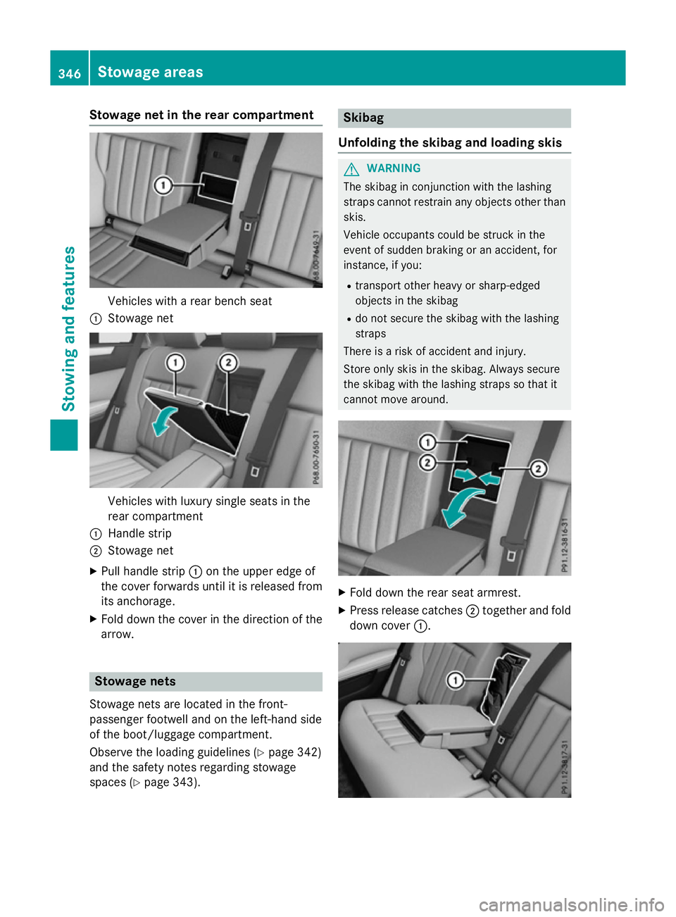
Stowage net in the rear compartment
Vehicles with
arear bench seat
: Stowage net Vehicles with luxury single seats in the
rear compartment
: Handle strip
; Stowage net
X Pull handle strip :on the upper edge of
the cover forwards until it is released from
its anchorage.
X Fold down the cover in the direction of the
arrow. Stowage nets
Stowage nets are located in the front-
passenger footwell and on the left-hands ide
of the boot/luggage compartment.
Observe the loading guidelines (Y page 342)
and the safety notes regarding stowage
spaces (Y page 343). Skibag
Unfolding the skibag and loading skis G
WARNING
The skibag in conjunction with the lashing
straps cannot restrain any objectso ther than
skis.
Vehicle occupants could be struck in the
event of sudden braking or an accident, for
instance, if you:
R transport other heavy or sharp-edged
objectsint he skibag
R do not secure the skibag with the lashing
straps
There is arisk of accident and injury.
Storeo nly skis in the skibag. Always secure
the skibag with the lashing straps so that it
cannot move around. X
Fold down the rear seat armrest.
X Press release catches ;together and fold
down cover :.346
Stowage areasStowing and features