2015 MERCEDES-BENZ E-CLASS SALOON boot
[x] Cancel search: bootPage 416 of 497

X
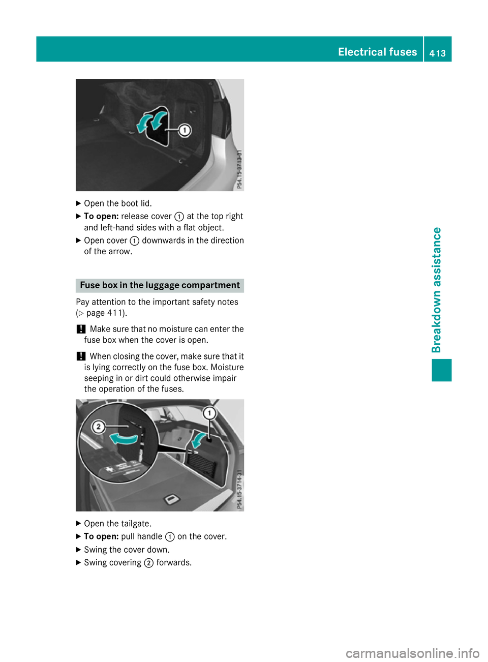
Open the boot lid.
X To open: release cover :at the top right
and left-hand sides with aflat object.
X Open cover :downwards in the direction
of the arrow. Fuse box in the luggage compartment
Pay attention to the important safety notes
(Y page 411).
! Make sure that no moisture can enter the
fuse box when the cover is open.
! When closing the cover, make sure that it
is lying correctly on the fuse box. Moisture seeping in or dirt could otherwise impair
the operation of the fuses. X
Open the tailgate.
X To open: pull handle :on the cover.
X Swing the cover down.
X Swing covering ;forwards. Electrical fuses
413Breakdown assistance Z
Page 431 of 497

jack could tip ove
rwitht he vehicl eraised.
There is ariskofi njury.
Onl yposit iont he jack at the appropriate jack-
ing point of the vehicle. The base of the jack
must be positioned vertically, directl yunder
the jacking point of the vehicle.
Observe the following when raising the vehi-
cle:
R to rais ethe vehicle, onl yusethe vehicle-
specific jack tha thas been teste dand
approved by Mercedes-Benz. If the jack is
used incorrectly ,itcould tip ove rwhile the
vehicl eisraised.
R the jack is designe donlytor aiseand hold
the vehicl efor as hort time whil eawheel
is being changed. It is not suitabl efor per-
formin gmaintenance work under the vehi-
cle.
R avoi dchanging the whee lonuphilland
downhil lslope s.
R befor eraisi ng the vehicle, safeguard it from
rolling away by applying the parking brake
and positioning whee lchocks. Never
release the parking brake whil ethe vehicle
is raised.
R the jack must be place donafirm, flatand
non-sli psurface. On aloo se surface, a
large ,flatl oad- bearing underlay must be
used .Ona slippery surface, anon-slip
underlay must be used ,e.g.r ubbe rmats.
R do not us ewoode nblocks or similar
objects as ajack underlay .Otherwise, the
jack will not be able to achieve its load-
bearing capacity du etothe restricted
height.
R make sure tha tthe distance between the
undersid eofthe tyres and the ground does
not exceed 3cm.
R neve rplace your hands or fee tunder the
raised vehicle.
R do not li eunder the vehicle.
R do not start the engine when the vehicl eis
raised. R
do not open or close adoorort he boot lid/
tailgate when the vehicl eisraised.
R make sure tha tnopersons ar epresent in
the vehicl ewhent he vehicl eisraised.
AM Gvehicle swithP erformanc eStudio
equipment: the wheelbolts ar ecovered by a
hu bc ap.B efore yo ucan unscrew the wheel
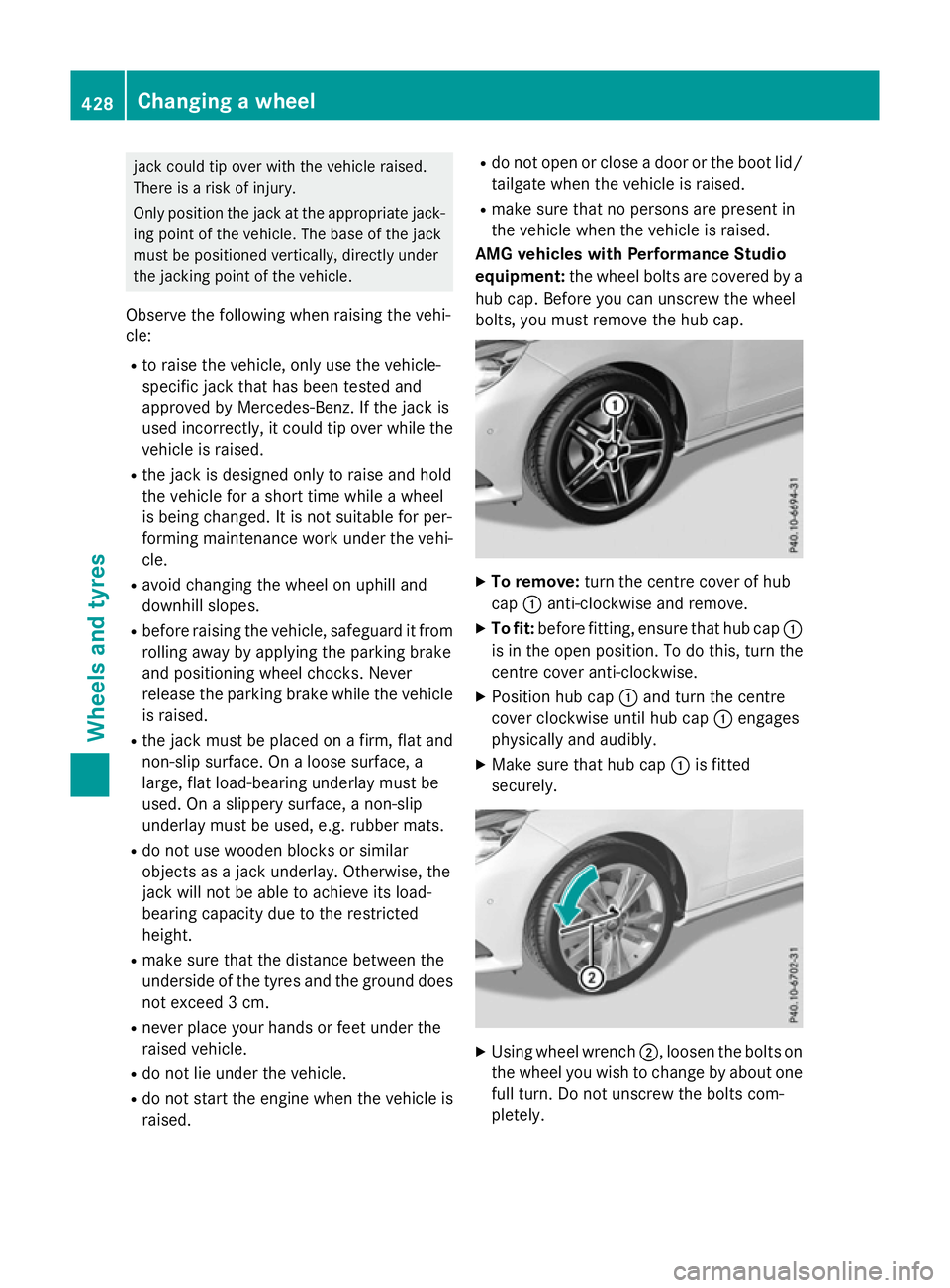
bolts ,you must remove the hu bcap. X
To remove: turnthe centre cove rofhub
cap :anti-clockwise and remove.
X To fit: beforefitting, ensur etha thub cap :
is in the open position. To do this, tur nthe
centre cove ranti-clockwise.
X Positio nhub cap :and tur nthe centre
cove rclockwise unti lhub cap :engages
physicall yand audibly.
X Make sure tha thub cap :is fitted
securely. X
Using whee lwrench ;,l oosent he bolts on
the whee lyou wish to change by abou tone
full turn. Do not unscrew the bolts com-
pletely. 428
Changin
gawheelWheels an dtyres
Page 434 of 497

X
Tighten the wheel bolts evenly in across-
wise pattern in the sequence indicated ( :
to A). The specified tightening torque is
130 Nm.
X Turn the jack back to its initial position.
X Stow the jack and the rest of the tyre-
change tool kit in the boot/luggage com-
partmen tagain.
X AMG vehicles and vehicles with AMG
equipment: insert the cover into the outer
sill.
X Check the air pressure of the newly fitted
wheel and adjust accordingly.
Observe the recommended tyre pressure
(Y page 420).
i Vehicles with
atyre pressure control sys-
tem: all fitted wheels must be equipped
with functioning sensors. Wheel and tyrec
ombinations General notes
! For safety reasons, Mercedes-Benz rec-
ommends that you only use tyres and
wheels which have been approved by
Mercedes-Benz specifically for your vehi-
cle. These are specially adapted to the control
systems, such as ABS or ESP
®
and are
marked as follows:
R MO =Mercedes-Benz Original
R MOE =Mercedes-Benz Original Extended
(tyres featuring run-flat characteristics)
R MO1 =Mercedes-Benz Original (only cer-
tain AMG tyres)
Mercedes-Benz Original Extended tyres
may only be used on wheels that have been
specifically approved by Mercedes-Benz.
Only use tyres, wheels or accessories tes-
ted and approved by Mercedes-Benz.C er-
tain characteristics, e.g. handling, vehicle
noise emissions or fuel consumption, may
otherwise be adversely affected. In addi-
tion, when driving with aload, tyre dimen-
sion variations could cause the tyres to
come into contact with the bodywork and
axle components. This could result in dam- age to the tyres or the vehicle.
Mercedes-Benz accepts no liability for
damage resulting from the use of tyres,
wheels or accessories other than those tes-
ted and approved.
Further information about wheels, tyres
and approved combinations can be
obtained from any qualified specialist
workshop.
! Retreaded tyres are neither tested nor
recommended by Mercedes-Benz,s ince
previous damage cannot alway sbedetec-
ted on retreaded tyres. As aresult,
Mercedes-Benz cannot guarantee vehicle
safety if retreaded tyres are fitted. Do not fit
used tyres if you have no information about their previous usage.
! Large wheels: the lower the section width
for acertain wheel size, the lower the ride
comfor tisonp oor road surfaces. Roll com-
fort and suspension comfor tare reduced
and the risk of damage to the wheels and
tyres as aresult of driving over obstacles
increases. Wheel and tyrec
ombinations
431Wheels and tyres Z
Page 468 of 497

Emergency spare wheel
Important safety notes
G
WARNING
The wheel/tyr edimension sand th etyret ype
of th espar ew heel/emergency spar ewheel
and th ewheel to be replaced may differ. Fit-
tin gas parew heel/emergency spar ewheel
may severel yimpair th edriving characteris-
tics. Ther eisarisk of accident.
To prevent hazardous situations:
R Adap tyour driving style accordingly and
driv ecarefully.
R Never fit mor etha no nespar ewheel/emer-
gency spar ewheel if th edimension sare
differen ttothose of th ewheel being
replaced.
R Only use aspar ew heel/emergency spare
wheel briefly if th edimension sare different
to those of th ewheel bein greplaced.
R Do no tswitch off ESP ®
.
R Hav ethe spar ewheel/emergency spare
wheel in question replaced at th enearest
qualified specialist workshop .Makes ure
that th ewheel/tyr edimension sand tyre
type are correct.
When usin ganemergency spar ewheel or
spar ewheel of adifferen tsize, you must not
exceed th emaximum spee dof80k m/h.
Snow chains must no tbefittedtoe mergency
spar ewheels. General notes
You shoul dregularly check th epressure of all
your tyres, includin gthe emergency spare
wheel, particularly prio rtolongtrips, and cor-
rec tthe pressure as necessary (Y page 420).
The value on th ewheel is valid. In addition ,the
emergency spar ewheel tyr epressure can be
foun dunde r"Technical data" (Y page 468).
An emergency spar ewheel may also be fitted
against th edirection of rotation. Observ ethe
tim erestriction on use as well as th espeed limitatio
nspecified on th eemergency spare
wheel.
Replac ethe tyres after six years at th elatest,
regardless of wear. This also applies to the
emergency spar ewheel.
i If you are driving with th
eemergency
spar ewheel fitted, th etyrep ressure loss
warning system or th etyrep ressure moni-
to rc anno tfunction reliably. Only restart
th et yrep ressure loss warning system/tyre
pressure monito rwhen th edefective wheel
has been replaced with anew wheel.
Vehicle swithatyrep ressure monitor: for a
few minute safter an emergency spare
wheel is fitted, th esystem may still display
th et yrep ressure of th eremove dwheel.
The value displaye dfor th eposition where
th ee mergency spar ewheel is fitte disnot
th es ame as th ecurren ttyrep ressure of the
emergency spar ewheel. Removing th
e"Minispare" emer-
gency spare wheel/collapsible emer-
gency spare wheel
Opening th estowage well Saloon:
thee mergency spar ewheel can be
foun dint hestowage well unde rthe boot
floor.
X Lif tthe boot floo rupwards (Y page 356).
Estate: thee mergency spar ewheel is located
in th estowage well unde rthe luggage com-
partmen tfloor.
X Withou tafolding bench seat: lift up the
EASY-PACK folding load compartmen tfloor
(Y page 357). Emergency spar
ewheel
465Wheels and tyres Z
Page 470 of 497

X
Remove th eprotective film from th evehicle
tool ki tand put it ove rthe collapsible emer-
gency spar ewheel.
X Stow th ecollapsible emergenc yspare
whee lintheemergenc yspar ew hee lwell
under th eboot/luggag ecom partment. Inflating th
ecollapsible emergency
spar ewheel
! Inflat
ethe collapsible emergenc yspare
whee lusin gthe tyreinflation compressor
before lowerin gthe vehicle. The whee lrim
could otherwise be damaged.
! Do no
toperate th etyrei nflation com-
presso rfor longer than eigh tminute sata
time without abreak. It may otherwise
overheat.
The tyr einflation compressor can be oper-
ate dagain once it has cooled down. X
Moun tthe collapsible emergenc yspare
whee lasd escribed (Y page 426).
The collapsible emergenc yspar ew heel
mus tbem ountedbefore it is inflated.
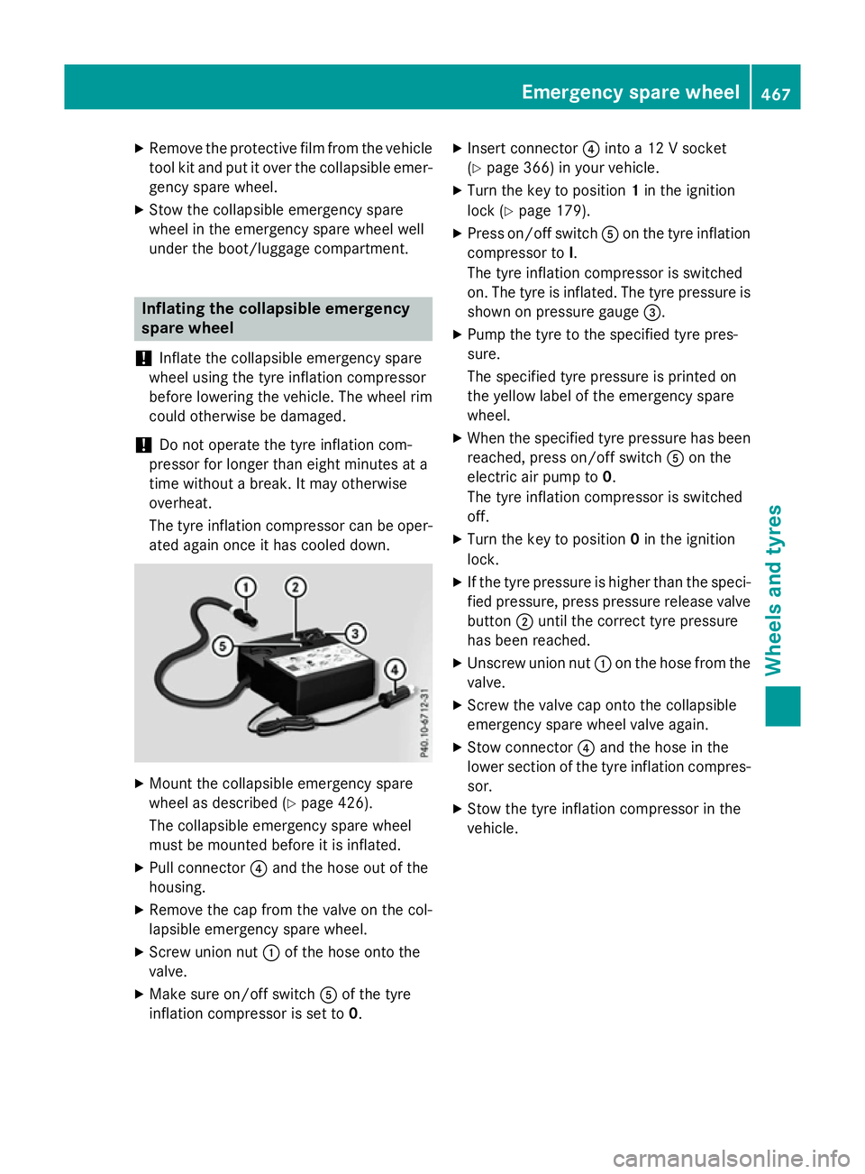
X Pull connector ?and th ehoseo ut of the
housing.
X Remove th ecap from th evalveont hecol-
lapsible emergenc yspar ew heel.
X Screw union nut :of th ehoseo ntot he
valve.
X Mak esureo n/of fswitch Aof th etyre
inflation compressor is set to 0.X
Inser tconnector ?into a12Vs ocket
(Y page 366) in your vehicle.
X Turn th ekeyto position 1in th eignition
loc k(Ypage 179).
X Press on/off switch Aon th etyrei nflation
compressor to I.
The tyr einflation compressor is switched
on .The tyr eisinflated. The tyr epressur eis
shown on pressur egauge =.
X Pump th etyretot hespecified tyr epres-
sure.
The specified tyr epressur eisprinted on
th ey ellow label of th eemergenc yspare
wheel.
X Whe nthe specified tyr epressur ehas been
reached, press on/off switch Aon the
electric air pump to 0.
The tyr einflation compressor is switched
off.
X Turn th ekeyto position 0in th eignition
lock.
X If th etyrep ressur eishigher than th especi-
fie dp ressure, press pressur erelease valve
button ;until th ecorrect tyrep ressure
has been reached.
X Unscrew union nut :on th ehosef romt he
valve.
X Screw th evalvec ap onto th ecollapsible
emergenc yspar ew hee lvalv ea gain.
X Stow connector ?and th ehoseint he
lower section of th etyrei nflation compres-
sor.
X Stow th etyrei nflation compressor in the
vehicle. Emergency spar
ewheel
467Wheels and tyres Z
Page 474 of 497

sion surrounding the possible health risk
posed by electromagnetic fields.
Observe the notes on operating mobile
phones (Y page 367).
The following aerialp ositions may be used for
the correct installation of RF transmitters: Saloon: approved aerial positions
:
Front roof area
; Rear roof area
= Rear wing
? Boot lid Estate: approved aerial positions
:
Front roof area
; Rear roof area
= Rear wing
i When fitting an aerialont
he front roof
area of vehicles with asliding sunroof,
observe the sweeping range of the roof.
On vehicles with panorama sliding sunroof,
fitting an aerialtot he front or rear roof area
is not permitted. On the rear wing, it is recommended that
you position the aerialont he side of the
vehicle closest to the centre of the road.
Use Technical Specification ISO/TS 21609
(RoadV ehicles–"EMC guidelines for fitting
aftermarket radio frequency transmitting
equipment") when retrofitting RF (radio fre-
quency) transmitters. Comply with the legal
requirements for add-on parts.
If your vehicle has fittings for two-way radio
equipment, use the power supplyora erial
connections intended for use with the basic
wiring. Be sure to observe the manufacturer's additional instructions when installing.
Deviations with respect to wavebands, maxi-
mum transmission outputs or aerialp ositions
must be approved by Mercedes-Benz.
The maximum transmission output (PEAK) at
the base of the aerialm ust not exceed the
following values: Waveband Maximum
transmission output Short wave
3-54M
Hz 100 W
4mw
aveband
74 -88M Hz 30 W
2mw
aveband
144 -174 MHz 50 W
Trunked radio/Tetra
380
-460 MHz 10 W
70 cm waveband
400
-460 MHz 35 W
Mobile communications
(2G/3G/4G) 10 WVehicle electronics
471Technical data Z
Page 484 of 497

Vehicl
edata General notes
Please note tha tfor the specified vehicle
data:
R the heights specified ma yvaryasar esult
of:
- tyres
- load
- condition of the suspension
- optional equipment
R optional equipment reduce sthe maximum
payload.
R vehicle-specific weight informatio ncan be
found on the vehicl eide ntificatio nplate
(Y page 472).
R onl yfor certain countries: yo ucan find vehi-
cle-specifi cvehicl edataint he CO Cdocu-
ments (CERTIFICATE OF CONFORMITY).
These documents ar edelive redw ithy our
vehicle. Dimension
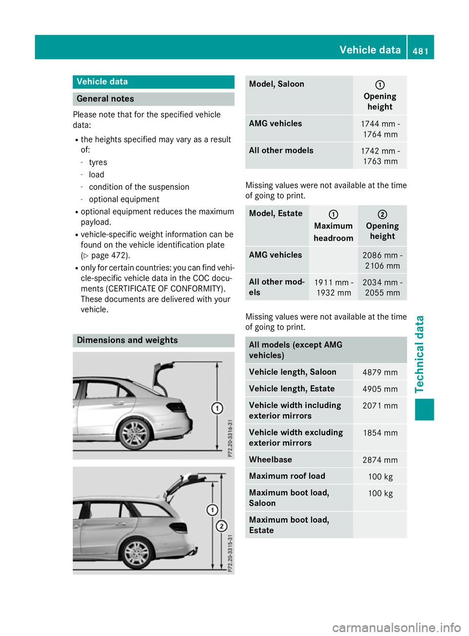
sand weights Model, Saloon
:
:
Opening height AM
Gvehicles 1744 mm -
1764 mm Al
lo the rm odels 1742 mm -
1763 mm Missing values were not availabl
eatthe time
of going to print. Model, Estate
:
:
Maximum
headroom ;
;
Opening height AM
Gvehicles 2086 mm -
2106 mm Al
lo the rm od-
els 1911 mm -
1932 mm 2034 mm -
2055 mm Missing values were not availabl
eatthe time
of going to print. Al
lm odels (except AMG
vehicles) Vehicl
elengt h, Saloon 4879 mm
Vehicl
elengt h, Estate 4905 mm
Vehicl
ewidth including
exterior mirrors 2071 mm
Vehicl
ewidth excluding
exterior mirrors 1854 mm
Wheelbase
2874 mm
Maximum roo
fload 100 kg
Maximum boot load,
Saloon
100 kg
Maximum boot load,
Estate Vehicl
edata
481Technica ldata Z
Page 485 of 497

Model
,Saloon (except
AMG vehicles) Vehicle
height E1
80
E2 00
E2 20 CDI 1474 mm
E2
20 BlueTEC BlueEFFI-
CIENCY Edition 1457 mm
E3
00 4MATIC
E4 00
E400 4MATIC
E2 50 BlueTEC 4MATIC
E3 50 BlueTEC 4MATIC 1477 mm
E5
00
E5 00 4MATIC 1458 mm
All other models
1475 mm
Model
,Estate (except
AMG vehicles) Vehicle
height E2
20 BlueTEC BlueEFFI-
CIENCY Edition 1494 mm
E2
50 BlueTEC 4MATIC
E3 50 BlueTEC 4MATIC 1509 mm
E5
00
E5 00 4MATIC 1511 mm
All other models
1507 mm
Missing values were not available at the time
of going to print. AMG vehicles
Vehicle width including
exterio rmirrors 2071 mm
Vehicle width excluding
exterio rmirrors 1873 mm
Wheelbase
2874 mm AMG vehicles
Maximum roof load
100 kg
Maximum bootl
oad,
Saloon Maximum bootl
oad,
Estate AMG vehicles Vehicle
length Saloon
4892 mm
Estate
4904 mm
E63A
MG
E63A MG S-MODEL Vehicle
height Saloon
1450 mm
Estate
1502 mm
E63A
MG 4MATIC
E63A MG S-MODEL
4MATIC Vehicle
height Saloon
1466 mm
Estate
1522 mm
Trailer tow hitch
Mountin
gdimensions
! If you have
atrailer tow hitch retrofitted,
changes to the engine cooling system may
be necessary, depending on the vehicle
type.
If you have atrailer tow hitch retrofitted,
observe the anchorage points on the chas- sis. 482
Trailer tow hitchTechnical data E2
20 BlueTEC 4MATIC/
E4 00
E400 4MATIC
/
E2 20 BlueTEC 4MATIC