2015 MERCEDES-BENZ E-CLASS CABRIOLET tow bar
[x] Cancel search: tow barPage 20 of 349

Safety system
see Driving safety systems
SD memory card
Ejecting .......................................... 270
Inserting ........................................2 70
Inserting/removing ........................ 270
See also Digital Owner's Manual ... 263
Selecting ........................................ 218
Seat
Adjusting the multicontour seat ..... 104
Seat backrest display message ..... 250
Seat belt
Automatic comfort-fit feature .......... 41
Correct usage .................................. 40
Switching belt adjustment on/off
(on-board computer) ..................... .227
Seat belts
Adjusting the driver's and front-
passenger seat bel t......................... 41
Cleaning ......................................... 303
Display message ............................ 234
Fastening ......................................... 40
Important safety guidelines ............. 39
Introduction ..................................... 38
Rear seat belt status indicator ......... 42
Releasing ......................................... 41
Warning lamp ................................. 254
Warning lamp (function) ................... 42
Seats
Adjusting (electrically) ................... 101
Adjusting (manually and electri-
cally ).............................................. 100
Adjusting the 4-way lumbar sup-
port ................................................ 104
Adjusting the head restraint .......... 101
Cleaning the cover ......................... 302
Correct driver's seat position ........... 99
Folding the backrests forward/
back ............................................... 103
Important safety notes .................... 99
Overview .......................................... 99
Seat heating .................................. 104
Seat heating problem .................... 106
Storing settings (memory func-
tion) ............................................... 112
Switching AIRSCARF on/of f.......... 106
Switching seat heating on/of f....... 104 Switching the seat ventilation on/
off .................................................. 105
Section
Boot ................................................. 82
Securing a load
see Stowage space
Securing luggage ............................... 276
Selector lever
Cleaning ......................................... 302
Sensors (cleaning instructions) ....... 300
Service
see ASSYST PLUS
Service Centre
see Qualified specialist workshop
Service menu (on-board com-
puter) .................................................. 222
Service message
see ASSYST PLUS
Service products
AdBlue ®
special additive s.............. 340
Brake fluid ..................................... 341
Coolant (engine) ............................ 341
Engine oil ....................................... 340
Fuel ................................................ 337
Important safety notes .................. 337
Washer fluid ................................... 342
Setting the air distribution ............... 128
Setting the airflow ............................ 129
Setting the date/time format
See also Digital Owner's Manua l... 263
Setting the language
See also Digital Owner's Manua l... 263
Setting the time
See also Digital Owner's Manua l... 263
Settings
Factory (on-board computer) ......... 228
On-board compute r....................... 223
Side lamps
Switching on/of f........................... 115
Side windows
Important safety notes .................... 84
Opening/closing .............................. 85
Opening/closing all ......................... 86
Problem (malfunction) ..................... 88
Resetting ......................................... 87
Reversing feature ............................. 85
Sidebag ................................................ 44 Index
17
Page 48 of 349
Pelvisbags
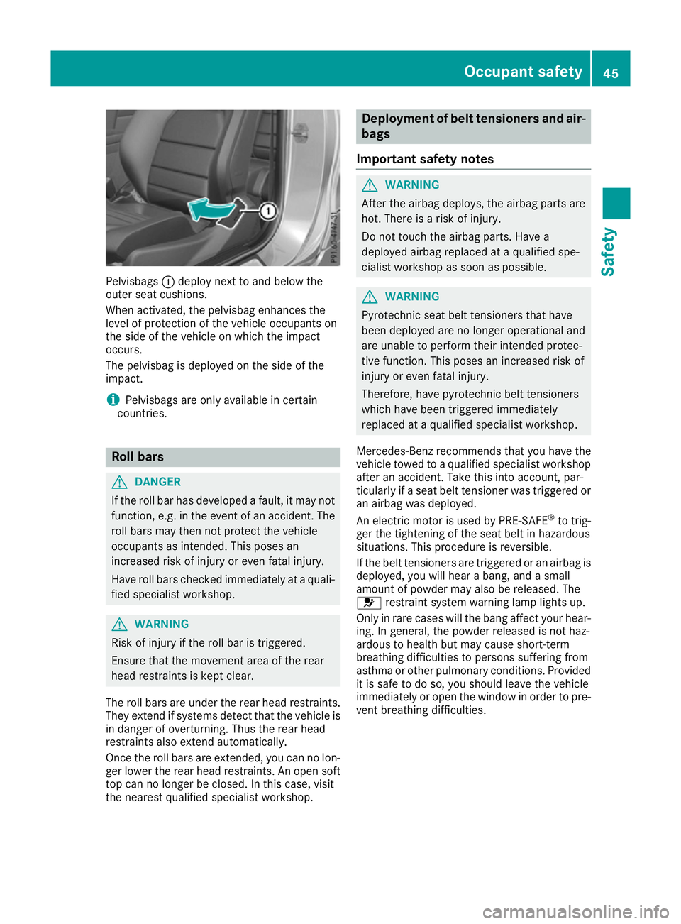
:deploy next to and below the
outer seat cushions.
When activated, the pelvisbag enhances the
level of protection of the vehicle occupants on
the side of the vehicle on which the impact
occurs.
The pelvisbag is deployed on the side of the
impact.
i Pelvisbags are only available in certain
countries. Roll bars
G
DANGER
If the roll bar has developed a fault, it may not function, e.g. in the event of an accident. The
roll bars may then not protect the vehicle
occupants as intended. This poses an
increased risk of injury or even fatal injury.
Have roll bars checked immediately at a quali-
fied specialist workshop. G
WARNING
Risk of injury if the roll bar is triggered.
Ensure that the movement area of the rear
head restraints is kept clear.
The roll bars are under the rear head restraints. They extend if systems detect that the vehicle isin danger of overturning. Thus the rear head
restraints also extend automatically.
Once the roll bars are extended, you can no lon-
ger lower the rear head restraints. An open soft
top can no longer be closed. In this case, visit
the nearest qualified specialist workshop. Deployment of belt tensioners and air-
bags
Important safety notes G
WARNING
After the airbag deploys, the airbag parts are
hot. There is a risk of injury.
Do not touch the airbag parts. Have a
deployed airbag replaced at a qualified spe-
cialist workshop as soon as possible. G
WARNING
Pyrotechnic seat belt tensioners that have
been deployed are no longer operational and
are unable to perform their intended protec-
tive function. This poses an increased risk of
injury or even fatal injury.
Therefore, have pyrotechnic belt tensioners
which have been triggered immediately
replaced at a qualified specialist workshop.
Mercedes-Benz recommends that you have the
vehicle towed to a qualified specialist workshop
after an accident. Take this into account, par-
ticularly if a seat belt tensioner was triggered or
an airbag was deployed.
An electric motor is used by PRE-SAFE ®
to trig-
ger the tightening of the seat belt in hazardous
situations. This procedure is reversible.
If the belt tensioners are triggered or an airbag is deployed, you will hear a bang, and a small
amount of powder may also be released. The
6 restraint system warning lamp lights up.
Only in rare cases will the bang affect your hear-
ing. In general, the powder released is not haz-
ardous to health but may cause short-term
breathing difficulties to persons suffering from
asthma or other pulmonary conditions. Provided
it is safe to do so, you should leave the vehicle
immediately or open the window in order to pre- vent breathing difficulties. Occupant safety
45Safety Z
Page 163 of 349

ECO display assists you in achieving the most
economical driving style for the selected set-
tings and prevailing conditions. Consumption
can be significantly influenced by your driving
style.
The ECO display consists of three bars:
R Acceleration
Acceleration
R Constant Constant
R Coasting
Coasting
The percentage count is the mean value of the
three bar values. The three bars and the mean
value begin at the value of 50%. A higher per-
centage count indicates a more economical
driving style.
The ECO display does not indicate the actual fuel
consumption. A fixed percentage count in the
ECO display does not indicate a fixed consump- tion.
In addition to driving style, the consumption is
affected by many other factors, such as:
R load
R tyre pressure
R cold start
R choice of route
R the use of electrical consumers
These factors are not included in the ECO dis-
play.
The evaluation of your driving style takes the
following three categories into consideration:
R Acceleration Acceleration (evaluation of all acceleration
processes):
- the bar fills up: moderate acceleration,
especially at higher speeds
- the bar empties: sporty acceleration
R Constant Constant (assessment of driving behaviour
at all times):
- the bar fills up: constant speed and avoid-
ance of unnecessary acceleration and
deceleration
- the bar empties: fluctuations in speed
R Coasting Coasting (assessment of all deceleration
processes):
- the bar fills up: anticipatory driving, keep-
ing your distance and early release of the
accelerator. The vehicle can coast without
use of the brakes.
- the bar empties: frequent braking
i An economical driving style involves driving
at a moderate engine speed. To achieve a higher value in the categories
Acceleration
Acceleration andConstant Constant:
R observe the gearshift recommendation
R drive the vehicle in drive program E(vehi-
cles with automatic transmission)
i On long journeys at a constant speed, e.g.
on the motorway, only the bar for Constant
Constant
will change.
i The ECO display summarises the driving
characteristics from the start of the journey to
its completion. Therefore, there are dynamic
changes in the bars at the start of a journey.
During a prolonged driving time, these
changes are smaller. For more dynamic
changes, perform a manual reset.
Further information on the ECO display
(Y page 216). Brakes
Important safety notes G
WARNING
If you shift down on a slippery road surface in an attempt to increase the engine's braking
effect, the drive wheels could lose their grip.
This increases the risk of skidding and having
an accident.
Do not shift down for additional engine brak-
ing on a slippery road surface.
Downhill gradients Do not depress the brake pedal continuously
while the vehicle is in motion, e.g. never cause
the brakes to rub by constantly applying light
pressure to the pedal. This results in excessive
and premature wear to the brake pads.
Change into a lower gear in good time on long
and steep downhill gradients.
Take particular note of this when driving a laden vehicle and when towing a trailer.
i This also applies if you have activated cruise
control, SPEEDTRONIC or DISTRONIC PLUS.
This will use the braking effect of the engine, so
less braking will be required to maintain vehicle
speed. This relieves the load on the brake sys-
tem and prevents the brakes from overheating
and wearing too quickly. 160
Driving
tipsDriving an d parking
Page 192 of 349
The image from the reversing camera is avail-
able throughout the manoeuvring process.
X To switch the function mode for vehicles
with trailer tow hitch: using the controller,
select symbol :for the "Reverse parking"
function or symbol ;for "Coupling up a
trailer".
The symbol of the selected function is high-
lighted.
To deactivate: the reversing camera deacti-
vates if you shift the transmission to Por after
driving forwards a short distance.
Messages in the multimedia system dis-
play The reversing camera may show a distorted view
of obstacles or show them incorrectly or not at
all. Obstacles are not shown by the reversing
camera in the following locations:
R very close to the rear bumper
R under the rear bumper
R in the area immediately above the tailgate
handle
! Objects not at ground level may appear to
be further away than they actually are, e.g.:
R the bumper of a parked vehicle
R the drawbar of a trailer
R the ball coupling of a trailer tow hitch
R the rear section of an HGV
R a slanted post
Use the guidelines only for orientation.
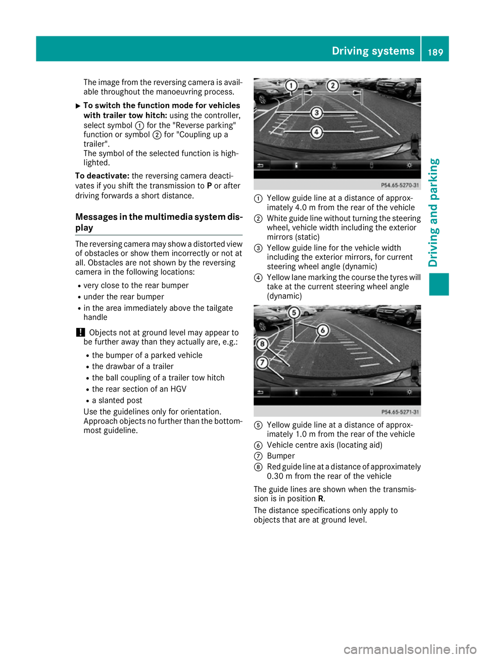
Approach objects no further than the bottom- most guideline. :
Yellow guide line at a distance of approx-
imately 4.0 m from the rear of the vehicle
; White guide line without turning the steering
wheel, vehicle width including the exterior
mirrors (static)
= Yellow guide line for the vehicle width
including the exterior mirrors, for current
steering wheel angle (dynamic)
? Yellow lane marking the course the tyres will
take at the current steering wheel angle
(dynamic) A
Yellow guide line at a distance of approx-
imately 1.0 m from the rear of the vehicle
B Vehicle centre axis (locating aid)
C Bumper
D Red guide line at a distance of approximately
0.30 m from the rear of the vehicle
The guide lines are shown when the transmis-
sion is in position R.
The distance specifications only apply to
objects that are at ground level. Driving systems
189Driving and parking Z
Page 194 of 349
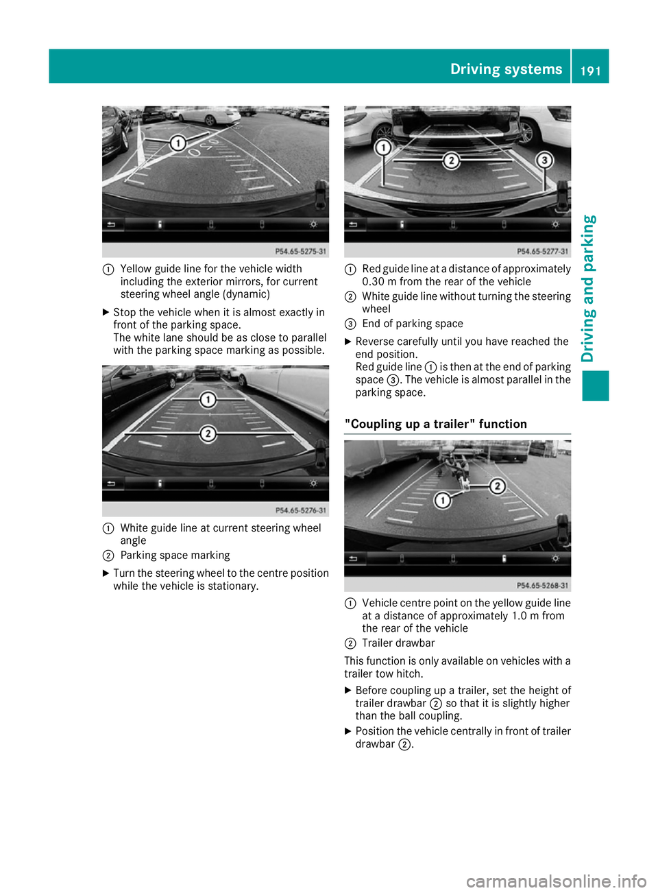
:
Yellow guide line for the vehicle width
including the exterior mirrors, for current
steering wheel angle (dynamic)
X Stop the vehicle when it is almost exactly in
front of the parking space.
The white lane should be as close to parallel
with the parking space marking as possible. :
White guide line at current steering wheel
angle
; Parking space marking
X Turn the steering wheel to the centre position
while the vehicle is stationary. :
Red guide line at a distance of approximately
0.30 m from the rear of the vehicle
; White guide line without turning the steering
wheel
= End of parking space
X Reverse carefully until you have reached the
end position.
Red guide line :is then at the end of parking
space =. The vehicle is almost parallel in the
parking space.
"Coupling up a trailer" function :
Vehicle centre point on the yellow guide line
at a distance of approximately 1.0 m from
the rear of the vehicle
; Trailer drawbar
This function is only available on vehicles with a
trailer tow hitch.
X Before coupling up a trailer, set the height of
trailer drawbar ;so that it is slightly higher
than the ball coupling.
X Position the vehicle centrally in front of trailer
drawbar ;. Driving systems
191Driving and parking Z
Page 195 of 349

:
Red guide line at a distance of approximately
0.30 m from the ball coupling
; Trailer drawbar locating aid
= Trailer drawbar
? Symbol for the "Coupling up a trailer" func-
tion
A Ball coupling
i For technical reasons, the ball coupling of
the trailer tow hitch in the multimedia system
display is either only partially visible or not at all.
X Select symbol ?using the controller.
The "Coupling up a trailer" function is selec-
ted. The distance specifications now only
apply to objects that are at the same level as the ball coupling.
X Reverse carefully, making sure that trailer
drawbar locating aid ;points approximately
in the direction of trailer drawbar =.
X Reverse carefully until trailer drawbar =rea-
ches the red guide line.
The distance between the trailer drawbar and the red guide line is now approximately
0.30 m.
X Couple up the trailer (Y page 209).Wide-angle function :
Symbol for the wide-angle view function
; Own vehicle
= PARKTRONIC warning displays
You can also use the reversing camera to select
a wide-angle view.
When PARKTRONIC is operational (Y page 181),
a symbol for your own vehicle appears in the
display of the multimedia system. If the
PARKTRONIC warning displays are active, warn-
ing displays =light up in the multimedia system
in yellow or red accordingly. 360° camera
General notes The 360° camera is a system that consists of
four cameras.
The system evaluates images from the following
cameras:
R Reversing camera
R Front camera
R Two cameras in the exterior mirrors
The cameras cover the immediate surroundings
of the vehicle. The system assists you, for
instance when parking or at exits with reduced
visibility.
You can show pictures from the 360° camera in
full-screen mode or in seven different split-
screen views on the multimedia system display. A split-screen view also includes a top view of
the vehicle. This view is calculated from the data
supplied by the installed cameras (virtual cam-
era).
The seven split-screen views are: 192
Driving systemsDriving and pa
rking
Page 197 of 349
R
a split-screen with top view and the image
from the front camera or
R a split-screen with top view and the image
from the reversing camera
or
X Press the Øbutton in the centre console.
The vehicle menu appears.
X Select 360°
360° camera
camera and press 7to confirm.
The following appears depending on whether transmission position Dor Ris selected:
R a split-screen with top view and the image
from the front camera or
R a split-screen with top view and the image
from the reversing camera
Switching on the 360° camera using
reverse gear You can show images from the 360° camera
automatically by engaging reverse gear.
X Make sure that the key is in position 2in the
ignition lock.
X Make sure that the Activation by R gear
Activation by R gear
function is selected in the multimedia system (see the separate operating instructions).
X To show the 360° camera image: engage
reverse gear.
The area behind the vehicle is shown in the
multimedia system display in split-screen
mode. You see the top view of the vehicle and the image from the reversing camera.
Selecting the split-screen and full
screen displays Switching between split screen views
X To switch to the line with the vehicle icons:
slide 5the controller.
X To select one of the vehicle icons: turn 3
the controller.
X To switch to 180° view
180° view :turn 3 the con-
troller to select 180° view
180° view and press7to
confirm.
i The
180°
180° view viewoption is only available in the
following views:
R Top view with image from the reversing
camera
R Top view with image from the front camera Messages in the multimedia system dis-
play Important safety notes
The system may show a distorted view of obsta-
cles or show them incorrectly or not at all.
Obstacles are not shown by the system in the
following locations:
R under the front and rear bumpers
R very close to the front and rear bumpers
R in the area immediately above the handle on
the boot lid
R very close to the exterior mirrors
R in the transitional areas between the various
cameras in the virtual top view
! Objects not at ground level may appear to
be further away than they actually are, e.g.:
R the bumper of a parked vehicle
R the drawbar of a trailer
R the ball coupling of a trailer tow hitch
R the rear section of an HGV
R a slanted post
Use the guidelines only for orientation.
Approach objects no further than the bottom- most guideline.
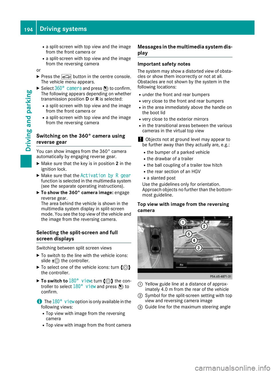
Top view with image from the reversing
camera :
Yellow guide line at a distance of approx-
imately 4.0 m from the rear of the vehicle
; Symbol for the split-screen setting with top
view and reversing camera image
= Guide line for the maximum steering angle 194
Driving systemsDriving and parking
Page 208 of 349
The yellow indicator lamp goes out if reverse
gear is engaged. Active Blind Spot Assist is not
operational.
The brightness of the warning lamps is auto-
matically adapted to the brightness of the sur-
roundings.
Visual and acoustic collision warning
If you switch on the turn signals to change lanes
and a vehicle is detected in the side monitoring range, you receive a visual and acoustic collision
warning. You then hear a double warning tone
and red warning lamp :flashes. If the turn sig-
nal remains on, detected vehicles are indicated
by the flashing of red warning lamp :. There are
no further warning tones.
Course-correcting brake application
If Active Blind Spot Assist detects a risk of a side
impact in the monitoring range, a course-cor-
recting brake application is carried out. This is
designed to help you avoid a collision. G
WARNING
A course-correcting brake application cannot always prevent a collision. There is a risk of an
accident.
Always steer, brake or accelerate yourself,
especially if Active Blind Spot Assist warns
you or makes a course-correcting brake appli-
cation. Always maintain a safe distance at the sides. If a course-correcting brake application occurs,
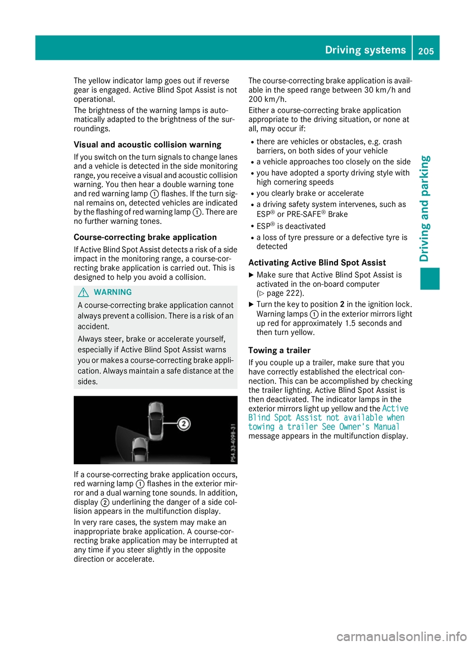
red warning lamp :flashes in the exterior mir-
ror and a dual warning tone sounds. In addition, display ;underlining the danger of a side col-
lision appears in the multifunction display.
In very rare cases, the system may make an
inappropriate brake application. A course-cor-
recting brake application may be interrupted at
any time if you steer slightly in the opposite
direction or accelerate. The course-correcting brake application is avail-
able in the speed range between 30 km/h and
200 km/h.
Either a course-correcting brake application
appropriate to the driving situation, or none at
all, may occur if:
R there are vehicles or obstacles, e.g. crash
barriers, on both sides of your vehicle
R a vehicle approaches too closely on the side
R you have adopted a sporty driving style with
high cornering speeds
R you clearly brake or accelerate
R a driving safety system intervenes, such as
ESP ®
or PRE-SAFE ®
Brake
R ESP ®
is deactivated
R a loss of tyre pressure or a defective tyre is
detected
Activating Active Blind Spot Assist
X Make sure that Active Blind Spot Assist is
activated in the on-board computer
(Y page 222).
X Turn the key to position 2in the ignition lock.
Warning lamps :in the exterior mirrors light
up red for approximately 1.5 seconds and
then turn yellow.
Towing a trailer
If you couple up a trailer, make sure that you
have correctly established the electrical con-
nection. This can be accomplished by checking
the trailer lighting. Active Blind Spot Assist is
then deactivated. The indicator lamps in the
exterior mirrors light up yellow and the Active
Active
Blind Spot Assist not available when Blind Spot Assist not available when
towing a trailer See Owner's Manual towing a trailer See Owner's Manual
message appears in the multifunction display. Driving systems
205Driving and parking Z