2015 MERCEDES-BENZ E-CLASS CABRIOLET tow bar
[x] Cancel search: tow barPage 211 of 349
R
you have switched on the turn signal. In this
case, the warnings are suppressed for a
certain period of time.
R a driving safety system intervenes, such as
ABS, BAS or ESP ®
.
When Adaptive
Adaptive is selected, no warning vibra-
tion occurs if:
R you have switched on the turn signal. In this
case, the warnings are suppressed for a
certain period of time.
R a driving safety system intervenes, such as
ABS, BAS or ESP ®
.
R you accelerate hard, e.g. kickdown.
R you brake hard.
R you steer actively, e.g. swerve to avoid an
obstacle or change lane quickly.
R you cut the corner on a sharp bend.
In order that you are warned only when neces-
sary and in good time if you cross the lane mark-
ing, the system detects certain conditions and
warns you accordingly.
The warning vibration occurs earlier if:
R you approach the outer lane marking on a
bend
R the road has very wide lanes, e.g. a motorway
R the system detects solid lane markings
The warning vibration occurs later if:
R the road has narrow lanes
R you cut the corner on a bend
Towing a trailer If you couple up a trailer, make sure that you
have correctly established the electrical con-
nection. This can be accomplished by checking
the trailer lighting. Towing a trailer
Important safety notes
G
WARNING
You could lose control of the vehicle/trailer
combination if it begins to swerve. The vehi-
cle/trailer combination could even overturn.
There is a risk of an accident.
On no account should you attempt to
straighten out the vehicle/trailer combina-
tion by increasing speed. Decrease your speed and do not countersteer. Brake if nec-
essary. G
WARNING
If the maximum permissible load for a carrier system is exceeded, the carrier could come
loose from the vehicle and endanger other
road users. There is a risk of an accident and injury.
Never exceed the maximum permissible load
when using a carrier.
Exceeding the maximum permissible nose-
weight of the trailer drawbar on the ball coupling
may cause damage to the following:
R your vehicle
R trailer
R the ball coupling
R trailer tow hitch
The vehicle/trailer combination could become
unstable.
If the noseweight used is lower than the mini-
mum permissible noseweight, the vehicle/
trailer combination could also become unstable.
To avoid hazardous situations:
R make sure to check the noseweight before
each journey
R use a drawbar noseweight as close as possi-
ble to the maximum noseweight
R do not exceed the maximum permissible
noseweight
R do not use a noseweight lower than the min-
imum noseweight
When reversing the vehicle towards the trailer,
make sure there is nobody between the trailer
and the vehicle.
Couple and uncouple the trailer carefully. If you do not couple the trailer to the towing vehicle
correctly, the trailer could become detached.
Make sure that the following values are not
exceeded:
R the permissible trailer drawbar noseweight
R the permissible trailer load
R the permissible rear axle load of the towing
vehicle
R the maximum permissible gross vehicle
weight of both the towing vehicle and the
trailer 208
Towing a trailerDriving and pa
rking
Page 212 of 349

You will find the applicable permissible values,
which must not be exceeded, in the vehicle
documents.
You will find the values approved by the manu-
facturer on the vehicle identification plates and
those for the towing vehicle under "Technical
data" (Y page 344).
When towing a trailer, your vehicle's handling
characteristics will be different in comparison to
when driving without a trailer.
The vehicle/trailer combination:
R is heavier
R is restricted in its acceleration and gradient-
climbing capability
R has an increased braking distance
R is affected more by strong crosswinds
R demands more sensitive steering
R has a larger turning circle
This can impair the vehicle's handling charac-
teristics. Adapt your driving style accordingly.
Maintain a safe distance. Drive carefully.
When towing a trailer, always adjust your speed to the current road and weather conditions. Do
not exceed the maximum permissible speed for
your vehicle/trailer combination. Notes on towing a trailer
General notes The E 500 model cannot be used to tow a trailer.
i When towing a trailer, set the tyre pressure
on the rear axle of the towing vehicle for a
maximum load; see the tyre pressure table in
the fuel filler flap (Y page 324).
Please note that when towing a trailer, the fol-
lowing driving systems have limited availability
or are not available at all.
R PARKTRONIC (Y page 179)
R Active Parking Assist (Y page 183)
R Blind Spot Assist (Y page 200)
i The height of the ball coupling changes with
the load of the vehicle. If necessary, use a
trailer with a height-adjustable drawbar.
You will find fitting dimensions and loads under "Technical data" (Y page 343). Driving tips i
Observe the notes on ESP ®
trailer stabilisa-
tion (Y page 68).
The maximum permissible speed for vehicle/
trailer combinations depends on the type of
trailer. Before beginning the journey, check the
trailer's documents to see what the maximum
permitted speed is. Observe the legally prescri-
bed maximum speed in the relevant country.
For certain Mercedes-Benz vehicles, the maxi-
mum permissible rear axle load is increased
when towing a trailer. See the "Technical data"
section to find out whether this applies to your
vehicle (Y page 344). If you utilise any of the
added maximum rear axle load when towing a
trailer, the vehicle/trailer combination may not
exceed a maximum speed of 100 km/h for rea-
sons concerning the operating permit. This also applies in countries in which the permissible
maximum speed for vehicle/trailer combina-
tions is above 100 km/h.
When towing a trailer, your vehicle's handling
characteristics will be different in comparison to
when driving without a trailer and it will con-
sume more fuel.
Change into a lower gear in good time on long
and steep downhill gradients.
i This also applies if you have activated cruise
control, SPEEDTRONIC or DISTRONIC PLUS.
This will use the braking effect of the engine, so
less braking will be required to maintain vehicle speed. This relieves the load on the brake sys-
tem and prevents the brakes from overheating
and wearing too quickly. If you need additional
braking, depress the brake pedal repeatedly
rather than continuously.
Driving tips If the trailer swings from side to side:
X Do not accelerate.
X Do not countersteer.
X Brake if necessary.
R Maintain a greater distance to the vehicle in
front than when driving without a trailer.
R Avoid braking abruptly. If possible, brake gen-
tly at first to allow the trailer to run on. Then,
increase the braking force rapidly.
R The values given for gradient-climbing capa-
bilities from a standstill refer to sea level.
When driving in mountainous areas, note that Towing a trailer
209Driving and parking Z
Page 214 of 349
Folding in the ball coupling
i
Fold the ball coupling back in if you are not
using the trailer tow hitch.
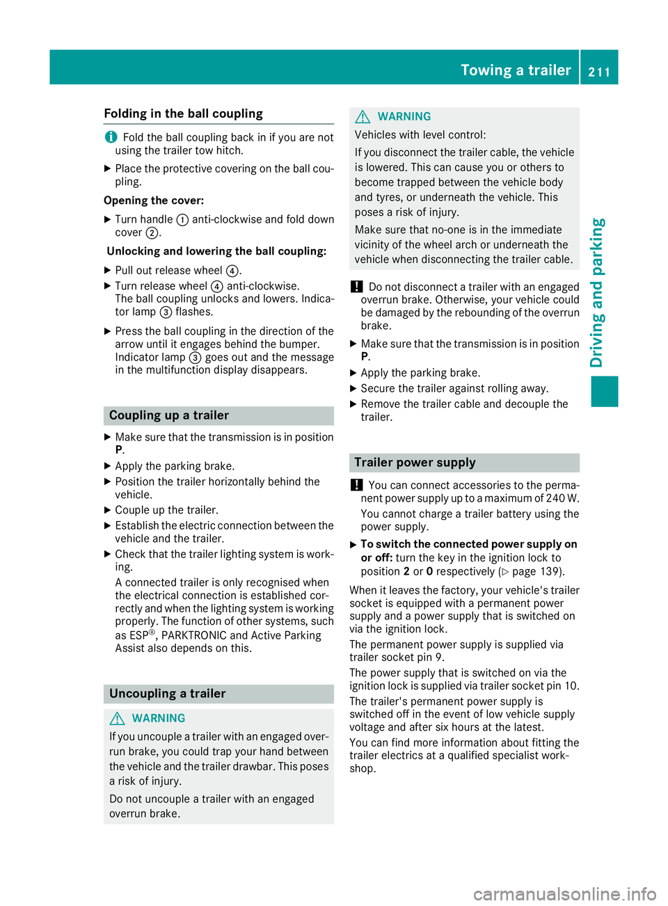
X Place the protective covering on the ball cou-
pling.
Opening the cover: X Turn handle :anti-clockwise and fold down
cover ;.
Unlocking and lowering the ball coupling:
X Pull out release wheel ?.
X Turn release wheel ?anti-clockwise.
The ball coupling unlocks and lowers. Indica-
tor lamp =flashes.
X Press the ball coupling in the direction of the
arrow until it engages behind the bumper.
Indicator lamp =goes out and the message
in the multifunction display disappears. Coupling up a trailer
X Make sure that the transmission is in position
P .
X Apply the parking brake.
X Position the trailer horizontally behind the
vehicle.
X Couple up the trailer.
X Establish the electric connection between the
vehicle and the trailer.
X Check that the trailer lighting system is work-
ing.
A connected trailer is only recognised when
the electrical connection is established cor-
rectly and when the lighting system is working
properly. The function of other systems, such
as ESP ®
, PARKTRONIC and Active Parking
Assist also depends on this. Uncoupling a trailer
G
WARNING
If you uncouple a trailer with an engaged over- run brake, you could trap your hand between
the vehicle and the trailer drawbar. This poses a risk of injury.
Do not uncouple a trailer with an engaged
overrun brake. G
WARNING
Vehicles with level control:
If you disconnect the trailer cable, the vehicle is lowered. This can cause you or others to
become trapped between the vehicle body
and tyres, or underneath the vehicle. This
poses a risk of injury.
Make sure that no-one is in the immediate
vicinity of the wheel arch or underneath the
vehicle when disconnecting the trailer cable.
! Do not disconnect a trailer with an engaged
overrun brake. Otherwise, your vehicle could
be damaged by the rebounding of the overrun
brake.
X Make sure that the transmission is in position
P.
X Apply the parking brake.
X Secure the trailer against rolling away.
X Remove the trailer cable and decouple the
trailer. Trailer power supply
! You can connect accessories to the perma-
nent power supply up to a maximum of 240 W.
You cannot charge a trailer battery using the
power supply.
X To switch the connected power supply on
or off: turn the key in the ignition lock to
position 2or 0respectively (Y page 139).
When it leaves the factory, your vehicle's trailer
socket is equipped with a permanent power
supply and a power supply that is switched on
via the ignition lock.
The permanent power supply is supplied via
trailer socket pin 9.
The power supply that is switched on via the
ignition lock is supplied via trailer socket pin 10.
The trailer's permanent power supply is
switched off in the event of low vehicle supply
voltage and after six hours at the latest.
You can find more information about fitting the
trailer electrics at a qualified specialist work-
shop. Towing a trailer
211Driving and parking Z
Page 290 of 349
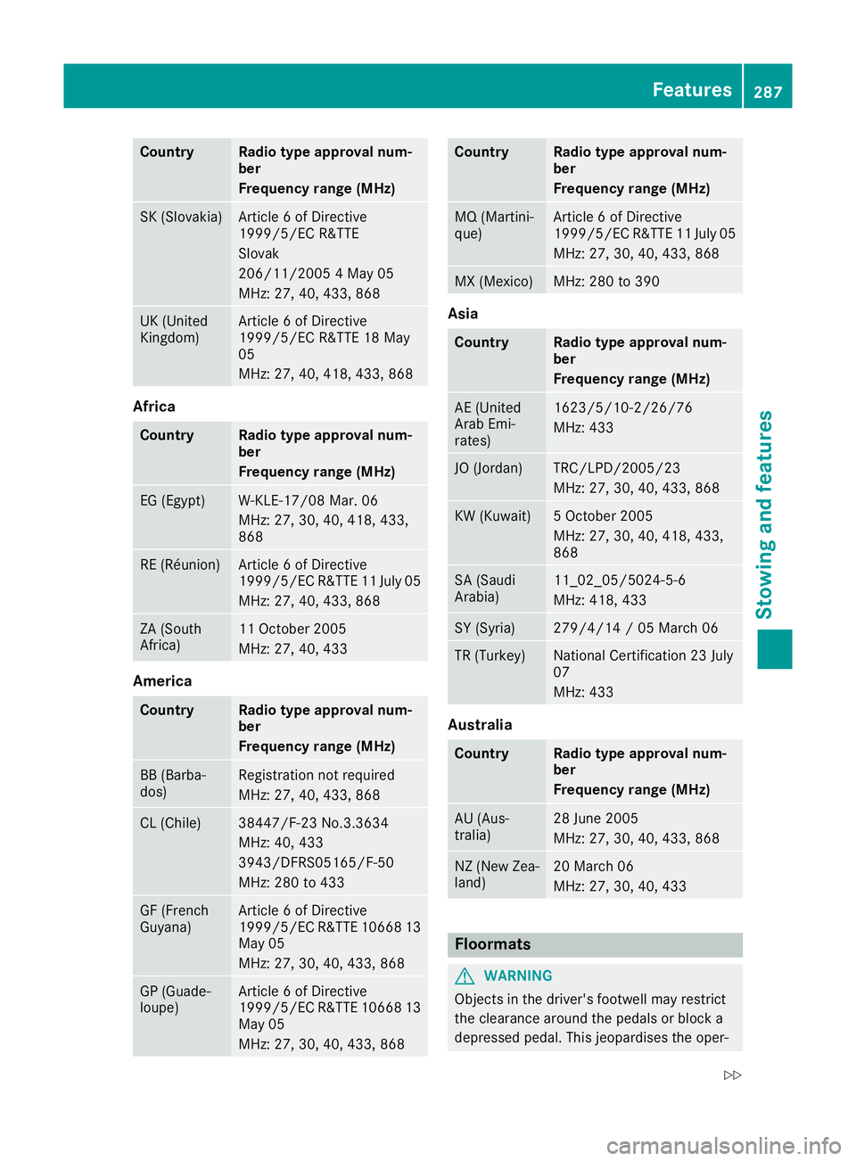
Country Radio type approval num-
ber
Frequency range (MHz)
SK (Slovakia) Article 6 of Directive
1999/5/EC R&TTE
Slovak
206/11/2005 4 May 05
MHz: 27, 40, 433, 868 UK (United
Kingdom) Article 6 of Directive
1999/5/EC R&TTE 18 May
05
MHz: 27, 40, 418, 433, 868
Africa
Country Radio type approval num-
ber
Frequency range (MHz)
EG (Egypt) W-KLE-17/08 Mar. 06
MHz: 27, 30, 40, 418, 433,
868
RE (Réunion) Article 6 of Directive
1999/5/EC R&TTE 11 July 05
MHz: 27, 40, 433, 868 ZA (South
Africa) 11 October 2005
MHz: 27, 40, 433
America
Country Radio type approval num-
ber
Frequency range (MHz)
BB (Barba-
dos) Registration not required
MHz: 27, 40, 433, 868
CL (Chile) 38447/F-23 No.3.3634
MHz: 40, 433
3943/DFRS05165/F-50
MHz: 280 to 433
GF (French
Guyana) Article 6 of Directive
1999/5/EC R&TTE 10668 13
May 05
MHz: 27, 30, 40, 433, 868 GP (Guade-
loupe) Article 6 of Directive
1999/5/EC R&TTE 10668 13
May 05
MHz: 27, 30, 40, 433, 868 Country Radio type approval num-
ber
Frequency range (MHz)
MQ (Martini-
que) Article 6 of Directive
1999/5/EC R&TTE 11 July 05
MHz: 27, 30, 40, 433, 868 MX (Mexico) MHz: 280 to 390
Asia
Country Radio type approval num-
ber
Frequency range (MHz)
AE (United
Arab Emi-
rates) 1623/5/10-2/26/76
MHz: 433
JO (Jordan) TRC/LPD/2005/23
MHz: 27, 30, 40, 433, 868
KW (Kuwait) 5 October 2005
MHz: 27, 30, 40, 418, 433,
868
SA (Saudi
Arabia) 11_02_05/5024-5-6
MHz: 418, 433
SY (Syria) 279/4/14 / 05 March 06
TR (Turkey) National Certification 23 July
07
MHz: 433
Australia
Country Radio type approval num-
ber
Frequency range (MHz)
AU (Aus-
tralia) 28 June 2005
MHz: 27, 30, 40, 433, 868
NZ (New Zea-
land) 20 March 06
MHz: 27, 30, 40, 433
Floormats
G
WARNING
Objects in the driver's footwell may restrict
the clearance around the pedals or block a
depressed pedal. This jeopardises the oper- Features
287Stowing and features
Z
Page 311 of 349
Using the TIREFIT kit
X
Do not remove any foreign objects which have
penetrated the tyre, e.g. screws or nails.
X Remove the tyre sealant bottle, the accom-
panying TIREFIT sticker and the tyre inflation
compressor from the stowage space under
the boot floor (Y page 305).
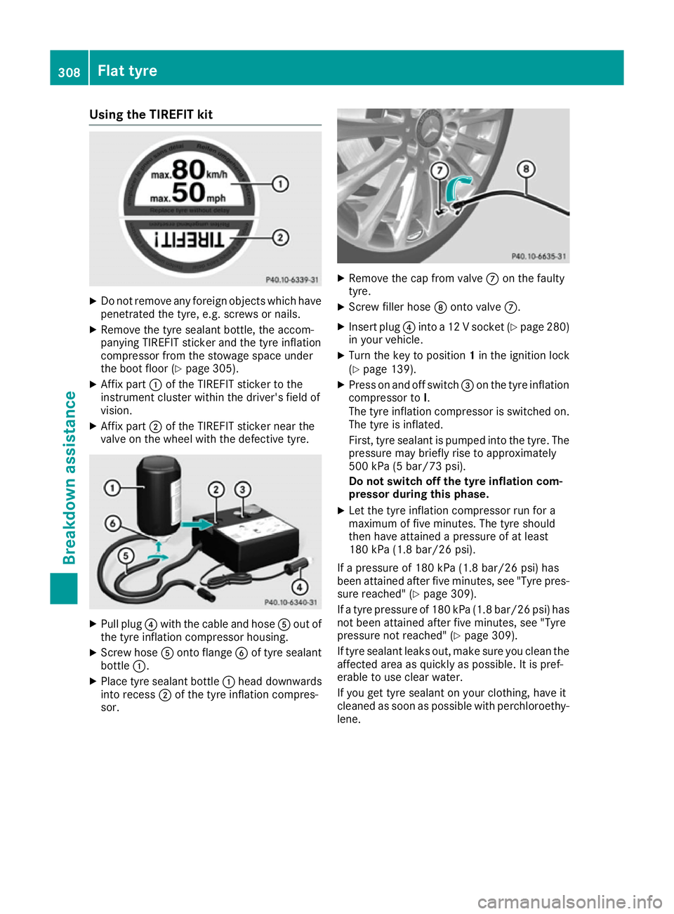
X Affix part :of the TIREFIT sticker to the
instrument cluster within the driver's field of
vision.
X Affix part ;of the TIREFIT sticker near the
valve on the wheel with the defective tyre. X
Pull plug ?with the cable and hose Aout of
the tyre inflation compressor housing.
X Screw hose Aonto flange Bof tyre sealant
bottle :.
X Place tyre sealant bottle :head downwards
into recess ;of the tyre inflation compres-
sor. X
Remove the cap from valve Con the faulty
tyre.
X Screw filler hose Donto valve C.
X Insert plug ?into a 12 V socket (Y page 280)
in your vehicle.
X Turn the key to position 1in the ignition lock
(Y page 139).
X Press on and off switch =on the tyre inflation
compressor to I.
The tyre inflation compressor is switched on.
The tyre is inflated.
First, tyre sealant is pumped into the tyre. The pressure may briefly rise to approximately
500 kPa (5 bar/73 psi).
Do not switch off the tyre inflation com-
pressor during this phase.
X Let the tyre inflation compressor run for a
maximum of five minutes. The tyre should
then have attained a pressure of at least
180 kPa (1.8 bar/26 psi).
If a pressure of 180 kPa (1.8 bar/26 psi) has
been attained after five minutes, see "Tyre pres-
sure reached" (Y page 309).
If a tyre pressure of 180 kPa (1.8 bar/26 psi) has not been attained after five minutes, see "Tyre
pressure not reached" (Y page 309).
If tyre sealant leaks out, make sure you clean the
affected area as quickly as possible. It is pref-
erable to use clear water.
If you get tyre sealant on your clothing, have it
cleaned as soon as possible with perchloroethy- lene. 308
Flat tyreBreakdown assistance
Page 312 of 349
Tyre pressure not reached
If a pressure of 180 kPa (1.8 bar/26 psi) has not
been attained after five minutes:
X Switch off the tyre inflation compressor.
X Unscrew the filler hose from the valve of the
faulty tyre.
Please note that tyre sealant may leak out
when unscrewing the filler hose.
X Very slowly drive forwards or reverse approx-
imately 10 m.
X Pump up the tyre again.
After a maximum of five minutes the tyre
pressure must be at least 180 kPa (1.8 bar/
26 psi). G
WARNING
If the required tyre pressure is not reached
after the specified time, the tyre is too badly
damaged. The tyre sealant cannot repair the
tyre in this instance. Damaged tyres and a tyre pressure that is too low can significantly
impair the vehicle's braking and driving char-
acteristics. There is a risk of accident.
Do not continue driving. Contact a qualified
specialist workshop.
Tyre pressure reached G
WARNING
A tyre temporarily sealed with tyre sealant
impairs the driving characteristics and is not
suitable for higher speeds. There is a risk of
accident.
You should therefore adapt your driving style
accordingly and drive carefully. Do not exceed the specified maximum speed with a tyre that
has been repaired using tyre sealant.
The maximum speed for a tyre sealed with tyre
sealant is 80 km/h. The upper part of the
TIREFIT sticker must be affixed to the instru-
ment cluster where it will be easily seen by the
driver.
! After use, excess tyre sealant may run out of
the filler hose. This could cause stains.
Therefore, place the tyre sealant bottle with
filler hose in the plastic bag which is con-
tained the TIREFIT kit. H
Environmental note
Have the used tyre sealant bottle disposed of professionally, e.g. at a qualified specialist
workshop.
If a tyre pressure of 180 kPa (1.8 bar/26 psi) has been attained after five minutes:
X Switch off the tyre inflation compressor.
X Unscrew the filler hose from the valve of the
faulty tyre.
X Stow the tyre sealant bottle, the tyre inflation
compressor and the warning triangle.
X Pull away immediately.
X Stop after driving for approximately ten
minutes and check the tyre pressure with the
tyre inflation compressor.
The tyre pressure must now be at least
130 kPa (1.3 bar/19 psi). G
WARNING
If the required tyre pressure is not reached
after driving for a short period, the tyre is too badly damaged. The tyre sealant cannot
repair the tyre in this instance. Damaged tyres and a tyre pressure that is too low can signif-
icantly impair the vehicle's braking and driv-
ing characteristics. There is a risk of accident.
Do not continue driving. Contact a qualified
specialist workshop.
i In your vehicle, you will find a sticker with
the Mercedes-Benz Service24h telephone
number, e.g. on the B-pillar on the driver's
side.
X Correct the tyre pressure if it is still at least
130 kPa (1.3 ba r/19 psi). See the tyre pres-
sure table on the fuel filler flap for values.
X To increase the tyre pressure: switch on
the tyre inflation compressor. Flat tyre
309Breakdown assistance Z
Page 318 of 349

X
Slide cover :of positive terminal ;in the direction of the arrow.
X Connect positive terminal ;on your vehicle to positive terminal =of donor battery Busing the
jump lead, always beginning with positive terminal ;on your own vehicle first.
X Start the engine of the donor vehicle and run it at idling speed.
X Connect negative terminal ?of donor battery Bto earth point Aof your vehicle using the jump
lead, connecting the jump lead to donor battery Bfirst.
X Start the engine.
X Before disconnecting the jump leads, let the engines run for several minutes.
X First, remove the jump leads from earth point Aand negative terminal ?, then from positive
clamp ;and positive terminal =. Begin each time at the contacts on your own vehicle first.
X Close cover :of positive clamp ;after removing the jump leads.
X Have the battery checked at a qualified specialist workshop.
Jump-starting is not considered to be a normal operating condition.
i Jump-starting cables and further information regarding jump-starting can be obtained at any
qualified specialist workshop. Towing away and tow-starting
Important safety notes
G
WARNING
Safety relevant functions are restricted or no
longer available if:
R the engine is not running
R the brake system or power steering is mal-
functioning
R there is a malfunction in the voltage supply
or the vehicle's electrical system
When your vehicle is towed away or towed
started, you may require considerably more
effort to steer and brake. There is a risk of an
accident.
In such cases use a rigid towing bar. Before
being towed away or tow started, make sure
the steering moves freely. G
WARNING
When towing or tow-starting another vehicle
and its weight is greater than the permissible gross weight of your vehicle, the:
R towing eye may be torn off
R car/trailer combination may swerve or
even overturn
There is a risk of an accident. When towing or tow-starting another vehicle,
its weight should not be greater than the per-
missible gross weight of your vehicle.
Details on the permissible gross vehicle weight
of your vehicle can be found on the vehicle iden-
tification plate (Y page 336).
! When COLLISION PREVENTION ASSIST
PLUS, DISTRONIC PLUS or the HOLD function is activated, the vehicle brakes automatically
in certain situations.
To avoid damage to the vehicle, deactivate
these systems in the following or similar sit-
uations:
R when towing away
R in a car wash
! Only secure the tow cable or tow bar to the
towing eyes or, if available, to the trailer tow
hitch. You could otherwise damage the vehi-
cle.
! Observe the following points when towing
with a tow rope:
R Secure the tow rope on the same side on
both vehicles.
R Make sure that the tow rope is not longer
than legally permitted. Mark the tow rope in
the middle, e.g. with a white cloth
(30 x 30 cm). This will make other road
users aware that a vehicle is being towed.
R Only secure the tow cable to the towing
eyes or, if available, to the trailer tow hitch. Towing away and tow-starting
315Breakdown assistance Z
Page 320 of 349
X
Remove cover :from the opening.
X Screw in the towing eye clockwise as far as it
will go and tighten it.
Vehicles with a trailer tow hitch do not have a
bracket at the back for the screw-in towing eye.
Connect the towbar to the trailer tow hitch
(Y page 209).
Removing the towing eye X
Loosen the towing eye and unscrew it.
X Position cover :on top of the bumper and
press it in at the bottom until it engages.
X Place the towing eye in the vehicle tool kit. Towing the vehicle with both axles on
the ground
It is important that you observe the safety
instructions when towing away your vehicle
(Y page 315).
X Turn the key to position 2in the ignition lock.
X When the vehicle is stationary, depress the
brake pedal and keep it depressed.
X Vehicles with manual transmission:
depress the clutch pedal fully and engage
neutral.
or X Vehicles with automatic transmission:
shift the transmission to position N.
X Release the brake pedal.
X Release the parking brake.
In order to signal a change of direction when
towing the vehicle with the hazard warning
lamps switched on, use the combination switch as usual. In this case, only the turn signals for
the desired direction flash. When you reset the
combination switch, the hazard warning lamps
start flashing again. Towing the vehicle away with the rear
axle raised
! Vehicles with automatic transmission must
not be towed with the rear axle raised. The
car/trailer combination may otherwise
swerve or even overturn.
! The ignition must be switched off if you are
towing the vehicle with the rear axle raised. Intervention by ESP
®
could otherwise dam-
age the brake system.
X Switch on the hazard warning lamps
(Y page 116).
X Move the front wheels to the straight-ahead
position.
X Turn the key in the ignition lock to position 0
and remove the key from the ignition lock.
X When leaving the vehicle, take the key with
you.
When towing your vehicle away with the rear
axle raised, it is important that you observe the
safety instructions (Y page 315). Transporting the vehicle
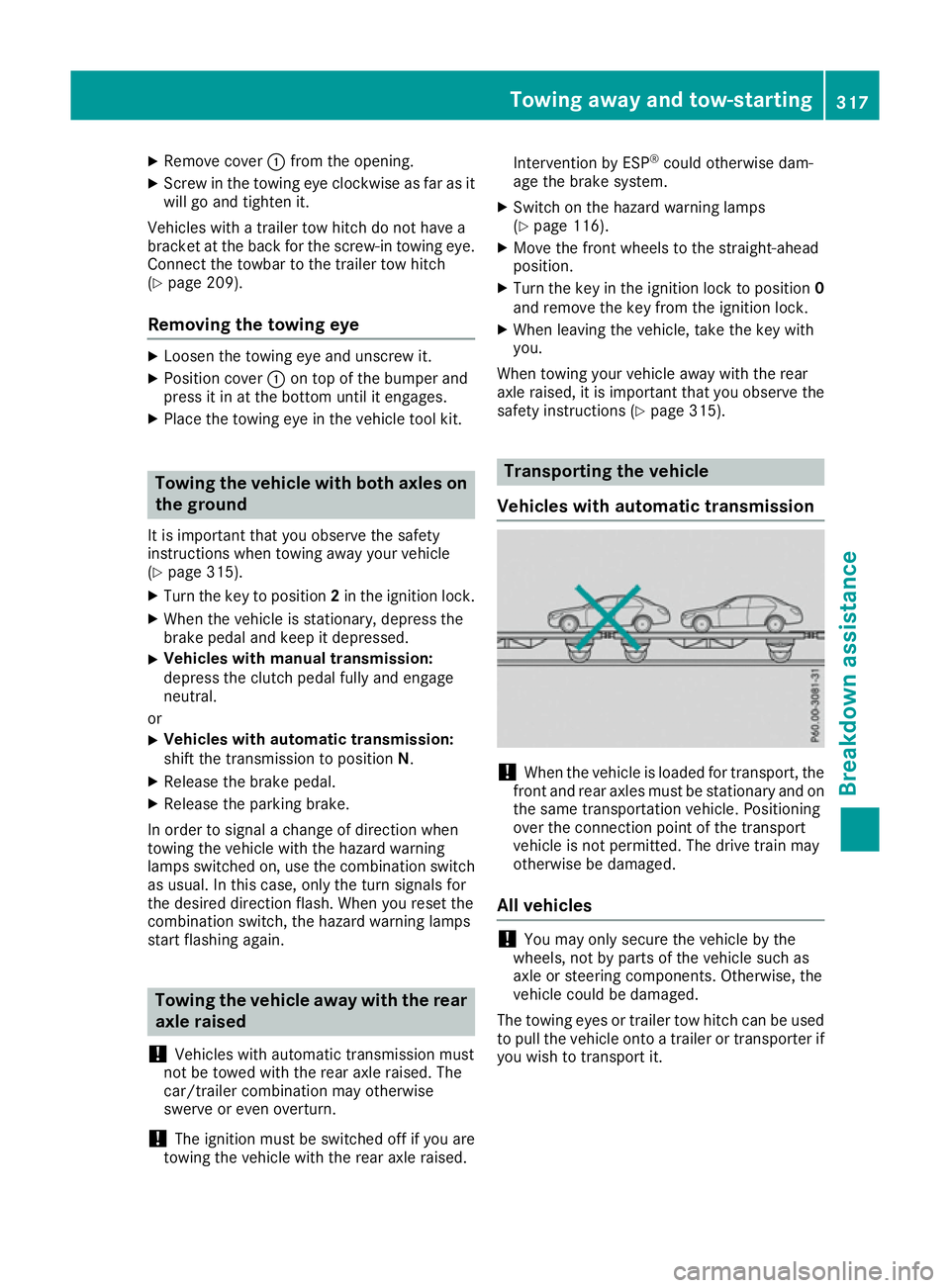
Vehicles with automatic transmission !
When the vehicle is loaded for transport, the
front and rear axles must be stationary and on
the same transportation vehicle. Positioning
over the connection point of the transport
vehicle is not permitted. The drive train may
otherwise be damaged.
All vehicles !
You may only secure the vehicle by the
wheels, not by parts of the vehicle such as
axle or steering components. Otherwise, the
vehicle could be damaged.
The towing eyes or trailer tow hitch can be used to pull the vehicle onto a trailer or transporter if
you wish to transport it. Towing away and tow-starting
317Breakdown assistance Z