2015 MERCEDES-BENZ B-Class ELECTRIC battery capacity
[x] Cancel search: battery capacityPage 8 of 338

Cargo tie down rings
.........................245
CD player/CD changer (on-board
computer) .......................................... 191
Center console
Lower section .................................. 35
Upper section .................................. 34
Central locking
Automatic locking (on-board com-
puter) ............................................. 198
Locking/unlocking (SmartKey) ....... .72
Changing bulbs
Cornering light function ................ .109
High-beam headlamps ................... 108
License plate lighting ..................... 110
Low-beam headlamps .................... 108
Parking lamps ................................ 108
Rear fog lamp ................................ 109
Reversing lamps ............................ 109
Standing lamps (front) ................... 108
Turn signals (front) ......................... 108
Charge level display .......................... 184
Charging
with RANGE PLUS .......................... 196
see Charging the high-voltage battery
Charging cable
Connecting ................................... .148
Controls ......................................... 146
Important safety notes .................. 146
Removing ....................................... 148
Storing .......................................... .146
Warming up ................................... 145
Charging the high-voltage battery
(important safety notes) ................... 140
Child
Restraint system .............................. 57
Child seat
Forward-facing restraint system ...... 61
LATCH-type (ISOFIX) child seat
anchors ............................................ 58
On the front-passenger sea t............ 60
Rearward-facing restraint system .... 60
Top Tether ....................................... 59
Child-proof locks
Important safety notes .................... 61
Rear doors ....................................... 62
Children
Special seat belt retractor ............... 57 Cigarette lighter
................................ 252
Cleaning
Mirror turn signal ........................... 275
Climate control
Automatic climate control (dual-
zone) .............................................. 117
Auxiliary climate control (on-
board computer) ............................ 196
Controlling automaticall y............... 120
Convenience opening/closing
(air-recirculation mode) ................. 123
Cooling with air dehumidification .. 118
Defrosting the window s................. 122
Defrosting the windshield .............. 121
General notes ................................ 116
Immediate pre-entry climate con-
trol ................................................. 125
Indicator lamp ................................ 120
Information about using auto-
matic climate control ..................... 117
Maximum cooling .......................... 122
Overview of systems ...................... 116
Pre-entry climate control at
departure time ............................... 125
Pre-entry climate control at time
of departure (on-board computer) .. 196 Pre-entry climate control via key ... 124
Pre-entry climate control via key
(on-board computer) ...................... 196
Problem with the rear window
defroster ........................................ 123
Problems with cooling with air
dehumidification ............................ 120
Refrigerant ..................................... 333
Refrigerant filling capacity ............. 334
Setting the air distribution ............. 120
Setting the air vents ...................... 126
Setting the airflow ......................... 121
Setting the temperature ................ 120
Switching air-recirculation mode
on/of f............................................ 123
Switching on/of f........................... 118
Switching the rear window
defroster on/of f............................ 122
Switching the ZONE function on/
off .................................................. 121
Cockpit
Overview .......................................... 30 6
Index
Page 9 of 338
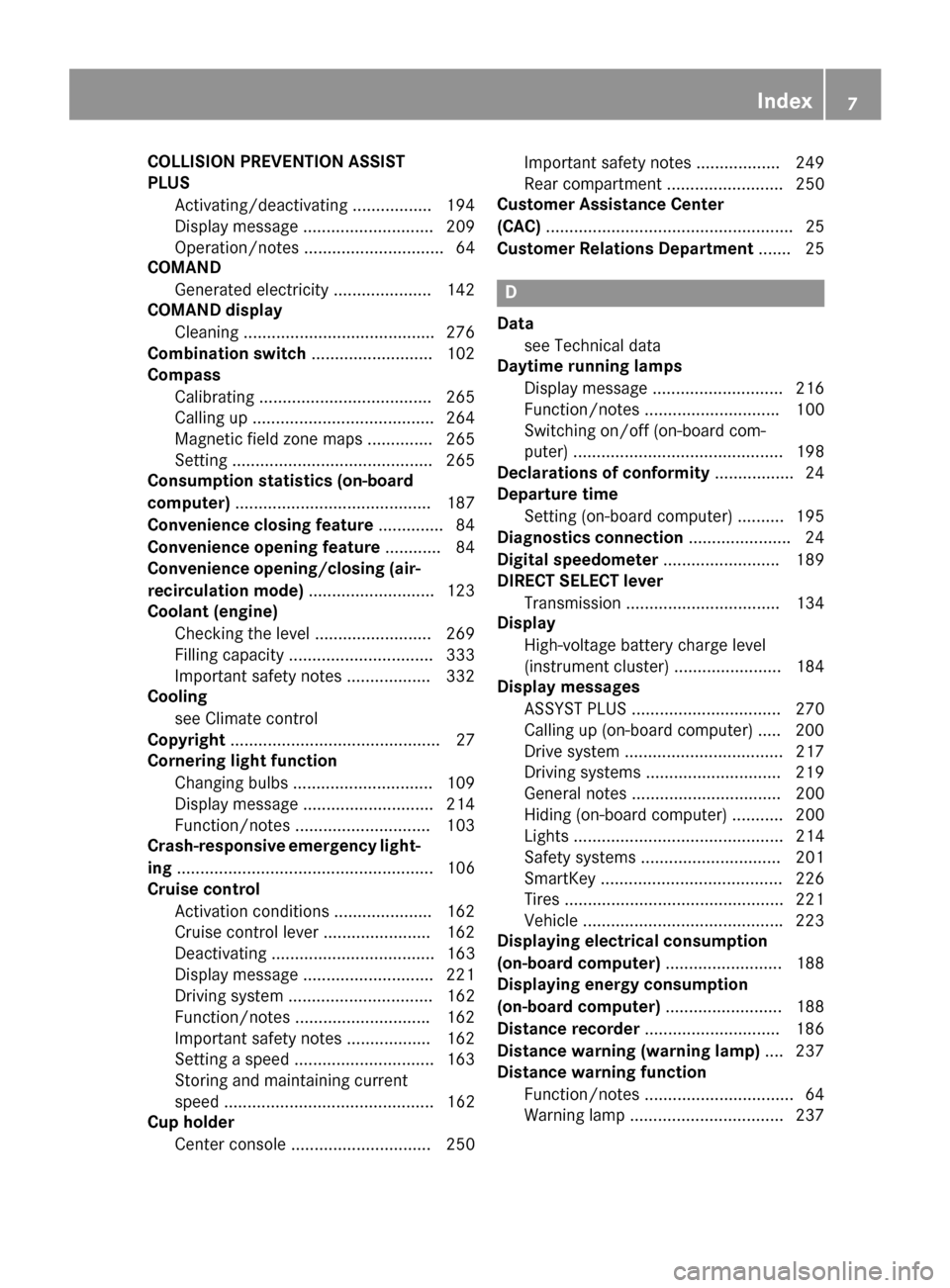
COLLISION PREVENTION ASSIST
PLUS
Activating/deactivating ................ .194
Display message ............................ 209
Operation/notes .............................. 64
COMAND
Generated electricity ..................... 142
COMAND display
Cleaning ......................................... 276
Combination switch .......................... 102
Compass
Calibrating ..................................... 265
Calling up ....................................... 264
Magnetic field zone maps .............. 265
Setting .......................................... .265
Consumption statistics (on-board
computer) .......................................... 187
Convenience closing feature .............. 84
Convenience opening feature ............ 84
Convenience opening/closing (air-
recirculation mode) ........................... 123
Coolant (engine)
Checking the level ......................... 269
Filling capacity ............................... 333
Important safety notes .................. 332
Cooling
see Climate control
Copyright ............................................. 27
Cornering light function
Changing bulbs .............................. 109
Display message ............................ 214
Function/notes ............................ .103
Crash-responsive emergency light-
ing ....................................................... 106
Cruise control
Activation conditions ..................... 162
Cruise control lever ....................... 162
Deactivating ................................... 163
Display message ............................ 221
Driving system ............................... 162
Function/notes ............................ .162
Important safety notes .................. 162
Setting a speed .............................. 163
Storing and maintaining current
speed ............................................. 162
Cup holder
Center console .............................. 250 Important safety notes .................. 249
Rear compartment ......................... 250
Customer Assistance Center
(CAC) ..................................................... 25
Customer Relations Department ....... 25 D
Data see Technical data
Daytime running lamps
Display message ............................ 216
Function/notes ............................ .100
Switching on/off (on-board com-
puter) ............................................. 198
Declarations of conformity ................. 24
Departure time
Setting (on-board computer) .......... 195
Diagnostics connection ......................24
Digital speedometer .........................189
DIRECT SELECT lever
Transmission ................................. 134
Display
High-voltage battery charge level
(instrument cluster) ....................... 184
Display messages
ASSYST PLUS ................................ 270
Calling up (on-board computer) ..... 200
Drive system .................................. 217
Driving systems ............................ .219
General notes ................................ 200
Hiding (on-board computer) ........... 200
Lights ............................................. 214
Safety systems .............................. 201
SmartKey ....................................... 226
Tires ............................................... 221
Vehicle .......................................... .223
Displaying electrical consumption
(on-board computer) ......................... 188
Displaying energy consumption
(on-board computer) ......................... 188
Distance recorder .............................186
Distance warning (warning lamp) .... 237
Distance warning function
Function/notes ................................ 64
Warning lamp ................................. 237 Index
7
Page 220 of 338
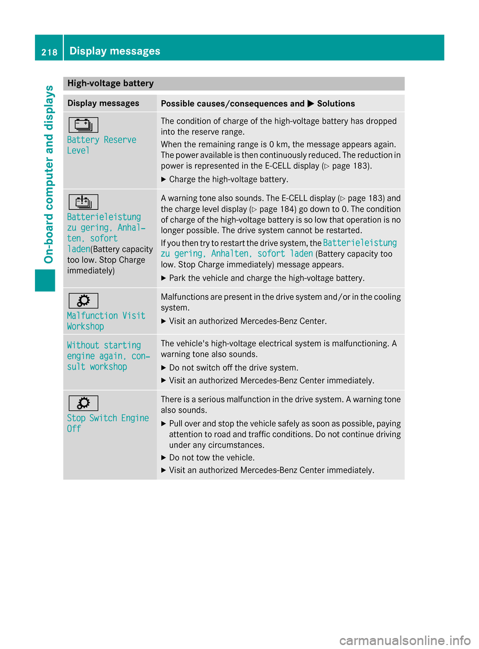
High-voltage battery
Display messages
Possible causes/consequences and
M
MSolutions Ý
Battery Reserve Battery Reserve
Level Level The condition of charge of the high-voltage battery has dropped
into the reserve range.
When the remaining range is 0 km, the message appears again.
The power available is then continuously reduced. The reduction in power is represented in the E-CELL display (Y page 183).
X Charge the high-voltage battery. Û
Batterieleistung Batterieleistung
zu gering, Anhal‐ zu gering, Anhal‐
ten, sofort ten, sofort
laden laden(Battery capacity
too low. Stop Charge
immediately) A warning tone also sounds. The E
‑CELL display (Ypage 183) and
the charge level display (Y page 184) go down to 0. The condition
of charge of the high-voltage battery is so low that operation is no
longer possible. The drive system cannot be restarted.
If you then try to restart the drive system, the Batterieleistung Batterieleistung
zu gering, Anhalten, sofort laden
zu gering, Anhalten, sofort laden (Battery capacity too
low. Stop Charge immediately) message appears.
X Park the vehicle and charge the high-voltage battery. ì
Malfunction Visit Malfunction Visit
Workshop Workshop Malfunctions are present in the drive system and/or in the cooling
system.
X Visit an authorized Mercedes-Benz Center. Without starting
Without starting
engine again, con‐ engine again, con‐
sult workshop sult workshop The vehicle's high-voltage electrical system is malfunctioning. A
warning tone also sounds.
X Do not switch off the drive system.
X Visit an authorized Mercedes-Benz Center immediately. ì
Stop Stop
Switch
Switch Engine
Engine
Off
Off There is a serious malfunction in the drive system. A warning tone
also sounds.
X Pull over and stop the vehicle safely as soon as possible, paying
attention to road and traffic conditions. Do not continue driving
under any circumstances.
X Do not tow the vehicle.
X Visit an authorized Mercedes-Benz Center immediately. 218
Display messagesOn-board computer and displays
Page 293 of 338
The drive system cannot be started if the 12 V battery is discharged. This is not dependent on
whether the high-voltage battery is charged or not. The vehicle cannot be jump-started if the
high-voltage battery is discharged. The high-voltage battery must be charged first.
The drive system can be started using another vehicle. R Only use batteries with an equal nominal voltage (12 volts).
R Make sure that the battery of the donor vehicle does not have a significantly lower capacity
than the discharged battery.
R Use jumper cables with a sufficient cross-section and insulated terminal clamps from a
qualified specialist workshop, e.g. an authorized Mercedes-Benz Center.
R Make sure that the two vehicles do not touch.
R Route the jumper cables so that they cannot be caught by rotating components in the engine
compartment.
R Do not disconnect the discharged battery from the vehicle's electrical system. X
Switch off the engine of both vehicles.
X Shift the transmission to position P.
X Switch off all electrical consumers.
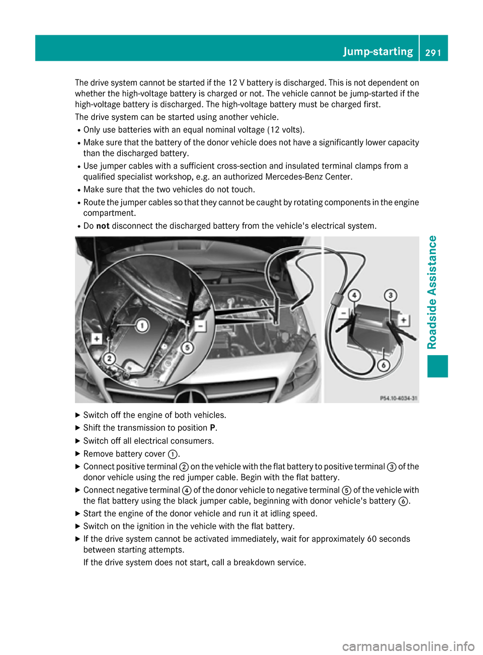
X Remove battery cover :.
X Connect positive terminal ;on the vehicle with the flat battery to positive terminal =of the
donor vehicle using the red jumper cable. Begin with the flat battery.
X Connect negative terminal ?of the donor vehicle to negative terminal Aof the vehicle with
the flat battery using the black jumper cable, beginning with donor vehicle's battery B.
X Start the engine of the donor vehicle and run it at idling speed.
X Switch on the ignition in the vehicle with the flat battery.
X If the drive system cannot be activated immediately, wait for approximately 60 seconds
between starting attempts.
If the drive system does not start, call a breakdown service. Jump-starting
291Roadside Assistance Z
Page 322 of 338
Curb weight
The weight of a vehicle with standard equip-
ment including the maximum capacity of fuel, oil and coolant. It also includes the air-condi-
tioning system and optional equipment if
these are installed in the vehicle, but does not include passengers or luggage.
Maximum load rating
The maximum load rating is the maximum
permissible weight in kilograms or lbs for
which a tire is approved.
Maximum permissible tire pressure
Maximum permissible tire pressure for one
tire.
Maximum load on one tire
Maximum load on one tire. This is calculated
by dividing the maximum axle load of one axle by two.
PSI (pounds per square inch)
A standard unit of measure for tire pressure.
Aspect ratio
Relationship between tire height and tire
width in percent.
Tire pressure
This is pressure inside the tire applying an
outward force to each square inch of the tire's
surface. The tire pressure is specified in
pounds per square inch (psi), in kilopascal
(kPa) or in bar. The tire pressure should only
be corrected when the tires are cold.
Cold tire pressure
The tires are cold:
R if the vehicle has been parked without
direct sunlight on the tires for at least three
hours and
R if the vehicle has not been driven further
than 1 mile (1.6 km) Tread
The part of the tire that comes into contact
with the road.
Bead
The tire bead ensures that the tire sits
securely on the wheel. There are several steel
wires in the bead to prevent the tire from
coming loose from the wheel rim.
Sidewall
The part of the tire between the tread and the bead.
Weight of optional extras
The combined weight of those optional extras
that weigh more than the replaced standard
parts and more than 2.3 kg (5 lbs). These
optional extras, such as high-performance
brakes, level control, a roof rack or a high-
performance battery, are not included in the
curb weight and the weight of the accesso-
ries.
TIN (Tire Identification Number)
This is a unique identifier which can be used
by a tire manufacturer to identify tires, for
example for a product recall, and thus identify the purchasers. The TIN is made up of the
manufacturer's identity code, tire size, tire
type code and the manufacturing date.
Load bearing index
The load bearing index (also load index) is a
code that contains the maximum load bearing
capacity of a tire.
Traction
Traction is the result of friction between the
tires and the road surface.
Treadwear indicators
Narrow bars (tread wear bars) that are dis-
tributed over the tire tread. If the tire tread is level with the bars, the wear limit of áin
(1.6 mm) has been reached. 320
All about wheels and tiresWheels and tires
Page 325 of 338
tion the jack correctly, the vehicle may be
damaged.
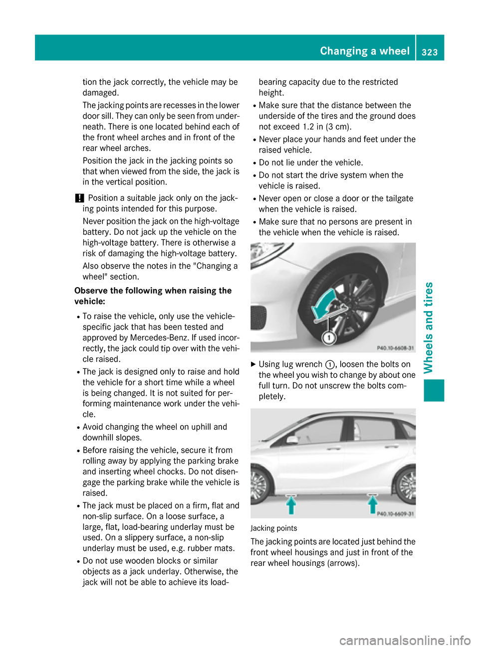
The jacking points are recesses in the lower
door sill. They can only be seen from under- neath. There is one located behind each of
the front wheel arches and in front of the
rear wheel arches.
Position the jack in the jacking points so
that when viewed from the side, the jack is
in the vertical position.
! Position a suitable jack only on the jack-
ing points intended for this purpose.
Never position the jack on the high-voltage
battery. Do not jack up the vehicle on the
high-voltage battery. There is otherwise a
risk of damaging the high-voltage battery.
Also observe the notes in the "Changing a
wheel" section.
Observe the following when raising the
vehicle:
R To raise the vehicle, only use the vehicle-
specific jack that has been tested and
approved by Mercedes-Benz. If used incor-
rectly, the jack could tip over with the vehi-
cle raised.
R The jack is designed only to raise and hold
the vehicle for a short time while a wheel
is being changed. It is not suited for per-
forming maintenance work under the vehi- cle.
R Avoid changing the wheel on uphill and
downhill slopes.
R Before raising the vehicle, secure it from
rolling away by applying the parking brake
and inserting wheel chocks. Do not disen-
gage the parking brake while the vehicle is
raised.
R The jack must be placed on a firm, flat and
non-slip surface. On a loose surface, a
large, flat, load-bearing underlay must be
used. On a slippery surface, a non-slip
underlay must be used, e.g. rubber mats.
R Do not use wooden blocks or similar
objects as a jack underlay. Otherwise, the
jack will not be able to achieve its load- bearing capacity due to the restricted
height.
R Make sure that the distance between the
underside of the tires and the ground does
not exceed 1.2 in (3 cm).
R Never place your hands and feet under the
raised vehicle.
R Do not lie under the vehicle.
R Do not start the drive system when the
vehicle is raised.
R Never open or close a door or the tailgate
when the vehicle is raised.
R Make sure that no persons are present in
the vehicle when the vehicle is raised. X
Using lug wrench :, loosen the bolts on
the wheel you wish to change by about one full turn. Do not unscrew the bolts com-
pletely. Jacking points
The jacking points are located just behind the front wheel housings and just in front of the
rear wheel housings (arrows). Changing a
wheel
323Wheels an d tires Z