2015 MERCEDES-BENZ B-Class ELECTRIC stop start
[x] Cancel search: stop startPage 296 of 338

Installing/removing the towing eye
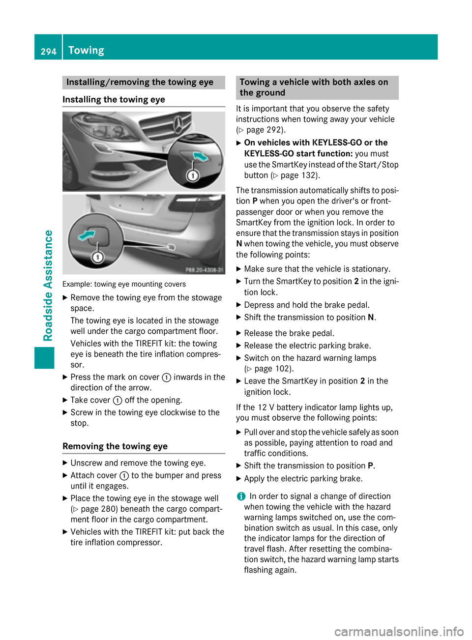
Installing the towing eye Example: towing eye mounting covers
X Remove the towing eye from the stowage
space.
The towing eye is located in the stowage
well under the cargo compartment floor.
Vehicles with the TIREFIT kit: the towing
eye is beneath the tire inflation compres-
sor.
X Press the mark on cover :inwards in the
direction of the arrow.
X Take cover :off the opening.
X Screw in the towing eye clockwise to the
stop.
Removing the towing eye X
Unscrew and remove the towing eye.
X Attach cover :to the bumper and press
until it engages.
X Place the towing eye in the stowage well
(Y page 280) beneath the cargo compart-
ment floor in the cargo compartment.
X Vehicles with the TIREFIT kit: put back the
tire inflation compressor. Towing a vehicle with both axles on
the ground
It is important that you observe the safety
instructions when towing away your vehicle
(Y page 292).
X On vehicles with KEYLESS-GO or the
KEYLESS-GO start function: you must
use the SmartKey instead of the Start/Stop
button (Y page 132).
The transmission automatically shifts to posi- tion Pwhen you open the driver's or front-
passenger door or when you remove the
SmartKey from the ignition lock. In order to
ensure that the transmission stays in position N when towing the vehicle, you must observe
the following points:
X Make sure that the vehicle is stationary.
X Turn the SmartKey to position 2in the igni-
tion lock.
X Depress and hold the brake pedal.
X Shift the transmission to position N.
X Release the brake pedal.
X Release the electric parking brake.
X Switch on the hazard warning lamps
(Y page 102).
X Leave the SmartKey in position 2in the
ignition lock.
If the 12 V battery indicator lamp lights up,
you must observe the following points:
X Pull over and stop the vehicle safely as soon
as possible, paying attention to road and
traffic conditions.
X Shift the transmission to position P.
X Apply the electric parking brake.
i In order to signal a change of direction
when towing the vehicle with the hazard
warning lamps switched on, use the com-
bination switch as usual. In this case, only
the indicator lamps for the direction of
travel flash. After resetting the combina-
tion switch, the hazard warning lamp starts
flashing again. 294
TowingRoadside Assistance
Page 297 of 338

Towing the vehicle with the front axle
raised
When towing your vehicle with the rear axle
raised, it is important that you observe the
safety instructions (Y page 292).
! The ignition must be switched off if the
vehicle is being towed with the front axle
raised. Otherwise, ESP ®
may intervene and
damage the brake system.
X On vehicles with KEYLESS-GO or the
KEYLESS-GO start function: you must
use the SmartKey instead of the Start/Stop button (Y page 132).
X Make sure that the vehicle is stationary.
X Turn the SmartKey to position 2in the igni-
tion lock.
X When the vehicle is stationary, depress the
brake pedal and keep it depressed.
X Shift the transmission to position P.
X Release the brake pedal.
X Release the electric parking brake.
X Switch off the automatic locking
(Y page 198).
X Switch on the hazard warning lamps
(Y page 102).
X Turn the SmartKey in the ignition lock to
position 0and leave the SmartKey in the
ignition lock. Towing the vehicle with the rear axle
raised
When towing your vehicle with the rear axle
raised, it is important that you observe the
safety instructions (Y page 292).
! The ignition must be switched off if you
are towing the vehicle with the rear axle
raised. Intervention by ESP ®
could other-
wise damage the brake system. The transmission automatically shifts to posi-
tion Pwhen you open the driver's or front-
passenger door or when you remove the
SmartKey from the ignition lock. In order to
ensure that the transmission stays in position N when towing the vehicle, you must observe
the following points:
X On vehicles with KEYLESS-GO or the
KEYLESS-GO start function: you must
use the SmartKey instead of the Start/Stop
button (Y page 132).
X Make sure that the vehicle is stationary.
X Turn the SmartKey to position 2in the igni-
tion lock.
X Depress and hold the brake pedal.
X Shift the transmission to position N.
X Release the brake pedal.
X Apply the electric parking brake.
X Switch off the automatic locking
(Y page 198).
X Bring the front wheels into the straight-
ahead position.
X Switch on the hazard warning lamps
(Y page 102).
X Turn the SmartKey in the ignition lock to
position 0and leave the SmartKey in the
ignition lock. Transporting the vehicle
! You may only secure the vehicle by the
wheels, not by parts of the vehicle such as
axle or steering components. Otherwise,
the vehicle could be damaged.
X Turn the SmartKey to position 2in the igni-
tion lock (Y page 131).
X Shift the transmission to position N.
As soon as the vehicle has been loaded:
X Prevent the vehicle from rolling away by
applying the electric parking brake.
X Shift the transmission to position P. Towing
295Roadside Assistance Z
Page 298 of 338

X
Turn the SmartKey to position 0in the igni-
tion lock and remove it.
X Secure the vehicle.
The towing eye can be used to pull the vehicle
onto a trailer or transporter for transporting
purposes. Fuses
Important safety notes
G
WARNING
If you manipulate or bridge a faulty fuse or if
you replace it with a fuse with a higher amper- age, the electric cables could be overloaded.
This could result in a fire. There is a risk of an
accident and injury.
Always replace faulty fuses with the specified
new fuses having the correct amperage.
Blown fuses must be replaced with fuses of
the same rating, which you can recognize by
the color and value. The fuse ratings are listed in the fuse allocation chart.
If a newly inserted fuse also blows, have the
cause traced and rectified at a qualified spe-
cialist workshop, e.g. an authorized
Mercedes-Benz Center.
! Only use fuses that have been approved
for Mercedes-Benz vehicles and which
have the correct fuse rating for the system
concerned. Only use fuses marked with an "S". Otherwise, components or systems
could be damaged.
The fuses in your vehicle serve to close down faulty circuits. If a fuse blows, all the compo-
nents on the circuit and their functions stop
operating.
Blown fuses must be replaced with fuses of
the same rating, which you can recognize by
the color and value. The fuse ratings are listed in the fuse allocation chart.
If a newly inserted fuse also blows, have the
cause traced and rectified at a qualified spe- cialist workshop, e.g. an authorized
Mercedes-Benz Center. Before changing a fuse
X Secure the vehicle against rolling away
(Y page 153).
X Switch off all electrical consumers.
X Vehicles without KEYLESS-GO: remove
the SmartKey from the ignition lock.
X Vehicles with KEYLESS-GO start-func-
tion or KEYLESS-GO: open the driver's
door.
The on-board electronics now have status
0. This is the same as the SmartKey having
been removed.
The fuses are located in various fuse boxes:
R Fuse box in the engine compartment on the
left-hand side of the vehicle, when viewed
in the direction of travel
R Fuse box in the front-passenger footwell
The fuse allocation chart is on the fuse box in
the front-passenger footwell (Y page 297). Fuse box in the engine compartment
G
WARNING
When the hood is open and the windshield
wipers are set in motion, you can be injured by the wiper linkage. There is a risk of injury.
Always switch off the windshield wipers and
the ignition before opening the hood.
! Make sure that no moisture can enter the
fuse box when the cover is open.
! When closing the cover, make sure that it
is lying correctly on the fuse box. Moisture
seeping in or dirt could otherwise impair
the operation of the fuses. 296
FusesRoadside Assistance
Page 324 of 338

X
Vehicles with KEYLESS-GO start-func-
tion or KEYLESS-GO: open the driver's
door.
The on-board electronics now have status
0. This is the same as the SmartKey having been removed.
X Vehicles with KEYLESS-GO start-func-
tion or KEYLESS-GO: remove the Start/
Stop button from the ignition lock
(Y page 131).
X If included in the vehicle equipment,
remove the tire-change tool kit from the
vehicle.
X Safeguard the vehicle against rolling away
(Y page 153).
Securing the vehicle to prevent it from
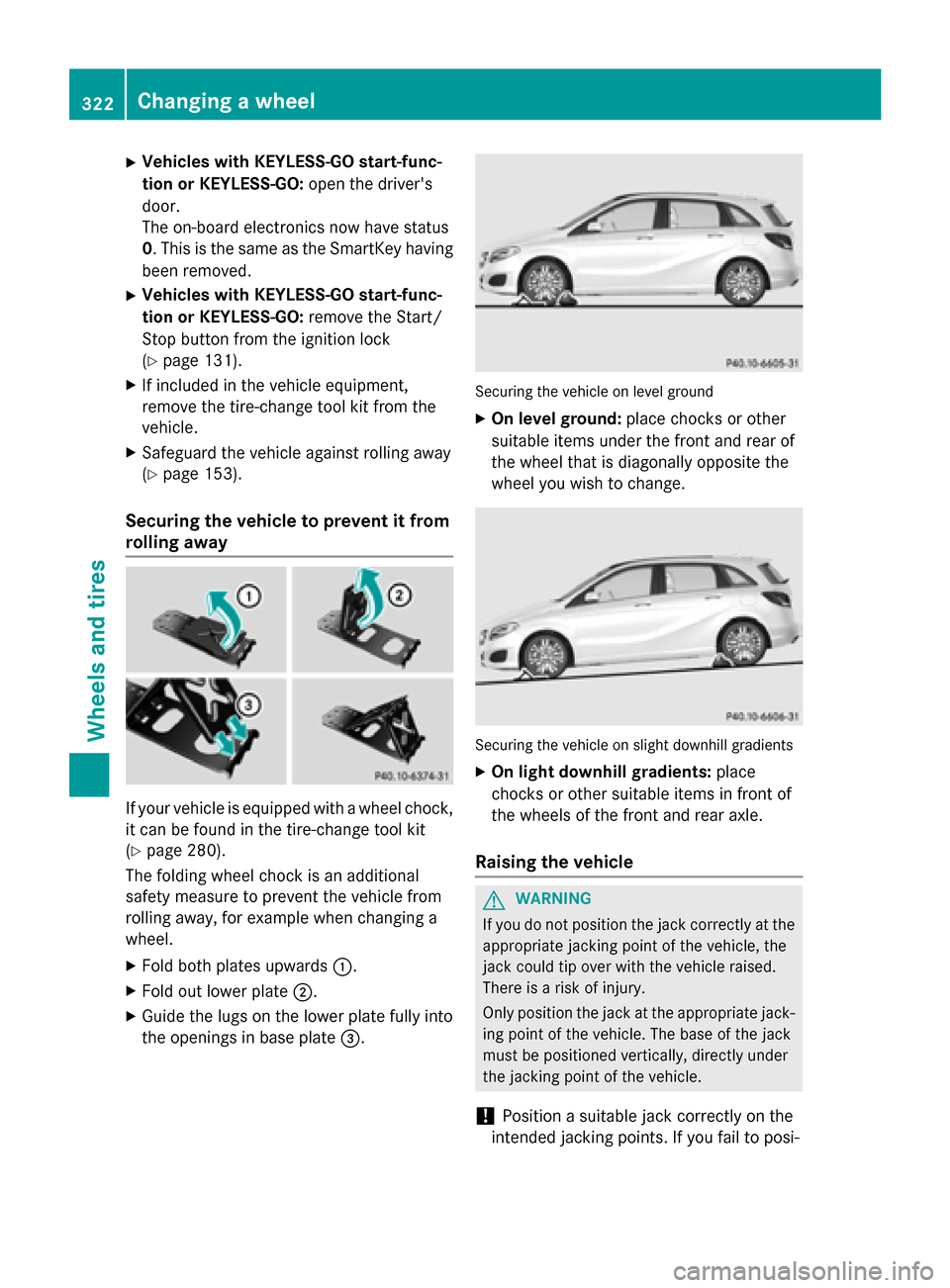
rolling away If your vehicle is equipped with a wheel chock,
it can be found in the tire-change tool kit
(Y page 280).
The folding wheel chock is an additional
safety measure to prevent the vehicle from
rolling away, for example when changing a
wheel.
X Fold both plates upwards :.
X Fold out lower plate ;.
X Guide the lugs on the lower plate fully into
the openings in base plate =. Securing the vehicle on level ground
X On level ground: place chocks or other
suitable items under the front and rear of
the wheel that is diagonally opposite the
wheel you wish to change. Securing the vehicle on slight downhill gradients
X On light downhill gradients: place
chocks or other suitable items in front of
the wheels of the front and rear axle.
Raising the vehicle G
WARNING
If you do not position the jack correctly at the appropriate jacking point of the vehicle, the
jack could tip over with the vehicle raised.
There is a risk of injury.
Only position the jack at the appropriate jack-
ing point of the vehicle. The base of the jack
must be positioned vertically, directly under
the jacking point of the vehicle.
! Position a suitable jack correctly on the
intended jacking points. If you fail to posi- 322
Changing a wheelWheels and tires