2015 MERCEDES-BENZ B-Class ELECTRIC warning light
[x] Cancel search: warning lightPage 108 of 338
Crash-responsive emergency lighting
The interior lighting is activated automatically
if the vehicle is involved in an accident.
X To switch off the crash-responsive
emergency lighting: press the hazard
warning lamp button.
or X Lock and then unlock the vehicle using the
SmartKey. Replacing bulbs
Important safety notes
Xenon bulbs G
DANGER
Xenon bulbs carry a high voltage. You can get an electric shock if you remove the cover of
the Xenon bulb and touch the electrical con-
tacts. There is a risk of fatal injury.
Never touch the parts or the electrical con-
tacts of the Xenon bulb. Always have work on
the Xenon bulbs carried out at a qualified spe-
cialist workshop.
If your vehicle is equipped with Xenon bulbs,
you can recognize this by the following: the
cone of light from the Xenon bulbs moves
from the top to the bottom and back again
when you start the drive system. For this to be
observed, the lights must be switched on
before the drive system is started.
Bulbs and lamps are an important aspect of
vehicle safety. You must therefore make sure that these function correctly at all times.
Have the headlamp setting checked regularly.
Other bulbs G
WARNING
Bulbs, lamps and connectors can get very hot when operating. If you change a bulb, you
could burn yourself on these components.
There is a risk of injury.
Allow these components to cool down before changing a bulb. Do not use a bulb that has been dropped or if
its glass tube has been scratched.
The bulb may explode if:
R you touch it
R it is hot
R you drop it
R you scratch it
Only operate bulbs in enclosed lamps
designed for that purpose. Only install spare
bulbs of the same type and the specified volt- age.
Marks on the glass tube reduce the service
life of the bulbs. Do not touch the glass tube
with your bare hands. If necessary, clean the
glass tube when cold with alcohol or spirit and
rub it off with a lint-free cloth.
Protect bulbs from moisture during opera-
tion. Do not allow bulbs to come into contact
with liquids.
There are bulbs other than the Xenon bulbs
that you cannot replace. Replace only the
bulbs listed (Y page 106). Have the bulbs that
you cannot replace yourself changed at a
qualified specialist workshop.
If you require assistance changing bulbs, con- sult a qualified specialist workshop.
If the new bulb still does not light up, consult
a qualified specialist workshop.
Bulbs and lamps are an important aspect of
vehicle safety. You must therefore make sure that these function correctly at all times.
Have the headlamp setting checked regularly. Overview: changing bulbs/bulb types
You can change the following bulbs. The bulb type can be found in the legend. 106
Replacing bulbsLights and windshield wipers
Page 114 of 338
4
0Switches off intermittent wiping
5 ô Wipes with washer fluid
X Switch on the ignition.
X Turn switch :on the combination switch
to the corresponding position.
When the rear window wiper is switched on,
the è symbol appears in the assistance
graphic in the instrument cluster. Further
information on the assistance graphic
(Y page 193). Replacing the wiper blades
Important safety notes G
WARNING
If the windshield wipers begin to move while
you are changing the wiper blades, you could be trapped by the wiper arm. There is a risk of
injury.
Always switch off the windshield wipers and
ignition before changing the wiper blades.
! To avoid damaging the wiper blades,
make sure that you touch only the wiper
arm of the wiper.
! Never open the hood/tailgate if a wiper
arm has been folded away from the wind-
shield/rear window.
Never fold a windshield wiper arm without a
wiper blade back onto the windshield/rear window.
Hold the windshield wiper arm firmly whenyou change the wiper blade. If you release
the wiper arm without a wiper blade and it
falls onto the windshield/rear window, the
windshield/rear window may be damaged
by the force of the impact.
Mercedes-Benz recommends that you have the wiper blades changed at a qualified
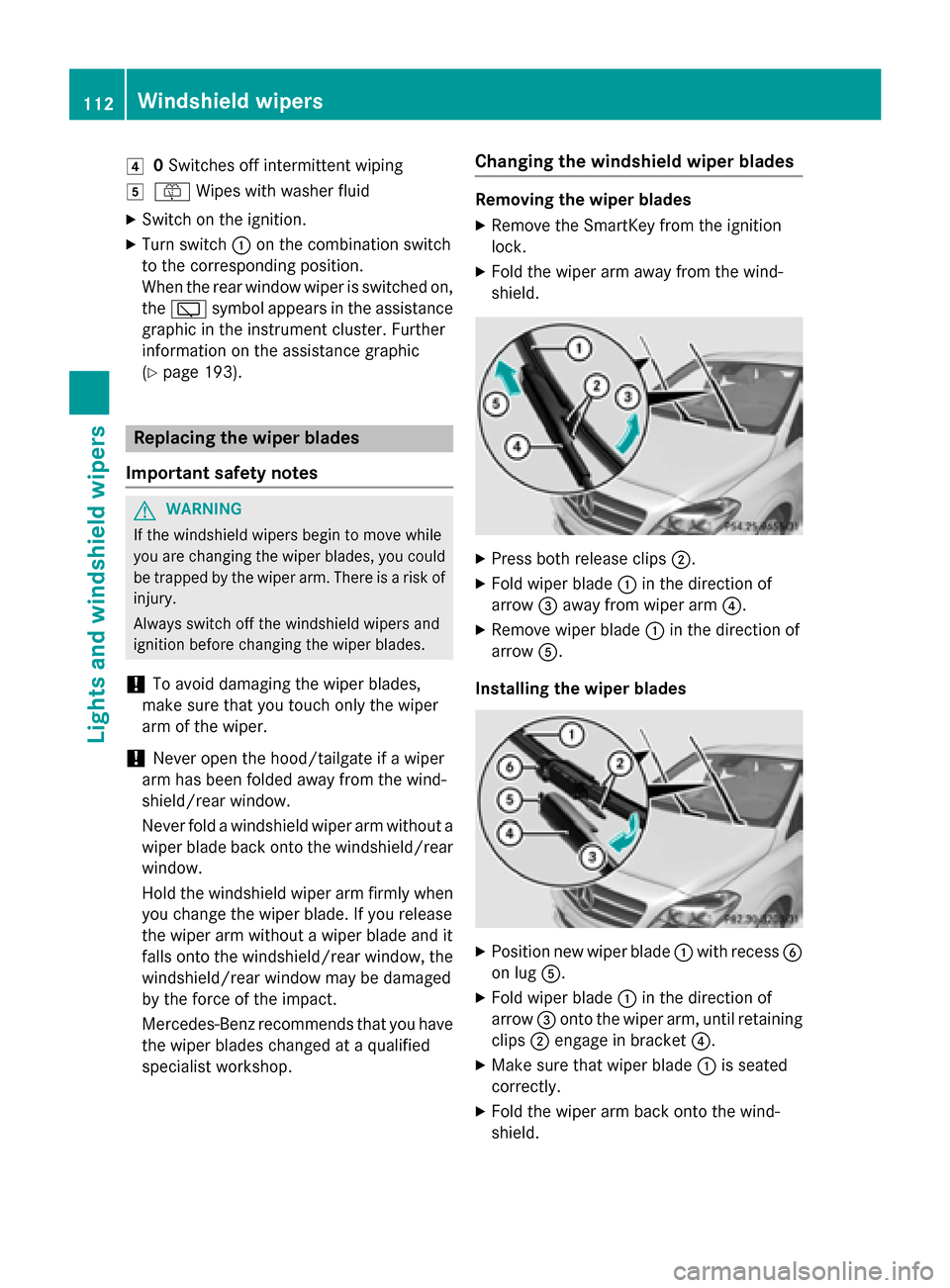
specialist workshop. Changing the windshield wiper blades Removing the wiper blades
X Remove the SmartKey from the ignition
lock.
X Fold the wiper arm away from the wind-
shield. X
Press both release clips ;.
X Fold wiper blade :in the direction of
arrow =away from wiper arm ?.
X Remove wiper blade :in the direction of
arrow A.
Installing the wiper blades X
Position new wiper blade :with recess B
on lug A.
X Fold wiper blade :in the direction of
arrow =onto the wiper arm, until retaining
clips ;engage in bracket ?.
X Make sure that wiper blade :is seated
correctly.
X Fold the wiper arm back onto the wind-
shield. 112
Windshield wipersLights and windshield wipers
Page 125 of 338
Problems with the rear window defroster
Problem
Possible causes/consequences and
M
MSolutions The rear window
defroster has deactiva-
ted prematurely or can-
not be activated. The battery has not been sufficiently charged.
X Switch off any consumers that are not required, e.g. reading
lamps, interior lighting or the seat heating.
When the battery is sufficiently charged, the rear window
defroster can be activated again. Activating/deactivating air-recircula-
tion mode
General notes You can deactivate the flow of fresh air if
unpleasant odors are entering the vehicle
from outside. The air already inside the vehi-
cle will then be recirculated.
If you switch on air-recirculation mode, the
windows can fog up more quickly, in particu-
lar at low temperatures. Only use air-recircu-
lation mode briefly to prevent the windows
from fogging up.
Switching on/off X
Turn the SmartKey to position 2in the igni-
tion lock (Y page 131).
X To activate: press theebutton.
The indicator lamp in the ebutton lights
up.
Air-recirculation mode switches on automat-
ically:
R at high outside temperatures
R at high levels of pollution
When air-recirculation mode is activated
automatically, the indicator lamp in the e
button is not lit. Outside air is added after
about 30 minutes.
X To deactivate: press theebutton.
The indicator lamp in the ebutton goes
out. i
Air-recirculation mode deactivates auto-
matically:
R after approximately five minutes at out-
side temperatures below approximately
45 ‡ (7 †)
R after approximately five minutes if the
"Cooling with air dehumidification" func-
tion is deactivated
R after approximately 30 minutes at out-
side temperatures above approximately
45 ‡ (7 †) if the cooling with air dehu-
midification function is activated Convenience opening/closing using
the air-recirculation button
G
WARNING
When using the convenience closing feature,
parts of the body could be trapped in the clos- ing area when a side window is being closed. There is a risk of injury.
Observe the complete closing procedure
when the convenience closing feature is oper-
ating. Make sure that no body parts are in
close proximity during the closing procedure. G
WARNING
During convenience opening parts of the body could be drawn in or become trapped
between the side window and window frame.
There is a risk of injury.
Make sure that nobody touches the side win-
dow during the opening procedure. If some-
one becomes trapped, press the Wswitch Operating the climate control systems
123Climate control
Z
Page 128 of 338
To activate/deactivate "Immediate pre-
entry climate control"
X Press button :in the center console.
The blue or red indicator lamp in the button
lights up or goes out.
The colors of the indicator lamps in the button have the following meanings:
Re dH eating activated
Blue Cooling activated
Yellow Pre-entry climate control at depar- ture is preselected Air vents
Important safety notes
G
WARNING
Very hot or very cold air can flow from the air vents. This could result in burns or frostbite in the immediate vicinity of the air vents. There
is a risk of injury.
Make sure that all vehicle occupants always
maintain a sufficient distance to the air out-
lets. If necessary, redirect the airflow to
another area of the vehicle interior.
In order to ensure the direct flow of fresh air
through the air vents into the vehicle interior,
please observe the following notes:
R keep the air inlet between the windshield
and the hood free of blockages, such as ice, snow or leaves.
R never cover the air vents or air intake grilles
in the vehicle interior.
i You can move the adjusters for the air
vents vertically or horizontally to set the
direction of the airflow.
i For optimal climate control in the vehicle,
open the air vents completely and set the
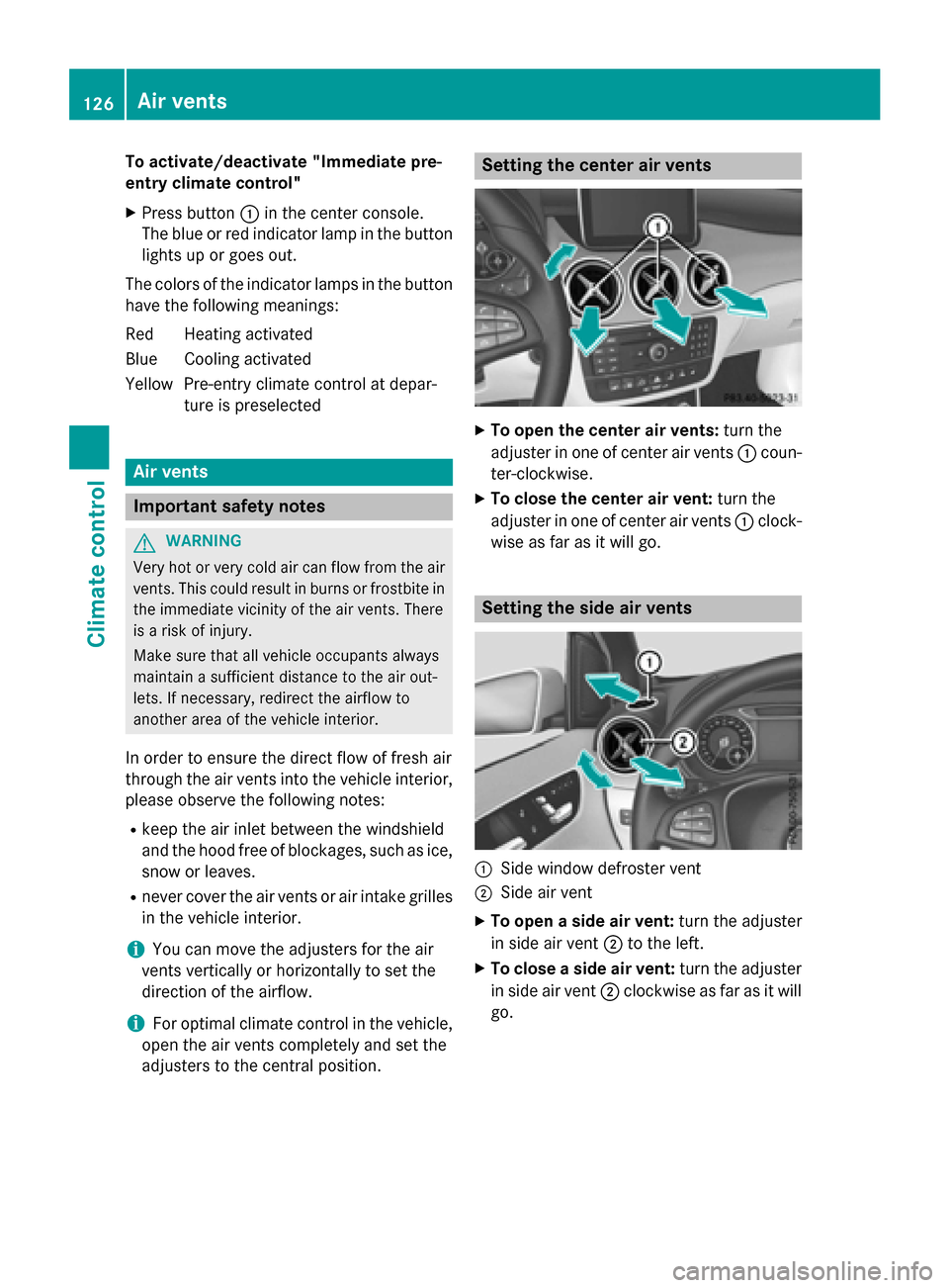
adjusters to the central position. Setting the center air vents
X
To open the center air vents: turn the
adjuster in one of center air vents :coun-
ter-clockwise.
X To close the center air vent: turn the
adjuster in one of center air vents :clock-
wise as far as it will go. Setting the side air vents
:
Side window defroster vent
; Side air vent
X To open a side air vent: turn the adjuster
in side air vent ;to the left.
X To close a side air vent: turn the adjuster
in side air vent ;clockwise as far as it will
go. 126
Air ventsClimate control
Page 134 of 338
The drive system can be switched off while
the vehicle is in motion by pressing and hold- ing the Start/Stop button for three seconds.
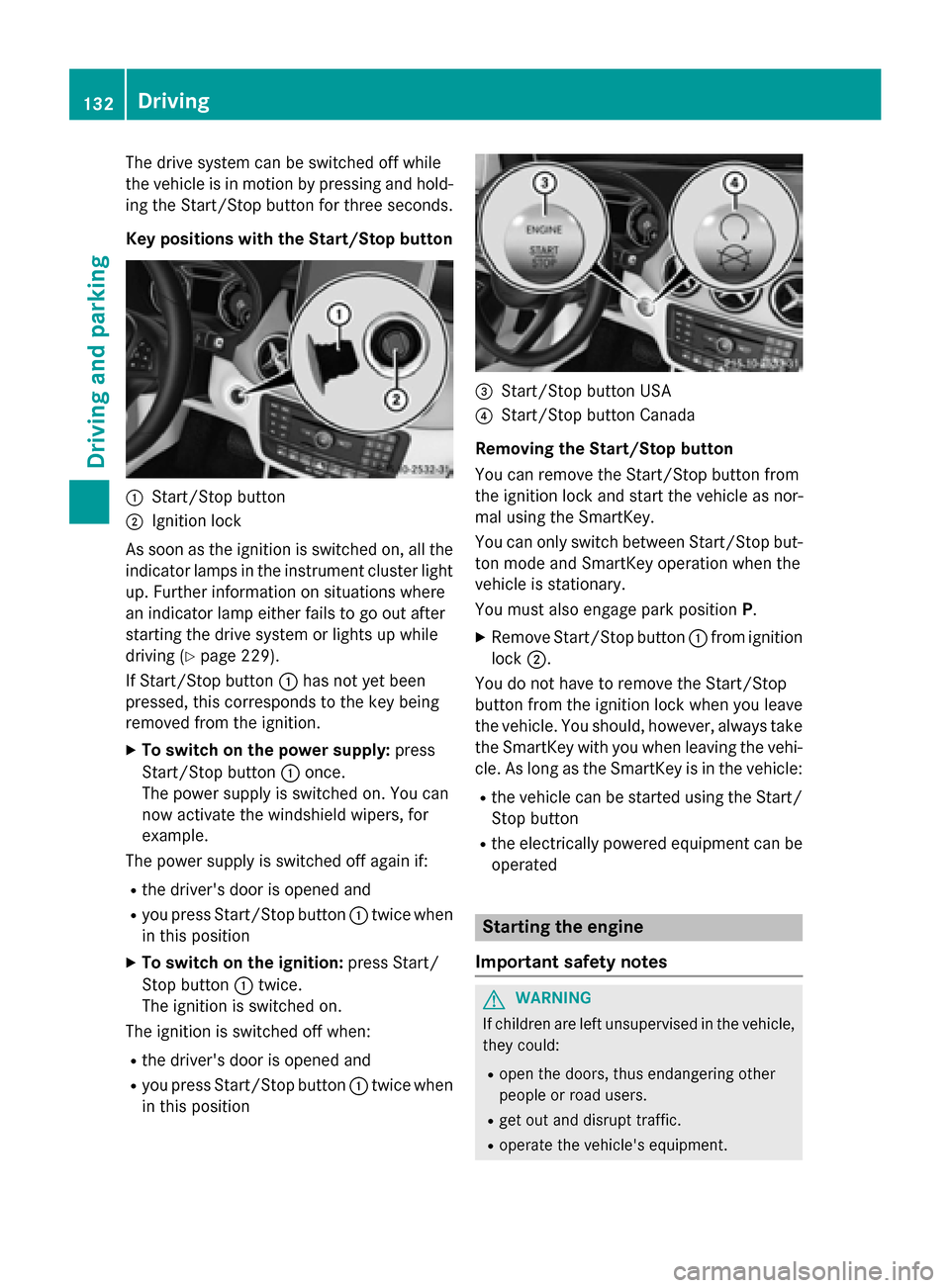
Key positions with the Start/Stop button :
Start/Stop button
; Ignition lock
As soon as the ignition is switched on, all the
indicator lamps in the instrument cluster light up. Further information on situations where
an indicator lamp either fails to go out after
starting the drive system or lights up while
driving (Y page 229).
If Start/Stop button :has not yet been
pressed, this corresponds to the key being
removed from the ignition.
X To switch on the power supply: press
Start/Stop button :once.
The power supply is switched on. You can
now activate the windshield wipers, for
example.
The power supply is switched off again if:
R the driver's door is opened and
R you press Start/Stop button :twice when
in this position
X To switch on the ignition: press Start/
Stop button :twice.
The ignition is switched on.
The ignition is switched off when:
R the driver's door is opened and
R you press Start/Stop button :twice when
in this position =
Start/Stop button USA
? Start/Stop button Canada
Removing the Start/Stop button
You can remove the Start/Stop button from
the ignition lock and start the vehicle as nor-
mal using the SmartKey.
You can only switch between Start/Stop but-
ton mode and SmartKey operation when the
vehicle is stationary.
You must also engage park position P.
X Remove Start/Stop button :from ignition
lock ;.
You do not have to remove the Start/Stop
button from the ignition lock when you leave
the vehicle. You should, however, always take the SmartKey with you when leaving the vehi-cle. As long as the SmartKey is in the vehicle:
R the vehicle can be started using the Start/
Stop button
R the electrically powered equipment can be
operated Starting the engine
Important safety notes G
WARNING
If children are left unsupervised in the vehicle, they could:
R open the doors, thus endangering other
people or road users.
R get out and disrupt traffic.
R operate the vehicle's equipment. 132
DrivingDriving and parking
Page 143 of 338
To avoid hazardous situations, observe the
following:
R Only connect the charging cable to mains
sockets that:
- are installed correctly and
- have been approved by an electrical spe-
cialist.
R For safety reasons, only use the charging
cables supplied with the vehicle, or charg-
ing cables which have been approved for
use with this vehicle.
R Never use a damaged charging cable.
R Do not use:
- Extension cables
- Cable drums
- Multiple sockets
R Do not use a socket adapter to connect the
charging cable to the mains socket. The
only exception is if the adapter has been
tested and approved by the manufacturer
for charging the high-voltage battery in an
electric vehicle.
R Always observe the safety notes in the
socket adapter's operating instructions.
The vehicle's high voltage electrical system is under high voltage.
R Do not handle high-voltage components or
the orange cables of the vehicle's high-volt-age electrical system.
R Do not touch high-voltage components or
the orange cables of the high-voltage elec-
trical system when a vehicle has been
involved in a crash.
R Do not touch any damaged components or
damaged orange cables of the vehicle's
high-voltage electrical system.
R Do not remove the covers of the high-volt-
age electrical system components that are
marked with a warning sticker. General notes
Method of operation The vehicle is equipped with a high-voltage
battery for driving. The high-voltage battery
stores the energy needed to operate the elec-
tric motor and releases it again.
The electric motor uses energy that has been stored in the high-voltage battery when pull-
ing away, accelerating and during the jour-
ney.
In overrun mode (except D+), kinetic energy
is converted by means of energy recuperation
into electrical energy and stored in the high-
voltage battery.
The high-voltage battery can be charged as
follows:
R through energy recuperation while the
vehicle is in motion
R with the charging cable at a mains socket
while the vehicle is stationary
R with the charging cable at a charging sta-
tion while the vehicle is stationary
The high-voltage battery can be charged in a
voltage range from 110 V to 240 V.
If the condition of charge drops to less than
13%, the high-voltage battery reserve indica-
tor lamp lights up in the instrument cluster.
Charge the high-voltage battery as soon as
possible.
Below a condition of charge of 5%, the per-
formance of the vehicle is reduced. The vehi-
cle's high-voltage electrical system switches
off at a condition of charge of 0%.
Use of the pre-entry climate control function
may mean that the high-voltage battery is not fully charged.
Discharged battery The vehicle's high-voltage electrical system
switches off if the high-voltage battery is com-
pletely discharged. 30 seconds prior to this,
you are informed of the switch-off by the
Battery level too low. Stop and Battery level too low. Stop and High-voltage battery
141Driving and parking Z
Page 149 of 338
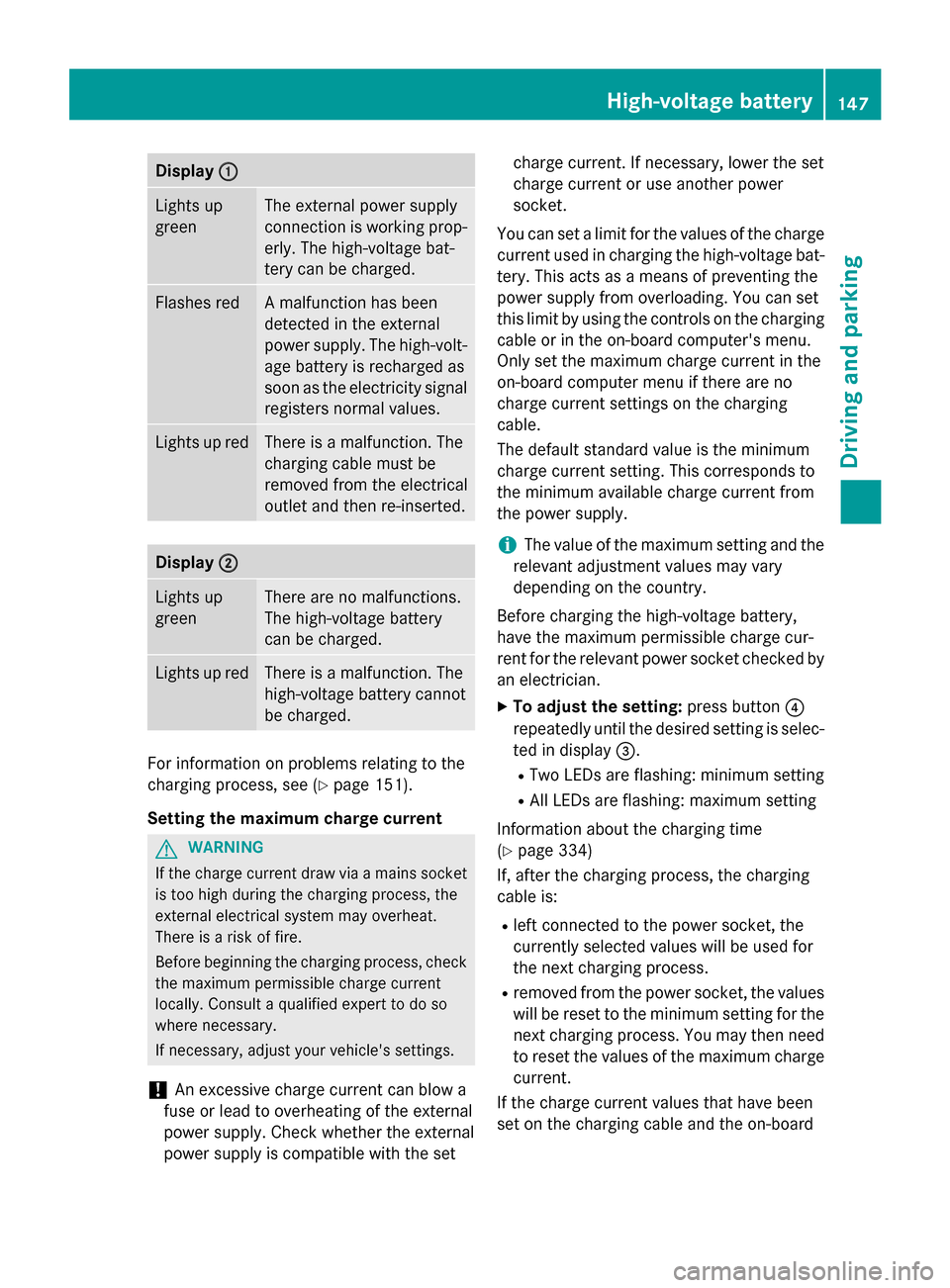
Display
:
: Lights up
green The external power supply
connection is working prop-
erly. The high-voltage bat-
tery can be charged. Flashes red A malfunction has been
detected in the external
power supply. The high-volt-
age battery is recharged as
soon as the electricity signal
registers normal values. Lights up red There is a malfunction. The
charging cable must be
removed from the electrical
outlet and then re-inserted.
Display
; ; Lights up
green There are no malfunctions.
The high-voltage battery
can be charged.
Lights up red There is a malfunction. The
high-voltage battery cannot
be charged. For information on problems relating to the
charging process, see (Y
page 151).
Setting the maximum charge current G
WARNING
If the charge current draw via a mains socket is too high during the charging process, the
external electrical system may overheat.
There is a risk of fire.
Before beginning the charging process, check the maximum permissible charge current
locally. Consult a qualified expert to do so
where necessary.
If necessary, adjust your vehicle's settings.
! An excessive charge current can blow a
fuse or lead to overheating of the external
power supply. Check whether the external
power supply is compatible with the set charge current. If necessary, lower the set
charge current or use another power
socket.
You can set a limit for the values of the charge current used in charging the high-voltage bat-
tery. This acts as a means of preventing the
power supply from overloading. You can set
this limit by using the controls on the charging
cable or in the on-board computer's menu.
Only set the maximum charge current in the
on-board computer menu if there are no
charge current settings on the charging
cable.
The default standard value is the minimum
charge current setting. This corresponds to
the minimum available charge current from
the power supply.
i The value of the maximum setting and the
relevant adjustment values may vary
depending on the country.
Before charging the high-voltage battery,
have the maximum permissible charge cur-
rent for the relevant power socket checked by
an electrician.
X To adjust the setting: press button?
repeatedly until the desired setting is selec- ted in display =.
R Two LEDs are flashing: minimum setting
R All LEDs are flashing: maximum setting
Information about the charging time
(Y page 334)
If, after the charging process, the charging
cable is:
R left connected to the power socket, the
currently selected values will be used for
the next charging process.
R removed from the power socket, the values
will be reset to the minimum setting for the next charging process. You may then need
to reset the values of the maximum charge current.
If the charge current values that have been
set on the charging cable and the on-board High-voltage batte
ry
147Driving an d parking Z
Page 157 of 338
With the Start/Stop button:
X Remove the Start/Stop button from the
ignition lock.
X Insert the SmartKey into the ignition lock.
X Switch on the ignition.
X Depress the brake pedal and keep it
depressed.
X Shift to neutral N.
X Release the brake pedal.
X Release the electric parking brake.
X Switch off the ignition and leave the Smart-
Key in the ignition lock.
If you try to switch off the drive system when the transmission is not in position P:
R a message appears in the multifunction dis-
play
R a warning signal sounds Electric parking brake
General notes G
WARNING
If you leave children unsupervised in the vehi- cle, they could set it in motion by, for example:
R release the parking brake.
R shift the transmission out of park position
P.
R start the vehicle's drive system.
They could also operate the vehicle's equip-
ment. There is a risk of an accident and injury.
When leaving the vehicle, always take the
SmartKey with you and lock the vehicle. Never leave children unsupervised in the vehicle. The function of the electric parking brake and
the parking lock is dependent on the on-board voltage. If the on-board voltage is low or if
there is a malfunction in the system, it may
not be possible to apply the released parking
brake or to shift the transmission to the P
position.
X If this is the case, only park the vehicle on
level ground and secure it to prevent it roll-
ing away.
X Shift the transmission to position P.
It may not be possible to release an applied
parking brake if the on-board voltage is low or
there is a malfunction in the system. Contact a qualified specialist workshop.
The electric parking brake carries out a func-
tion check at regular intervals when the drive
system is switched off. The sounds that can
be heard while this is occurring are normal.
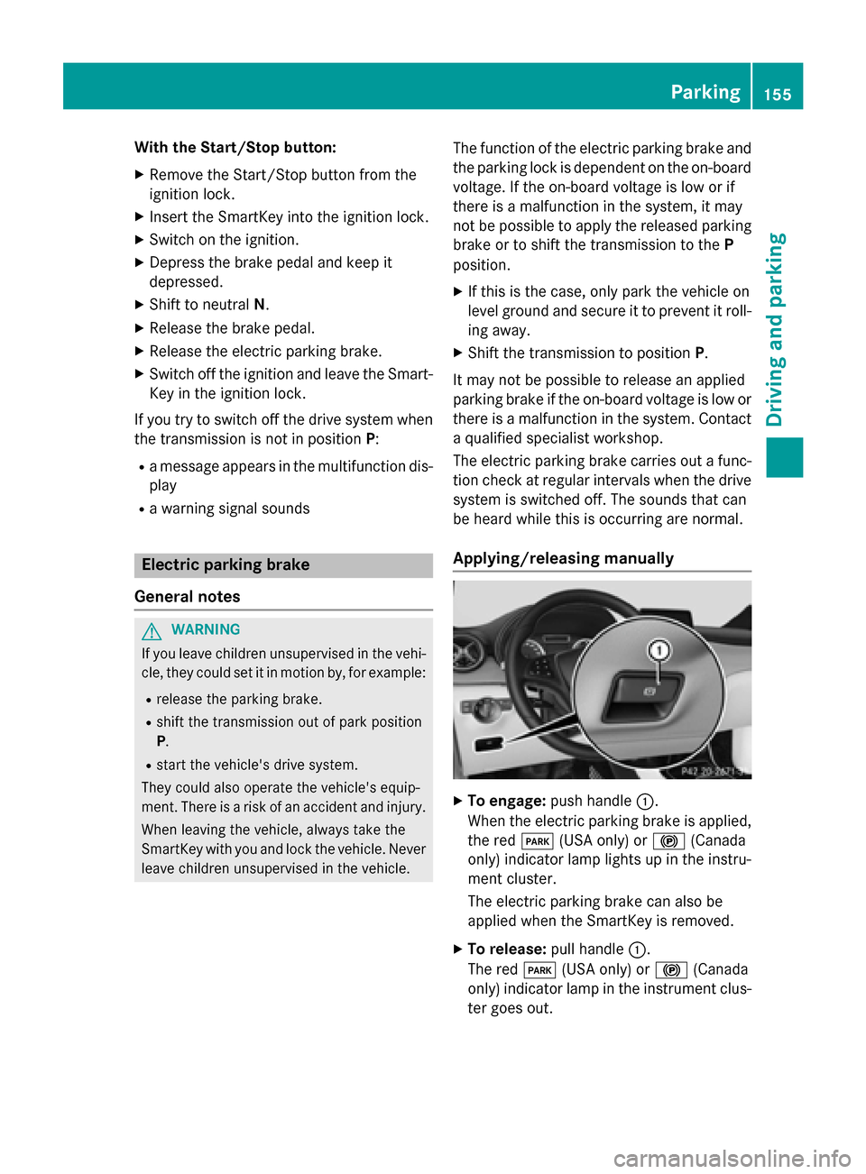
Applying/releasing manually X
To engage: push handle :.
When the electric parking brake is applied, the red F(USA only) or !(Canada
only) indicator lamp lights up in the instru-
ment cluster.
The electric parking brake can also be
applied when the SmartKey is removed.
X To release: pull handle:.
The red F(USA only) or !(Canada
only) indicator lamp in the instrument clus- ter goes out. Parking
155Driving and parking Z