2015 MERCEDES-BENZ B-Class ELECTRIC coolant level
[x] Cancel search: coolant levelPage 9 of 338
COLLISION PREVENTION ASSIST
PLUS
Activating/deactivating ................ .194
Display message ............................ 209
Operation/notes .............................. 64
COMAND
Generated electricity ..................... 142
COMAND display
Cleaning ......................................... 276
Combination switch .......................... 102
Compass
Calibrating ..................................... 265
Calling up ....................................... 264
Magnetic field zone maps .............. 265
Setting .......................................... .265
Consumption statistics (on-board
computer) .......................................... 187
Convenience closing feature .............. 84
Convenience opening feature ............ 84
Convenience opening/closing (air-
recirculation mode) ........................... 123
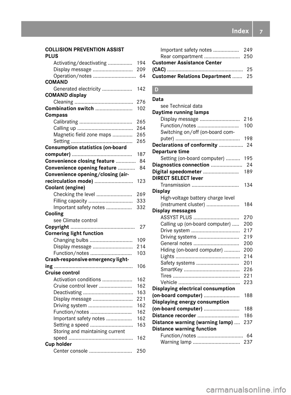
Coolant (engine)
Checking the level ......................... 269
Filling capacity ............................... 333
Important safety notes .................. 332
Cooling
see Climate control
Copyright ............................................. 27
Cornering light function
Changing bulbs .............................. 109
Display message ............................ 214
Function/notes ............................ .103
Crash-responsive emergency light-
ing ....................................................... 106
Cruise control
Activation conditions ..................... 162
Cruise control lever ....................... 162
Deactivating ................................... 163
Display message ............................ 221
Driving system ............................... 162
Function/notes ............................ .162
Important safety notes .................. 162
Setting a speed .............................. 163
Storing and maintaining current
speed ............................................. 162
Cup holder
Center console .............................. 250 Important safety notes .................. 249
Rear compartment ......................... 250
Customer Assistance Center
(CAC) ..................................................... 25
Customer Relations Department ....... 25 D
Data see Technical data
Daytime running lamps
Display message ............................ 216
Function/notes ............................ .100
Switching on/off (on-board com-
puter) ............................................. 198
Declarations of conformity ................. 24
Departure time
Setting (on-board computer) .......... 195
Diagnostics connection ......................24
Digital speedometer .........................189
DIRECT SELECT lever
Transmission ................................. 134
Display
High-voltage battery charge level
(instrument cluster) ....................... 184
Display messages
ASSYST PLUS ................................ 270
Calling up (on-board computer) ..... 200
Drive system .................................. 217
Driving systems ............................ .219
General notes ................................ 200
Hiding (on-board computer) ........... 200
Lights ............................................. 214
Safety systems .............................. 201
SmartKey ....................................... 226
Tires ............................................... 221
Vehicle .......................................... .223
Displaying electrical consumption
(on-board computer) ......................... 188
Displaying energy consumption
(on-board computer) ......................... 188
Distance recorder .............................186
Distance warning (warning lamp) .... 237
Distance warning function
Function/notes ................................ 64
Warning lamp ................................. 237 Index
7
Page 25 of 338
Danger of electric shock
G
DANGER
The vehicle's high voltage electrical system is under high voltage. If you modify components
in the vehicle's high-voltage electrical system or touch damaged components, you may be
electrocuted. The components in the vehi-
cle's high-voltage electrical system may be
damaged in an accident, although the damage
is not visible. There is a risk of fatal injury.
Following an accident, do not touch any high- voltage components and never modify the
vehicle's high-voltage electrical system. Have
the vehicle towed away after an accident and the vehicle's high-voltage electrical system
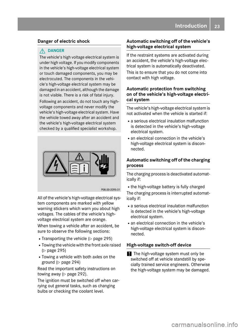
checked by a qualified specialist workshop. All of the vehicle's high-voltage electrical sys-
tem components are marked with yellow
warning stickers which warn you about high
voltages. The cables of the vehicle's high-
voltage electrical system are orange.
When towing a vehicle after an accident, be
sure to observe the following sections:
R Transporting the vehicle (Y page 295)
R Towing the vehicle with the front axle raised
(Y page 295)
R Towing a vehicle with both axles on the
ground (Y page 294)
Read the important safety instructions on
towing away (Y page 292).
The ignition must be switched off when car-
rying out general tasks, such as changing
bulbs or checking the coolant level. Automatic switching off of the vehicle's
high-voltage electrical system If the restraint systems are activated during
an accident, the vehicle's high-voltage elec-
trical system is automatically deactivated.
This is to ensure that you do not come into
contact with high voltage.
Automatic protection from switching
on of the vehicle's high-voltage electri-
cal system The vehicle's high-voltage electrical system is
not activated when the vehicle is started if:
R a serious electrical insulation malfunction
is detected in the vehicle's high-voltage
electrical system.
R an electrical connection in the vehicle's
high-voltage electrical system is discon-
nected.
Automatic switching off of the charging process The charging process is deactivated automat-
ically if:
R the high-voltage battery is fully charged
The charging process is interrupted automat- ically if:
R a serious electrical insulation malfunction
is detected in the vehicle's high-voltage
electrical system.
R an electrical connection in the vehicle's
high-voltage electrical system is discon-
nected.
High-voltage switch-off device !
The high-voltage system must only be
switched off at vehicle standstill by spe-
cially trained service engineers. Otherwise
the high-voltage system may be damaged. Int
roduction
23 Z
Page 219 of 338
Display messages
Possible causes/consequences and
M
MSolutions b
Active Headlamps Active Headlamps
Inoperative Inoperative The light sensor is defective.
X Visit a qualified specialist workshop. b
Switch Off Lights Switch Off Lights The lights are still switched on when you leave the vehicle. A
warning tone also sounds.
X Turn the light switch to Ã.Drive system
Display messages
Possible causes/consequences and
M MSolutions +
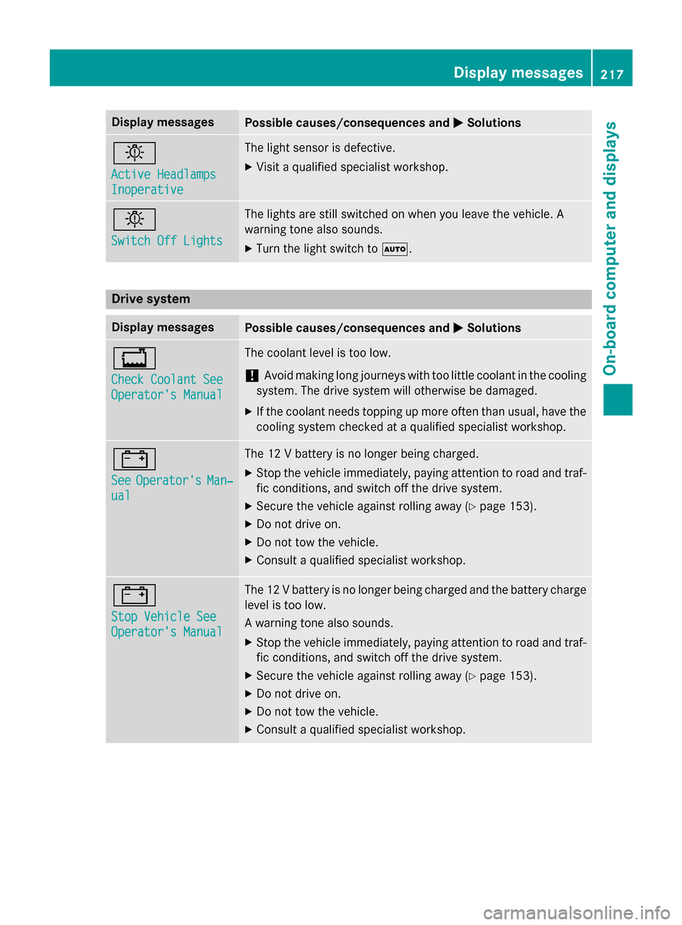
Check Coolant See Check Coolant See
Operator's Manual Operator's Manual The coolant level is too low.
! Avoid making long journeys with too little coolant in the cooling
system. The drive system will otherwise be damaged.
X If the coolant needs topping up more often than usual, have the
cooling system checked at a qualified specialist workshop. #
See See
Operator's
Operator's Man‐
Man‐
ual
ual The 12 V battery is no longer being charged.
X Stop the vehicle immediately, paying attention to road and traf-
fic conditions, and switch off the drive system.
X Secure the vehicle against rolling away (Y page 153).
X Do not drive on.
X Do not tow the vehicle.
X Consult a qualified specialist workshop. #
Stop Vehicle See Stop Vehicle See
Operator's Manual Operator's Manual The 12 V battery is no longer being charged and the battery charge
level is too low.
A warning tone also sounds.
X Stop the vehicle immediately, paying attention to road and traf-
fic conditions, and switch off the drive system.
X Secure the vehicle against rolling away (Y page 153).
X Do not drive on.
X Do not tow the vehicle.
X Consult a qualified specialist workshop. Display
messages
217On-board computer and displays Z
Page 271 of 338
X
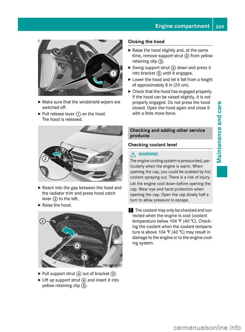
Make sure that the windshield wipers are
switched off.
X Pull release lever :on the hood.
The hood is released. X
Reach into the gap between the hood and
the radiator trim and press hood catch
lever ;to the left.
X Raise the hood. X
Pull support strut ?out of bracket A.
X Lift up support strut ?and insert it into
yellow retaining clip =. Closing the hood X
Raise the hood slightly and, at the same
time, remove support strut ?from yellow
retaining clip =.
X Swing support strut ?down and press it
into bracket Auntil it engages.
X Lower the hood and let it fall from a height
of approximately 8 in (20 cm).
X Check that the hood has engaged properly.
If the hood can be raised slightly, it is not
properly engaged. Do not press the hood
closed. Open the hood again and close it
with a little more force. Checking and adding other service
products
Checking coolant level G
WARNING
The engine cooling system is pressurized, par- ticularly when the engine is warm. When
opening the cap, you could be scalded by hotcoolant spraying out. There is a risk of injury.
Let the engine cool down before opening the
cap. Wear eye and hand protection when
opening the cap. Open the cap slowly half a
turn to allow pressure to escape.
! The coolant may only be checked and cor-
rected when the engine is cool (coolant
temperature below 104 ‡ (40 †). Check-
ing the coolant when the coolant tempera-
ture is above 104 ‡ (40 †) may result in
damage to the engine or to the engine cool- ing system. Engine compartment
269Maintenance and care Z
Page 272 of 338
X
Park the vehicle on a level surface.
Only check the coolant level when the vehi-
cle is on a level surface and the drive sys-
tem has cooled down.
X Turn the SmartKey to position 2in the igni-
tion lock (Y page 131).
X Check the coolant temperature display in
the instrument cluster.
The coolant temperature must be below
104 ‡ (40 †).
X Turn the SmartKey to position 0in the igni-
tion lock (Y page 131).
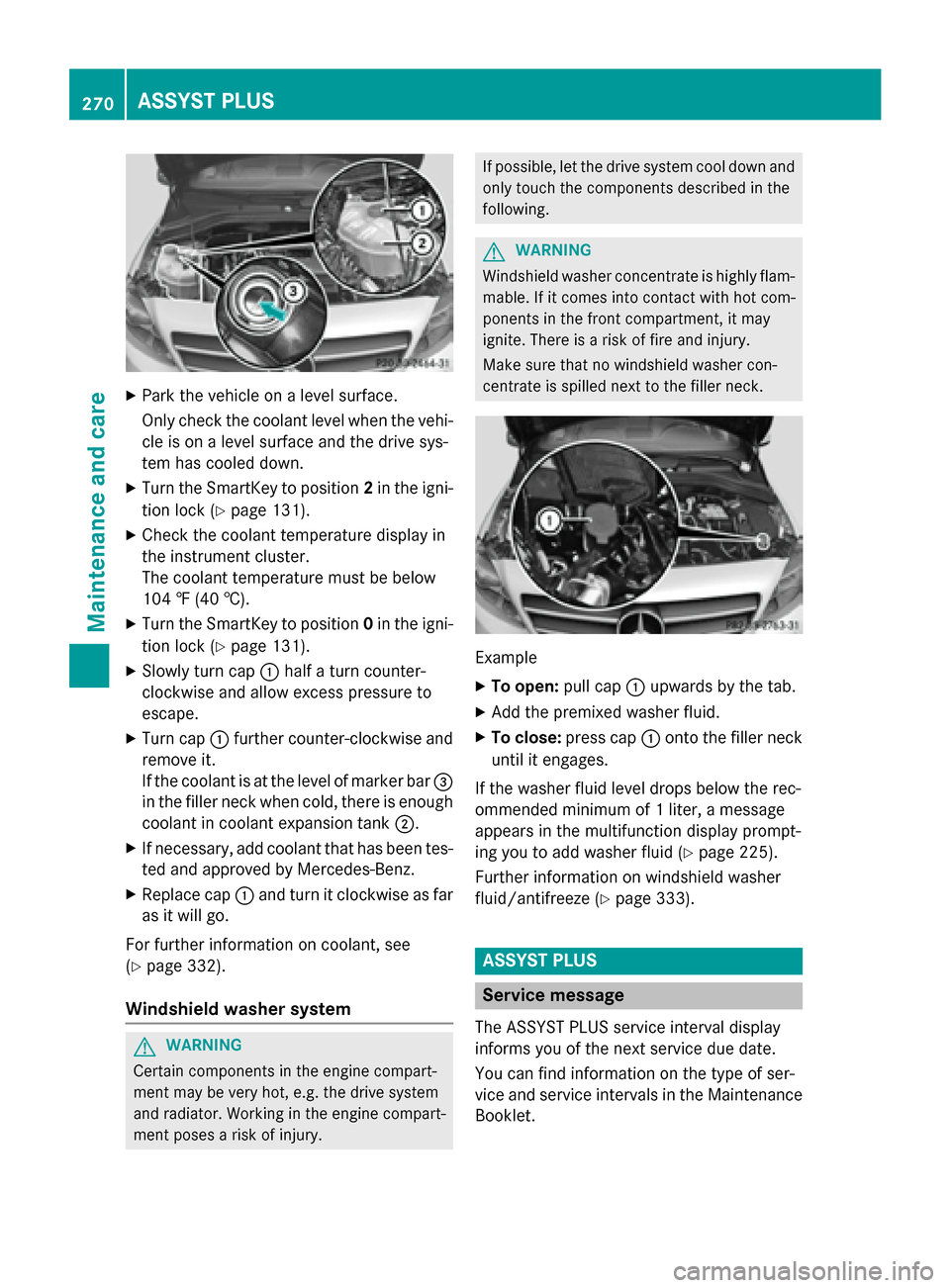
X Slowly turn cap :half a turn counter-
clockwise and allow excess pressure to
escape.
X Turn cap :further counter-clockwise and
remove it.
If the coolant is at the level of marker bar =
in the filler neck when cold, there is enough coolant in coolant expansion tank ;.
X If necessary, add coolant that has been tes-
ted and approved by Mercedes-Benz.
X Replace cap :and turn it clockwise as far
as it will go.
For further information on coolant, see
(Y page 332).
Windshield washer system G
WARNING
Certain components in the engine compart-
ment may be very hot, e.g. the drive system
and radiator. Working in the engine compart-
ment poses a risk of injury. If possible, let the drive system cool down and
only touch the components described in the
following. G
WARNING
Windshield washer concentrate is highly flam- mable. If it comes into contact with hot com-
ponents in the front compartment, it may
ignite. There is a risk of fire and injury.
Make sure that no windshield washer con-
centrate is spilled next to the filler neck. Example
X To open: pull cap:upwards by the tab.
X Add the premixed washer fluid.
X To close: press cap :onto the filler neck
until it engages.
If the washer fluid level drops below the rec-
ommended minimum of 1 liter, a message
appears in the multifunction display prompt-
ing you to add washer fluid (Y page 225).
Further information on windshield washer
fluid/antifreeze (Y page 333). ASSYST PLUS
Service message
The ASSYST PLUS service interval display
informs you of the next service due date.
You can find information on the type of ser-
vice and service intervals in the Maintenance
Booklet. 270
ASSYST PLUSMaintenance and care
Page 322 of 338
Curb weight
The weight of a vehicle with standard equip-
ment including the maximum capacity of fuel, oil and coolant. It also includes the air-condi-
tioning system and optional equipment if
these are installed in the vehicle, but does not include passengers or luggage.
Maximum load rating
The maximum load rating is the maximum
permissible weight in kilograms or lbs for
which a tire is approved.
Maximum permissible tire pressure
Maximum permissible tire pressure for one
tire.
Maximum load on one tire
Maximum load on one tire. This is calculated
by dividing the maximum axle load of one axle by two.
PSI (pounds per square inch)
A standard unit of measure for tire pressure.
Aspect ratio
Relationship between tire height and tire
width in percent.
Tire pressure
This is pressure inside the tire applying an
outward force to each square inch of the tire's
surface. The tire pressure is specified in
pounds per square inch (psi), in kilopascal
(kPa) or in bar. The tire pressure should only
be corrected when the tires are cold.
Cold tire pressure
The tires are cold:
R if the vehicle has been parked without
direct sunlight on the tires for at least three
hours and
R if the vehicle has not been driven further
than 1 mile (1.6 km) Tread
The part of the tire that comes into contact
with the road.
Bead
The tire bead ensures that the tire sits
securely on the wheel. There are several steel
wires in the bead to prevent the tire from
coming loose from the wheel rim.
Sidewall
The part of the tire between the tread and the bead.
Weight of optional extras
The combined weight of those optional extras
that weigh more than the replaced standard
parts and more than 2.3 kg (5 lbs). These
optional extras, such as high-performance
brakes, level control, a roof rack or a high-
performance battery, are not included in the
curb weight and the weight of the accesso-
ries.
TIN (Tire Identification Number)
This is a unique identifier which can be used
by a tire manufacturer to identify tires, for
example for a product recall, and thus identify the purchasers. The TIN is made up of the
manufacturer's identity code, tire size, tire
type code and the manufacturing date.
Load bearing index
The load bearing index (also load index) is a
code that contains the maximum load bearing
capacity of a tire.
Traction
Traction is the result of friction between the
tires and the road surface.
Treadwear indicators
Narrow bars (tread wear bars) that are dis-
tributed over the tire tread. If the tire tread is level with the bars, the wear limit of áin
(1.6 mm) has been reached. 320
All about wheels and tiresWheels and tires
Page 333 of 338
Vehicle identification number (VIN)
X
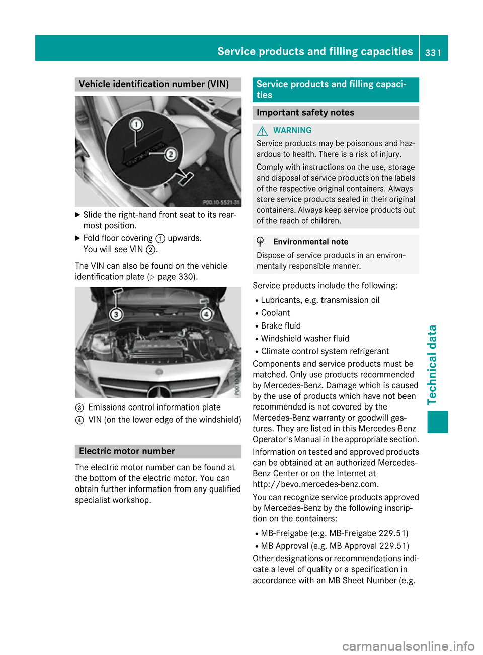
Slide the right-hand front seat to its rear-
most position.
X Fold floor covering :upwards.
You will see VIN ;.
The VIN can also be found on the vehicle
identification plate (Y page 330).=
Emissions control information plate
? VIN (on the lower edge of the windshield) Electric motor number
The electric motor number can be found at
the bottom of the electric motor. You can
obtain further information from any qualified
specialist workshop. Service products and filling capaci-
ties
Important safety notes
G
WARNING
Service products may be poisonous and haz-
ardous to health. There is a risk of injury.
Comply with instructions on the use, storage
and disposal of service products on the labels of the respective original containers. Always
store service products sealed in their original containers. Always keep service products out
of the reach of children. H
Environmental note
Dispose of service products in an environ-
mentally responsible manner.
Service products include the following:
R Lubricants, e.g. transmission oil
R Coolant
R Brake fluid
R Windshield washer fluid
R Climate control system refrigerant
Components and service products must be
matched. Only use products recommended
by Mercedes-Benz. Damage which is caused
by the use of products which have not been
recommended is not covered by the
Mercedes-Benz warranty or goodwill ges-
tures. They are listed in this Mercedes-Benz
Operator's Manual in the appropriate section.
Information on tested and approved products can be obtained at an authorized Mercedes-
Benz Center or on the Internet at
http://bevo.mercedes-benz.com.
You can recognize service products approved
by Mercedes-Benz by the following inscrip-
tion on the containers:
R MB-Freigabe (e.g. MB-Freigabe 229.51)
R MB Approval (e.g. MB Approval 229.51)
Other designations or recommendations indi- cate a level of quality or a specification in
accordance with an MB Sheet Number (e.g. Service products and filling capacities
331Technical data Z
Page 335 of 338
The antifreeze/corrosion inhibitor concentra-
tion in the engine cooling system should:
R be at least 50%. This will protect the engine
cooling system against freezing down to
approximately -35 ‡ (-37 †).
R not exceed 55% (antifreeze protection
down to -49 ‡ [-45 †]). Otherwise, heat
will not be dissipated as effectively.
Mercedes-Benz recommends coolant or anti- freeze/corrosion inhibitor concentrate in
accordance with
MB Specifications for Service Products 310.1
.
i When the vehicle is first delivered, it is fil-
led with a coolant mixture that ensures
adequate antifreeze and corrosion protec-
tion.
i The coolant is checked with every main-
tenance interval at a qualified specialist
workshop.
Filling capacities Missing values were not available at time of
going to print.
Model Capacity
All models
Windshield washer system
Important safety notes G
WARNING
Windshield washer concentrate could ignite if it comes into contact with hot engine compo-
nents or the exhaust system. There is a risk of
fire and injury.
Make sure that no windshield washer con-
centrate is spilled next to the filler neck.
! Do not add distilled or de-ionized water to
the washer fluid container. Otherwise, the
level sensor may be damaged. !
Only MB SummerFit and MB WinterFit
washer fluid should be mixed together. The
spray nozzles may otherwise become
blocked.
When handling washer fluid, observe the
important safety notes on service products
(Y page 331).
At temperatures above freezing:
X Fill the washer fluid reservoir with a mixture
of water and windshield washer fluid, e.g.
MB SummerFit.
Add 1 part MB SummerFit to 100 parts water.
At temperatures below freezing:
X Fill the washer fluid reservoir with a mixture
of water and washer fluid, e.g. MB Winter-
Fit.
For the correct mixing ratio refer to the
information on the antifreeze reservoir.
i Add windshield washer fluid, e.g. MB
SummerFit or MB WinterFit, to the washer
fluid all year round. Climate control system refrigerant
Important safety notes The climate control system of your vehicle is
filled with refrigerant R‑
134a.
The instruction label regarding the refrigerant type used can be found on the left, on the
underside of the hood.
! Only the refrigerant R‑134a and the PAG
oil approved by Mercedes-Benz may be
used. The approved PAG oil may not be
mixed with any other PAG oil that is not
approved for R-134a refrigerant. Other-
wise, the climate control system may be
damaged.
Service work, such as topping up refrigerant
or replacing components, may only be carried
out by a qualified specialist workshop. All
applicable regulations must be adhered to,
SAE standard J639 included. Service products and filling capacities
333Technical data Z