2015 MERCEDES-BENZ B-Class ELECTRIC change time
[x] Cancel search: change timePage 242 of 338
Useful information
i This Operator's Manual describes all
models and all standard and optional equip- ment of your vehicle available at the time of
publication of the Operator's Manual.
Country-specific differences are possible.
Please note that your vehicle may not be
equipped with all features described. This
also applies to safety-related systems and
functions.
i Read the information on qualified special-
ist workshops (Y page 25). Loading guidelines
G
WARNING
If objects, luggage or loads are not secured or not secured sufficiently, they could slip, tip
over or be flung around and thereby hit vehicle
occupants. There is a risk of injury, particu-
larly in the event of sudden braking or a sud-
den change in direction.
Always store objects so that they cannot be
flung around. Secure objects, luggage or
loads against slipping or tipping before the
journey.
The handling characteristics of a laden vehi-
cle are dependent on the distribution of the
load within the vehicle. For this reason, you
should observe the following notes when
transporting a load:
R Never exceed the maximum permissible
gross vehicle mass or the gross axle weight rating for the vehicle (including occupants).
The values are specified on the vehicle
identification plate on the B-pillar of the
driver's door.
R The cargo compartment is the preferred
place to carry objects.
R Position heavy loads as far forwards as pos-
sible and as low down in the cargo com-
partment as possible. R
The load must not protrude above the
upper edge of the seat backrests.
R Always place the load against the rear or
front seat backrests. Make sure that the
seat backrests are securely locked into
place.
R Always place the load behind unoccupied
seats if possible.
R Use the cargo tie-down rings and the parcel
nets to transport loads and luggage.
R Use cargo tie-down rings and fastening
materials appropriate for the weight and
size of the load.
R Hook in the cargo net when loading.
R The maximum load capacity of the stowage
well under the cargo compartment floor is
55 lbs (25 kg).
R Secure the load with sufficiently strong and
wear-resistant tie-downs. Pad sharp edges
for protection.
! Do not position the load on one part of the
folding cargo compartment floor only. The
maximum load capacity of the folding cargo
compartment floor is 220 lbs (100 kg). Dis-
tribute the weight evenly to avoid damaging
the cargo compartment floor. Place a solid board under the load if necessary. Please
note that the load on the cargo compart-
ment floor will be increased when the load
is lashed down. Stowage areas
Stowage spaces
Important safety notes G
WARNING
If objects in the passenger compartment are
stowed incorrectly, they can slide or be
thrown around and hit vehicle occupants.
There is a risk of injury, particularly in the
event of sudden braking or a sudden change
in direction. 240
Stowage areasStowage and features
Page 244 of 338
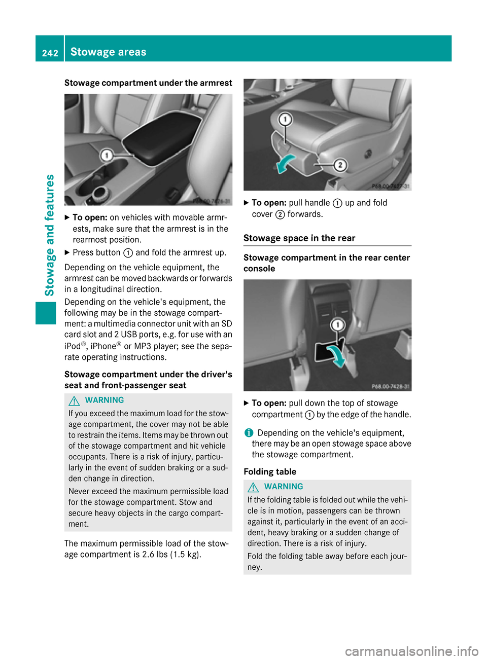
Stowage compartment under the armrest
X
To open: on vehicles with movable armr-
ests, make sure that the armrest is in the
rearmost position.
X Press button :and fold the armrest up.
Depending on the vehicle equipment, the
armrest can be moved backwards or forwards
in a longitudinal direction.
Depending on the vehicle's equipment, the
following may be in the stowage compart-
ment: a multimedia connector unit with an SD
card slot and 2 USB ports, e.g. for use with an
iPod ®
, iPhone ®
or MP3 player; see the sepa-
rate operating instructions.
Stowage compartment under the driver's seat and front-passenger seat G
WARNING
If you exceed the maximum load for the stow- age compartment, the cover may not be ableto restrain the items. Items may be thrown out
of the stowage compartment and hit vehicle
occupants. There is a risk of injury, particu-
larly in the event of sudden braking or a sud-
den change in direction.
Never exceed the maximum permissible load
for the stowage compartment. Stow and
secure heavy objects in the cargo compart-
ment.
The maximum permissible load of the stow-
age compartment is 2.6 lbs (1.5 kg). X
To open: pull handle :up and fold
cover ;forwards.
Stowage space in the rear Stowage compartment in the rear center
console
X
To open: pull down the top of stowage
compartment :by the edge of the handle.
i Depending on the vehicle's equipment,
there may be an open stowage space above the stowage compartment.
Folding table G
WARNING
If the folding table is folded out while the vehi- cle is in motion, passengers can be thrown
against it, particularly in the event of an acci- dent, heavy braking or a sudden change of
direction. There is a risk of injury.
Fold the folding table away before each jour-
ney. 242
Stowage areasStowage and features
Page 279 of 338
X
Wipe the plastic trim with a damp, lint-free
cloth, e.g. a microfiber cloth.
X Heavy soiling: use care and cleaning prod-
ucts recommended and approved by
Mercedes-Benz.
The surface may change color temporarily.
Wait until the surface is dry again.
Cleaning the steering wheel and gear or selector lever X
Thoroughly wipe with a damp cloth or use
leather care agents that have been recom-
mended and approved by Mercedes-Benz.
Cleaning genuine wood and trim ele-
ments !
Do not use solvent-based cleaning agents
such as tar remover, wheel cleaners, pol-
ishes or waxes. There is otherwise a risk of damaging the surface.
! Do not use chrome polish on trim pieces.
The trim pieces have a chrome look but are mostly made of anodized aluminum and
can lose their shine if chrome polish is
used. Use a damp, lint-free cloth instead
when cleaning the trim pieces.
If the chrome-plated trim pieces are very
dirty, you can use a chrome polish. If you
are unsure as to whether the trim pieces
are chrome-plated or not, consult an
authorized Mercedes-Benz Center.
X Wipe the wooden trim and trim pieces with
a damp, lint-free cloth, e.g. a microfiber
cloth.
X Heavy soiling: use care and cleaning prod-
ucts recommended and approved by
Mercedes-Benz.
Cleaning the seat covers General notes
! Do not use microfiber cloths to clean gen-
uine leather, artificial leather or DINAMICA covers. If used often, these can damage the
cover.
Note that regular care is essential to ensure
that the appearance and comfort of the cov-
ers is retained over time.
Genuine leather seat covers
! To retain the natural appearance of the
leather, observe the following cleaning
instructions:
R Clean genuine leather covers carefully
with a damp cloth and then wipe the cov-
ers down with a dry cloth.
R Make sure that the leather does not
become soaked. It may otherwise
become rough and cracked.
R Only use leather care agents that have
been tested and approved by Mercedes-
Benz. You can obtain these from a quali- fied specialist workshop.
Leather is a natural product.
It exhibits natural surface characteristics, for
example:
R differences in the texture
R marks caused by growth and injury
R slight nuances of color
These are characteristics of leather and not
material defects.
Seat covers of other materials
! Observe the following when cleaning:
R clean artificial leather covers with a cloth
moistened with a solution containing 1% detergent (e.g. dish washing liquid).
R clean cloth covers with a microfiber cloth
moistened with a solution containing 1%
detergent (e.g. dish washing liquid). Rub
carefully and always wipe entire seat sec- tions to avoid leaving visible lines. Leave
the seat to dry afterwards. Cleaning
results depend on the type of dirt and
how long it has been there.
R clean DINAMICA covers with a damp
cloth. Make sure that you wipe entire Care
277Maintenance and care Z
Page 282 of 338
Useful information
i This Operator's Manual describes all
models and all standard and optional equip- ment of your vehicle available at the time of
publication of the Operator's Manual.
Country-specific differences are possible.
Please note that your vehicle may not be
equipped with all features described. This
also applies to safety-related systems and
functions.
i Read the information on qualified special-
ist workshops (Y page 25). Where will I find...?
Vehicle tool kit
General notes Vehicles with a TIREFIT kit: the TIREFIT kit is
located in the stowage well under the cargo
compartment floor.
Vehicles with a tire-change tool kit: the tire-
change tool kit is in the stowage well under
the cargo compartment floor.
i Apart from certain country-specific varia-
tions, the vehicles are not equipped with a
tire-change tool kit. Some tools for chang-
ing a wheel are specific to the vehicle. For
more information on which tire changing
tools are required and approved to perform
a wheel change on your vehicle, consult a
qualified specialist workshop.
Tools required for changing a wheel may
include, for example:
R Jack
R Wheel chock
R Lug wrench
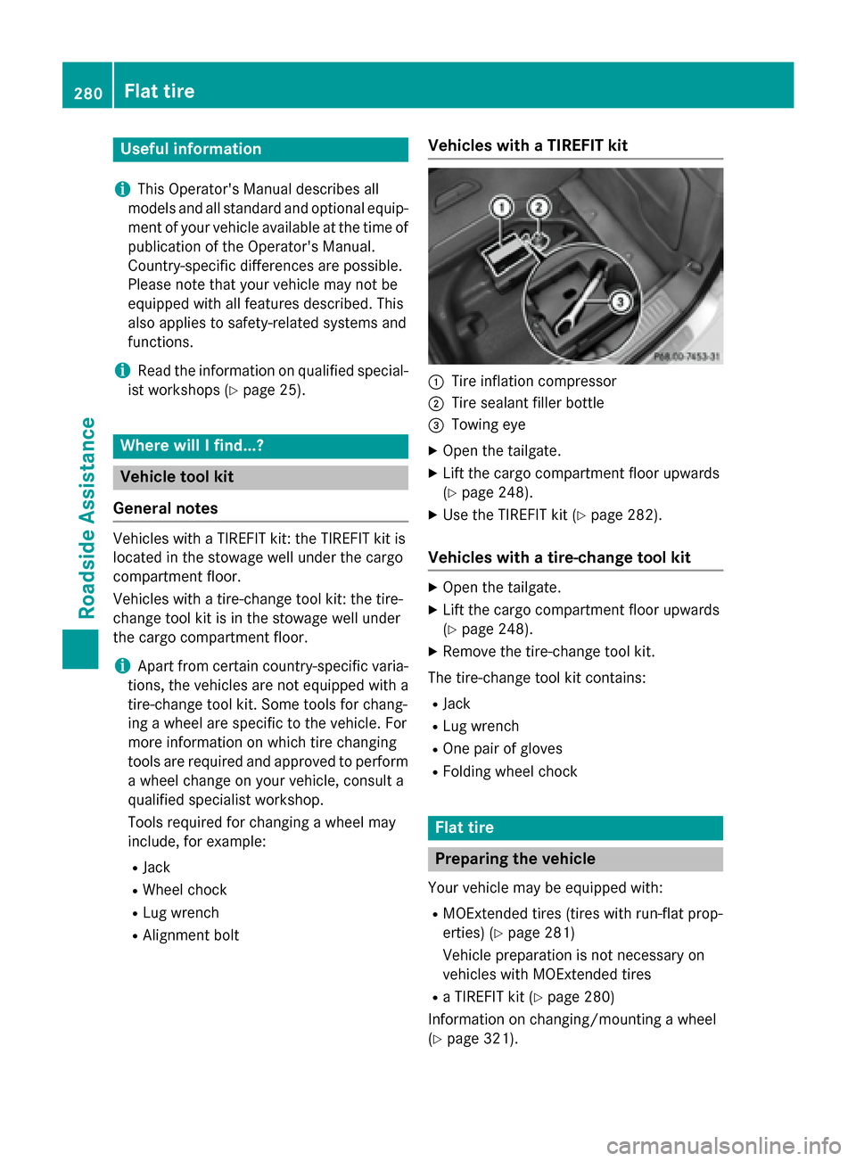
R Alignment bolt Vehicles with a TIREFIT kit
:
Tire inflation compressor
; Tire sealant filler bottle
= Towing eye
X Open the tailgate.
X Lift the cargo compartment floor upwards
(Y page 248).
X Use the TIREFIT kit (Y page 282).
Vehicles with a tire-change tool kit X
Open the tailgate.
X Lift the cargo compartment floor upwards
(Y page 248).
X Remove the tire-change tool kit.
The tire-change tool kit contains: R Jack
R Lug wrench
R One pair of gloves
R Folding wheel chock Flat tire
Preparing the vehicle
Your vehicle may be equipped with:
R MOExtended tires (tires with run-flat prop-
erties) (Y page 281)
Vehicle preparation is not necessary on
vehicles with MOExtended tires
R a TIREFIT kit (Y page 280)
Information on changing/mounting a wheel
(Y page 321). 280
Flat tireRoadside Assistance
Page 311 of 338
Checking the tire pressure electroni-
cally
X
Make sure that the SmartKey is in position
2 in the ignition lock (Y page 131).
X Press =or; on the steering wheel
to select the Serv. Serv.menu.
X Press the 9or: button to select
Tire Pressure
Tire Pressure.
X Press the abutton.
The current tire pressure of each tire is
shown in the multifunction display.
If the vehicle was parked for longer than
20 minutes, the Tire pressure will be
Tire pressure will be
displayed after driving a few
displayed after driving a few
minutes minutes message is shown.
After a teach-in process, the tire pressure
monitor automatically detects new wheels or
new sensors. As long as a clear allocation of
the tire pressure value to the individual
wheels is not possible, the Tire Pressure
Tire Pressure
Monitor Active Monitor Active message is shown instead
of the tire pressure display. The tire pressures are already being monitored.
Tire pressure monitor warning mes-
sages If the tire pressure monitor detects a pressure
loss in one or more tires, a warning message
is shown in the multifunction display and the yellow tire pressure monitor warning lamp
comes on.
R If the Please Correct Tire Pressure
Please Correct Tire Pressure
message appears in the multifunction dis-
play, the tire pressure in at least one tire is
too low and must be corrected at the next
opportunity.
R If the Check Tire Pressure Check Tire Pressure message
appears in the multifunction display, the
tire pressure in one or more tires has drop-
ped significantly and the tires must be
checked.
R If the Tire Pressure Warning Tire Tire Pressure Warning Tire
Failure
Failure message appears in the multi-
function display, the tire pressure in one or more tires has dropped suddenly and the
tires must be checked.
Observe the instructions and safety notes in
the display messages in the "Tires" section
(Y page 221).
If the wheel positions on the vehicle are rota-
ted, the tire pressures may be displayed for
the wrong positions for a short time. This is
rectified after a few minutes of driving, and
the tire pressures are displayed for the cor-
rect positions.
Restarting the tire pressure monitor When you restart the tire pressure monitor, all
existing warning messages are deleted and
the warning lamps go out. The monitor uses
the currently set tire pressures as the refer-
ence values for monitoring. In most cases, the tire pressure monitor will automatically
detect the new reference values after you
have changed the tire pressure. However, you
can also define reference values manually as
described here. The tire pressure monitor
then monitors the new tire pressure values.
X Set the tire pressure to the value recom-
mended for the corresponding driving sit-
uation on the Tire and Loading Information
placard on the driver's side
B-pillar (Y page 303).
Additional tire pressure values for different operating conditions can also be found on
the tire pressure table on the inside of the
charge socket flap (Y page 148).
X Make sure that the tire pressure is correct
on all four wheels.
X Make sure that the SmartKey is in position
2 in the ignition lock (Y page 131).
X Press =or; on the steering wheel
to select the Serv.
Serv. menu.
X Press the 9or: button to select
Tire Pressure
Tire Pressure.
X Press the abutton.
The multifunction display shows the cur-
rent tire pressure for each tire or the Tire Tire Tire pressure
309Wheels and tires Z
Page 323 of 338

Occupant distribution
The distribution of occupants in a vehicle at
their designated seating positions.
Total load limit
Nominal load and luggage load plus 68 kg
(150 lbs) multiplied by the number of seats in the vehicle. Changing a wheel
Flat tire
The "Breakdown assistance" section
(Y page 280) contains information and notes
on how to deal with a flat tire. Information on driving with MOExtended tires in the event of
a flat tire can be found under "MOExtended
tires (tires with run-flat characteristics"
(Y page 281). Rotating the wheels
G
WARNING
Interchanging the front and rear wheels may
severely impair the driving characteristics if
the wheels or tires have different dimensions. The wheel brakes or suspension components
may also be damaged. There is a risk of acci-
dent.
Rotate front and rear wheels only if the wheels and tires are of the same dimensions.
! On vehicles equipped with a tire pressure
monitor, electronic components are loca-
ted in the wheel.
Tire-mounting tools should not be used
near the valve. This could damage the elec- tronic components.
Only have tires changed at a qualified spe-cialist workshop.
Observe the instructions and safety notes in
the "Changing a wheel" section (Y page 321).
The wear patterns on the front and rear tires
differ, depending on the operating conditions. Rotate the wheels before a clear wear pattern has formed on the tires. Front tires typically
wear more on the shoulders and the rear tires
in the center.
If your vehicle's tire configuration allows, you can rotate the wheels according to the inter-
vals in the tire manufacturer's warranty book
in your vehicle documents. If no warranty
book is available, the tires should be rotated
every 3,000 to 6,000 miles (5,000 to
10,000 km), or earlier if tire wear requires.
Ensure the direction of rotation is maintained.
Clean the contact surfaces of the wheel and
the brake disc thoroughly every time a wheel
is rotated. Check the tire pressure and reac-
tivate the tire pressure monitor if necessary. Direction of rotation
Tires with a specified direction of rotation
have additional benefits, e.g. if there is a risk
of hydroplaning. These advantages can only
be gained if the tires are installed correspond- ing to the direction of rotation.
An arrow on the sidewall of the tire indicates
its correct direction of rotation. Storing wheels
Store wheels that are not being used in a cool, dry and preferably dark place. Protect the
tires against oil and grease. Mounting a wheel
Preparing the vehicle X
Stop the vehicle on solid, non-slippery and
level ground.
X Apply the electric parking brake manually.
X Bring the front wheels into the straight-
ahead position.
X Shift the transmission to position P.
X Switch off the engine.
X Vehicles without KEYLESS-GO: remove
the SmartKey from the ignition lock. Changing a wheel
321Wheels and tires Z
Page 325 of 338
tion the jack correctly, the vehicle may be
damaged.
The jacking points are recesses in the lower
door sill. They can only be seen from under- neath. There is one located behind each of
the front wheel arches and in front of the
rear wheel arches.
Position the jack in the jacking points so
that when viewed from the side, the jack is
in the vertical position.
! Position a suitable jack only on the jack-
ing points intended for this purpose.
Never position the jack on the high-voltage
battery. Do not jack up the vehicle on the
high-voltage battery. There is otherwise a
risk of damaging the high-voltage battery.
Also observe the notes in the "Changing a
wheel" section.
Observe the following when raising the
vehicle:
R To raise the vehicle, only use the vehicle-
specific jack that has been tested and
approved by Mercedes-Benz. If used incor-
rectly, the jack could tip over with the vehi-
cle raised.
R The jack is designed only to raise and hold
the vehicle for a short time while a wheel
is being changed. It is not suited for per-
forming maintenance work under the vehi- cle.
R Avoid changing the wheel on uphill and
downhill slopes.
R Before raising the vehicle, secure it from
rolling away by applying the parking brake
and inserting wheel chocks. Do not disen-
gage the parking brake while the vehicle is
raised.
R The jack must be placed on a firm, flat and
non-slip surface. On a loose surface, a
large, flat, load-bearing underlay must be
used. On a slippery surface, a non-slip
underlay must be used, e.g. rubber mats.
R Do not use wooden blocks or similar
objects as a jack underlay. Otherwise, the
jack will not be able to achieve its load- bearing capacity due to the restricted
height.
R Make sure that the distance between the
underside of the tires and the ground does
not exceed 1.2 in (3 cm).
R Never place your hands and feet under the
raised vehicle.
R Do not lie under the vehicle.
R Do not start the drive system when the
vehicle is raised.
R Never open or close a door or the tailgate
when the vehicle is raised.
R Make sure that no persons are present in
the vehicle when the vehicle is raised. X
Using lug wrench :, loosen the bolts on
the wheel you wish to change by about one full turn. Do not unscrew the bolts com-
pletely. Jacking points
The jacking points are located just behind the front wheel housings and just in front of the
rear wheel housings (arrows). Changing a
wheel
323Wheels an d tires Z