Page 9 of 36
 with Tire Inflation Indicator
A Tire Pressure Low - Add Air
warning message will
appear in the vehicle information display
1 and")
7
essential information
Tire Pressure Monitoring System (TPMS) with Tire Inflation Indicator
A Tire Pressure Low - Add Air
warning message will
appear in the vehicle information display
1 and the
low tire pressure warning light 2 will illuminate when
one or more tires are low in pressure and air is needed.
•
The tire pressures should be checked when the
tires are cold. The tires are considered cold after
the vehicle has been parked for 3 hours or more or
driven less than 1 mi (1.6 km) at moderate speeds.
When adding air to an under-inflated tire, the TPMS
with Tire Inflation Indicator provides visual and audible signals to hel\
p you
inflate the tire to the recommended COLD tire pressure.
To use the tire inflation indicator:
1.
Move the shift lever to the
P (PARK) position and apply the parking brake.
2.
Place the ignition switch in the
ON position. Do not start the engine.
3.
Add air to the under-inflated tire, and within a few seconds, the hazard\
warning lights will
start flashing.
4.
When the designated tire pressure is reached, the horn will beep once an\
d the hazard
warning flashers will stop flashing.
5.
Repeat this procedure for any additional under-inflated tires.
After tire pressures are adjusted, drive the vehicle at speeds above 16 \
mph (25 km/h). The
Tire Pressure Low - Add Air warning message and low tire pressure warning light
will extinguish.
Hybrid Awareness
Your vehicle is virtually silent in the electric mode. If you exit your \
vehicle while it is ON
but the engine is not running, the engine will automatically start, info\
rming you that the
car is still ON.
Do not store your INFINITI Intelligent Key within the detection range of\
the vehicle. This
may cause welcome lights and other functions to activate, creating unwan\
ted battery drain.
The hybrid system is designed for optimum efficiency and performance. Ac\
tivation of the
electric mode may vary with driving conditions and driver input. A full \
battery display does
not indicate the vehicle should be in the electric mode.
For more information, refer to the “HEV Overview (section HEV)” of your Owner’s Manual.
Direct Response Hybrid Warning Light
This light will illuminate when the ignition switch is in the ON position
and will extinguish when the hybrid system is started.
The light will also illuminate when a malfunction occurs in the
electric motor or hybrid system.
When this light illuminates while driving, immediately stop the vehicle \
in a safe location
and contact an INFINITI retailer.
If the hybrid system warning light blinks while driving, it may indicate\
that the Li-ion
battery charge is low and you cannot continue to drive.
For more information, refer to the “Instruments and controls (section 2)” of your Owner’s Manual.
1
2
Page 10 of 36

8
essential information
Loose Fuel Cap
A LOOSE FUEL CAP warning message will appear
in the vehicle information display
1 when the
fuel-filler cap is not tightened correctly.
To tighten, turn the cap clockwise until a single
click is heard.
The warning message will extinguish when the vehicle
detects the fuel-filler cap is properly tightened and the
reset button
2 is pressed for about 1 second. If the cap is not properly tightened, the Malfunction Indicator Light
may illuminate.
For more information, refer to the “Instruments and controls (section 2)” and the “Pre-driving checks and adjustments
(section 3)” of your Owner’s Manual.
1
2
When the low tire pressure warning light flashes for approximately 1 min\
ute and then remains
on, the TPMS is not functioning properly. Have the system checked by an \
INFINITI retailer.
Tire pressure rises and falls depending on the heat caused by the vehicl\
e’s operation and the
outside temperature. Low outside temperature can lower the temperature o\
f the air inside
the tire, which can cause a lower tire inflation pressure. This may caus\
e the low tire pressure
warning light to illuminate. If the warning light illuminates, check the\
tire pressure in your tires.
•
Check the tire pressure (including the spare tire) often and always pr\
ior to long distance trips.
The Tire and Loading Information label contains valuable information. Pl\
ease refer to
“Technical and consumer information (section 9)” in your Owner’\
s Manual for the location
of the Tire and Loading Information label.
For more information, refer to the “Instruments and controls (section 2)”, the “Starting and driving (section 5)” and the
“Maintenance and do-it-yourself (section 8)” of your Owner’s Manual.
Fuel-filler Door
The fuel-filler door is located on the driver’s side of the vehicle.
The fuel-filler door automatically locks or unlocks
when the driver’s door is locked or unlocked.
To open the fuel-filler door, push the right side of
the fuel-filler door and release.
For more information, refer to the “Pre-driving checks and adjustments (section 3)” of your Owner’s Manual.
Towing Your Vehicle
All-Wheel Drive (AWD) Vehicle:
•
An all-wheel drive vehicle must be towed with all wheels off the ground,\
even if the
vehicle is placed in the 2WD mode.
For proper towing and to avoid accidental damage to your vehicle, NISSAN\
recommends
that a service operator tow your vehicle after carefully reading the Own\
er’s manual
precautions.
For more information, refer to the “In case of emergency (section 6)” of your Owner’s Manual.
Page 11 of 36
” of
your Owner’s Manua")
9
Accessing the Front Cup Holders
To open the cup holders, push the lid 1 down
and release.
For more information, refer to the “Instruments and controls (section 2)” of
your Owner’s Manual.
1
Front Armrest/Center Console Storage Box
To access the top storage bin, pull up on the driver’s
side lever 1. To access the bottom storage bin, pull up on the
passenger’s side lever 2.
For more information, refer to the “Instruments and controls (section 2)” of your Owner’s Manual.
12
Clock Set/Adjustment
DIGITAL CLOCK ADJUSTMENT
To adjust the time and the appearance of the clock
on the display:
1.
Press the
SETTING button on the control panel.
2.
Touch the
Others key.
3.
Touch the
Clock key.
The following settings can be adjusted:
•
On-screen Clock:
The clock in the upper right corner of the display can be turned ON
or OFF.
•
Clock Format (24h):
The clock can be set to 12 hours or 24 hours.
•
Offset (hour):
The time can be adjusted by increasing or decreasing per hour.
•
Offset (min):
The time can be adjusted by increasing or decreasing per minute.
•
Daylight Savings Time:
The application of daylight savings time can be turned ON or OFF.
•
Time Zone:
Adjust the time zone. Choose a time zone from the available list.
Press the BACK button to return to the previous screen.
For more information, refer to the “Monitor, climate, audio, phone and voice recognition systems (secti\
on 4)” of your
Owner’s Manual.
Page 12 of 36

10
INFINITI Intelligent Key System
The INFINITI Intelligent Key system allows you to lock or unlock your
vehicle, open your liftgate and remotely start the engine. It is importa\
nt to
make sure the Intelligent Key is with you (that is, in your pocket or p\
urse).
REMOTE ENGINE START* (if so equipped)
The remote engine start system must be enabled in the vehicle
settings within the vehicle information display.
The remote engine start operating range is approximately 200 ft
(60 m) from the vehicle. The effective operating range may be
shorter due to environmental conditions or obstacles between you
and the vehicle.
For the remote engine start to function, the vehicle must be in the
P (PARK) position with the ignition off and all the doors closed
and locked.
To start your vehicle remotely:
1.
Press the button
1.
2.
Within 5 seconds, press and hold the remote engine start button
2 for at least
2 seconds.
The engine will start, and the parking lights will turn on.
Automatic climate control will begin heating or c ooling the vehicle depending on the last
used mode.
The engine will run for 10 minutes and then turn off.
Repeat steps 1 and 2 to extend the time for an additional 10 minute peri\
od.
•
After two remote starts, the ignition switch must be cycled before the r\
emote start can be
used again.
To start driving, depress the brake pedal and push the ignition switch START/STOP button.
LOCKING AND UNLOCKING THE VEHICLE
The lock and unlock operating range of the
Intelligent Key is within 31.5 in (80 cm) from
each request switch.
To lock the vehicle, push either door handle request
switch
3 once or press the
button
1 on the
key fob.
To unlock the vehicle, perform one of the following procedures:
•
Push either door handle request switch 3 once; the corresponding door will unlock. Push
the door handle request switch again within 30 seconds; all other doors will unlock, or
•
Press the button
4 on the key fob to unlock the driver’s side door. Press the
button
again; all other doors will unlock.
first drive features
2
1
4
5
6
3
*Laws in some communities may restrict the use of remote starters. Check\
local regulations before using this feature.
Page 13 of 36

11
LIFTGATE RELEASE
To open the rear liftgate, press the
button
5 for longer than 1 second. To close the rear liftgate, press the
button
5 again for longer than 1 second.
PANIC ALARM
The Intelligent Key can also be used to activate the panic alarm by pres\
sing and holding
the
button
6 for more than 1 second. Once activated, the panic alarm and headlights
will stay on for a period of time.
INTELLIGENT KEY BATTERY DISCHARGE
If the battery of the Intelligent Key is discharged or
environmental conditions interfere with the
Intelligent Key operation, start the engine according
to the following procedure:
1.
Move the shift lever to the
P (PARK) position.
2.
Firmly apply the foot brake.
3.
Touch the ignition switch with the Intelligent Key
and a chime will sound.
4.
Within 10 seconds after the chime sounds, push the ignition switch while\
depressing
the brake pedal and the engine will start.
For more information, refer to the “Pre-driving checks and adjustments (section 3)”, the “Starting and driving (section 5)” and
the “Maintenance and do-it-yourself (section 8)” of your Owner’s Manual.
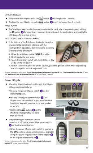
Power Liftgate
When the liftgate is closed and locked, the liftgate
will open automatically by:
•
Pushing the power liftgate switch 1 on the
instrument panel.
•
Pushing the liftgate opener switch 2, the
liftgate must be unlocked, or you must have the
Intelligent Key with you (that is, in your pocket
or purse).
•
Pressing the button
3 on the
INFINITI Intelligent Key for more
than 1 second.
The power liftgate operation can be
turned on or off by the power liftgate main switch
4 on the instrument panel.
•
When the power liftgate main switch is pushed to
the
OFF position, power operation is not available
using the power liftgate switch on the liftgate
5
or the liftgate opener switch 2.
For more information, refer to the “Pre-driving checks and adjustments
(section 3)” of your Owner’s Manual.
2
53
41
Page 14 of 36

12
first drive features
Power Seat Adjustments
To slide the seat forward or backward, push the
control switch
1 forward or backward. To recline the seatback, push the switch
2
forward or backward.
SEAT LIFTER
To raise or lower the front portion or height of the
seat, push the front or back end of the switch
1 up or down.
POWER LUMBAR SUPPORT (if so equipped for driver’s seat)
To adjust the seat lumbar support, push the front or back end of the swi\
tch 3.
For more information, refer to the “Safety —— Seats, seat belts and supplemental restraint system (section 1)”\
of your
Owner’s Manual.
2ND Row Seats
To slide the seat forward or backward, pull the
center of the bar
1 up and hold it while you slide
the seat forward or backward to the desired
position. Release the bar to lock the seat
in position.
To recline the seatback, pull up on the recline handle
2 and lean back. To bring the seatback forward, pull
the lever up and lean your body forward. Release the
lever to lock the seatback in position.
MULTI-MODE/CHILD SEAT ACCESS FUNCTION
This feature is not available on the driver’s side of the 2nd row seat.
If a child safety seat is installed on the passenger’s side of the 2nd row seat, the 3rd row
can be accessed without removing the child safety seat.
To access the 3rd row from outside the vehicle, lift up on the seatback release lever 3.
EZ ENTRY MODE
To enter the 3rd row from outside the vehicle, lift up fully on the seatback lever 3.
This will release the back of the seat and fold up the seat cushion.
For access to the rear seat, slide the entire seat forward by pushing on\
the u pper
seatback area.
To return the seat to a locked position, push the upper seatback rearwar\
d u ntil the
seatback and track are locked. Push the seat cushion down. Locking the s\
eatback will
also lock the track.
For more information, refer to the “Safety —— Seats, seat belts and supplemental restraint system (section 1)”\
of your Owner’s Manual.
123
12
3
Page 15 of 36

13
3RD Row Manual Reclining Seatback
To recline the seatback, pull up on the latch 1
located on the outside corner of each seatback.
Lean back until the desired angle is obtained.
To bring the seatback forward again, pull up on the
latch
1 and move your body forward. The
seatback will move forward.
For more information, refer to the “Safety —— Seats, seat belts and
supplemental restraint system (section 1)” of your Owner’s Manual.
Automatic Drive Positioner (if so equipped)
Two positions for the driver’s seat, steering column
and outside mirrors can be stored in the automatic
drive positioner
1 memory. Follow this procedure to set the memory positions:
•
Confirm the shift lever is in the
P (PARK) position.
•
Push the ignition switch to the
ON position.
• Adjust the driver’s seat, steering column and
outside mirrors to the desired positions using the adjusting switches fo\
r each feature.
•
Push the SET switch and within 5 seconds push the memory switch (1 or 2) for at least 1 second.
• The indicator light on the memory switch you select will illuminate for \
approximately 5
seconds, and a chime will sound (if so equipped) when the memory is st\
ored correctly.
•
The driver’s seat, steering column and outside mirror positions are n\
ow set to
your preferences.
These memorized positions can also be linked to your INFINITI Intelligen\
t Key. To link a
memorized position to your INFINITI Intelligent Key, press the UNLOCK button on the key fob
after completing the previous step.
For more information, refer to the “Pre-driving checks and adjustments (section 3)” of your Owner’s Manual.
Outside Mirror Control Switch
T o select the right or left side mirror, move the
control switch
1 right or left.
Adjust each mirror to the desired position using the
switch
2.
To fold the outside rearview mirrors, push the
switch
3 to the
position. To unfold the
outside rearview mirrors, push the switch
3 to
the
position.
2
1
3
1
1
Page 16 of 36

The reverse tilt-down feature will turn both outside mirror surfaces dow\
nward to provide
better rear visibility close to the v")
14
first drive features
REVERSE TILT-DOWN FEATURE (if so equipped)
The reverse tilt-down feature will turn both outside mirror surfaces dow\
nward to provide
better rear visibility close to the vehicle.
1.
Push the ignition switch to the
ON position.
2.
Choose the right or left outside mirror by operating the outside mirror \
control switch 1.
3.
Move the shift lever to the
R (REVERSE) position.
4.
The outside mirror surfaces move downward.
The outside mirror surfaces will return to their original position when \
one of the following
conditions has occurred:
•
The shift lever is moved to any position other than
R (REVERSE).
•
The outside mirror control switch is set to the center (neutral) posit\
ion.
•
The ignition switch is pushed to the
OFF position.
For more information, refer to the “Pre-driving checks and adjustments (section 3)” of your Owner’s Manual.
Starting/Stopping the Hybrid System
It is important to make sure the INFINITI Intelligent
Key is with you (that is, in your pocket or purse).
Depress the brake pedal.
Press the ignition switch START/STOP button to
start the hybrid system.
TURNING THE HYBRID SYSTEM OFF
Move the shift lever to the P (PARK) position and
apply the parking brake.
Press the ignition switch START/STOP button to turn the hybrid system off.
For more information, refer to the “Starting and driving (section 5)” of your Owner’s Manual.
Assist Charge Gauge
This shows the power consumed 2 or generated
1 by the electric motor.
For more information, refer to the “HEV Overview (section HEV)” and the
“Instruments and controls (section 2)” of your Owner’s Manual.12