2015 FORD F250 SUPER DUTY ignition
[x] Cancel search: ignitionPage 188 of 470
be: 635 kilograms - (2 x 99kilograms) - (12 x 45 kilograms) =635 - 198 - 540 = -103 kilograms.You will need to reduce the loadweight by at least 240 pounds(104 kilograms). If you removethree 100-pound (45-kilogram)cement bags, then the loadcalculation would be:1400 - (2 x220) - (9 x 100) = 1400 - 440 -900 = 60 pounds. Now you havethe load capacity to transport thecement and your friend home. Inmetric units, the calculation wouldbe: 635 kilograms - (2 x 99kilograms) - (9 x 45 kilograms) =635 - 198 - 405 = 32 kilograms.
The above calculations alsoassume that the loads arepositioned in your vehicle in amanner that does not overloadthe Front or the Rear Gross AxleWeight Rating specified for yourvehicle on the Safety ComplianceCertification Label. The label shallbe affixed to either the door hingepillar, door-latch post, or the dooredge that meets the door-latchpost, next to the driver's seatingposition.
Special Loading Instructionsfor Owners of Pick-up Trucksand Utility-type Vehicles
WARNING
Loaded vehicles may handledifferently than unloadedvehicles. Extra precautions, suchas slower speeds and increasedstopping distance, should betaken when driving a heavilyloaded vehicle.
Your vehicle can haul more cargoand people than most passengercars. Depending upon the typeand placement of the load,hauling cargo and people mayraise the center of gravity of thevehicle.
TAILGATE
Tailgate Lock
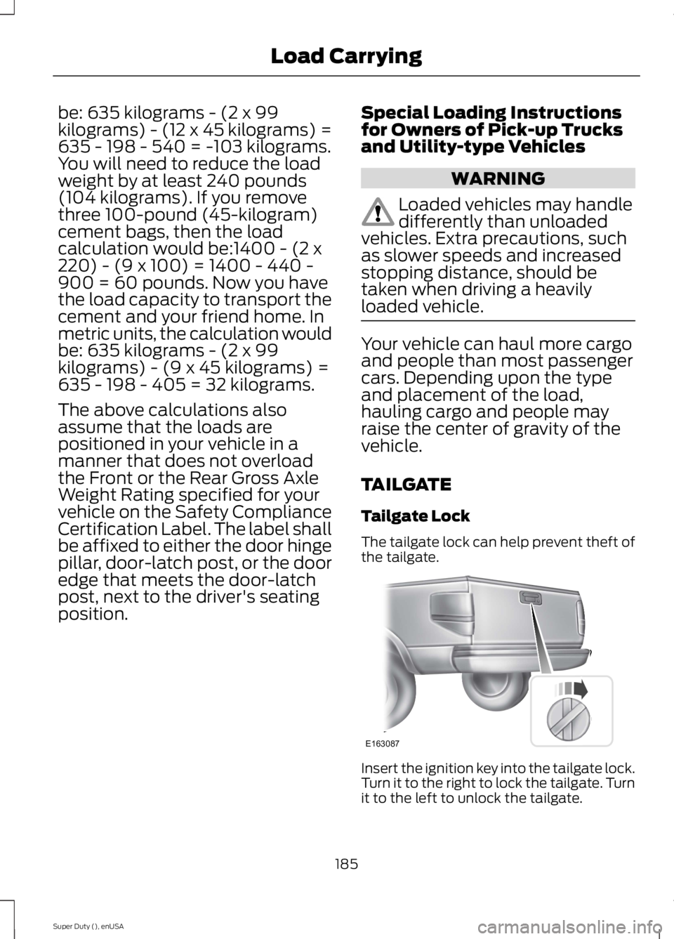
The tailgate lock can help prevent theft ofthe tailgate.
Insert the ignition key into the tailgate lock.Turn it to the right to lock the tailgate. Turnit to the left to unlock the tailgate.
185
Super Duty (), enUSA
Load CarryingE163087
Page 202 of 470
You can adjust the amount ofinitial trailer brake output byselecting one of three settingsthrough the message center.
Ford has tested the trailer brakecontroller to be compatible withseveral major brands ofelectric-over-hydraulic trailerbrakes. Contact an authorizeddealer for information on whichbrands you can use.
The controller user interfaceconsists of the following:
A: + and - (Gain adjustmentbuttons): Pressing these buttonsadjusts the controller's poweroutput to the trailer brakes in 0.5increments. You can increase thegain setting to 10.0 (maximumtrailer braking) or decrease it to 0(no trailer braking). Pressing andholding a button raises or lowersthe setting continuously. The gainsetting displays in the messagecenter as follows: TBC GAIN =XX.X.
B: Manual control lever: Slide thecontrol lever to the left to switchon the trailer's electric brakesindependent of the tow vehicle's.See the following Procedure foradjusting gain section forinstructions on proper use of thisfeature. If you use the manualcontrol while the brake is alsoapplied, the greater of the twoinputs determines the power sentto the trailer brakes.
•Stop lamps: Using the manualcontrol lever lights both thetrailer brake lamps and yourvehicle brake lamps except thecenter high-mount stop lamp,if you make the properelectrical connection to thetrailer. Pressing your vehiclebrake pedal also lights bothtrailer and vehicle brake lamps.
The controller shows gain setting,output bar graph, and trailerconnectivity status in theinformation display. They appearin the information display asfollows:
•TBC GAIN = XX.X NOTRAILER: Shows the currentgain setting during a givenignition cycle and when
adjusting the gain. This alsodisplays if you use the manualcontrol lever or make gainadjustments with no trailerconnected.
•TBC GAIN = XX.XOUTPUT=/ / / / / /: Displayswhen you push your vehicle'sbrake pedal, or upon use of themanual control. Bar indicatorslight in the information displayto indicate the amount ofpower going to the trailerbrakes relative to the brakepedal or manual control input.One bar indicates the leastamount of output; six barsindicate maximum output.
199
Super Duty (), enUSA
Towing
Page 203 of 470
•TRAILER CONNECTED:Displays when the systemsenses a correct trailer wiringconnection during a givenignition cycle.
•TRAILER DISCONNECTED:Displays, accompanied by asingle audible time, when thesystem senses a trailerconnection and then adisconnection, eitherintentional or unintentional,during a given ignition cycle. Italso displays if a truck ortrailer-wiring fault occurscausing the trailer to appeardisconnected. This messagecan also display if you use themanual control lever without atrailer connected.
Procedure for Adjusting Gain
Note:Only perform this procedurein a traffic-free environment atspeeds of approximately 20-25mph (30-40 km/h).
The gain setting sets the trailerbrake controller for the specifictowing condition. You shouldchange the setting as towingconditions change. Changes totowing conditions include trailerload, vehicle load, road conditionsand weather.
The gain should be set to providethe maximum trailer brakingassistance while making sure thetrailer wheels do not lock whenusing the brakes. Locked trailerwheels may lead to trailerinstability.
1.Make sure the trailer brakes arein good working condition,functioning normally andproperly adjusted. See yourtrailer dealer if necessary.
2.Hook up the trailer and makethe electrical connectionsaccording to the trailermanufacturer's instructions.
3.When you plug in a trailer withelectric orelectric-over-hydraulic brakes,TRAILER CONNECTEDappears in the informationdisplay.
4.Use the gain adjustment (+ and-) buttons to increase ordecrease the gain setting to thedesired starting point. A gainsetting of 6.0 is a good startingpoint for heavier loads.
5.In a traffic-free environment,tow the trailer on a dry, levelsurface at a speed of 20-25mph (30-40 km/h) andsqueeze the manual controllever completely.
6.If the trailer wheels lock up,indicated by squealing tires,reduce the gain setting. If thetrailer wheels turn freely,
increase the gain setting.Repeat Steps 5 and 6 until the
200
Super Duty (), enUSA
Towing
Page 206 of 470
•When you switch the engineoff, the controller output isdisabled and the display andmodule shut down. Thecontroller module and displayturn on when you switch theignition on.
•The trailer brake controller isonly a factory-installed ordealer-installed item. Ford isnot responsible for warranty orperformance of the controllerdue to misuse or customerinstallation.
Trailer Lamps
WARNING
Never connect any trailerlamp wiring to the vehicle'stail lamp wiring; this may damagethe electrical system resulting infire. Contact your authorizeddealer as soon as possible forassistance in proper trailer towwiring installation. Additionalelectrical equipment may berequired.
Trailer lamps are required on mosttowed vehicles. Make sure allrunning lights, brake lights, turnsignals and hazard lights areworking.
Using a Step Bumper (IfEquipped)
The rear bumper is equipped withan integral hitch and only requiresa ball with a one-inch (25.4millimeter) shank diameter. Thebumper has a 5000-pound (2268kilogram) trailer weight and a500-pound (227 kilogram) tongueweight capacity
If it is necessary to relocate thehitch ball position, you must installa frame-mounted trailer hitch.
Before Towing a Trailer
Practice turning, stopping andbacking up to get the feel of yourvehicle-trailer combination beforestarting on a trip. When turning,
make wider turns so the trailerwheels clear curbs and otherobstacles.
When Towing a Trailer
•Do not drive faster than 70mph (113 km/h) during the first500 miles (800 kilometers).
•Do not make full-throttlestarts.
•Check your hitch, electricalconnections and trailer wheel
lug nuts thoroughly after youhave traveled 50 miles (80kilometers).
203
Super Duty (), enUSA
Towing
Page 216 of 470
HAZARD WARNING FLASHERS
Note:The hazard warning flashers willoperate when the ignition is in any positionor if the key is not in the ignition. If usedwhen the engine is not running, the batterywill lose charge. As a result, there may beinsufficient power to restart your engine.
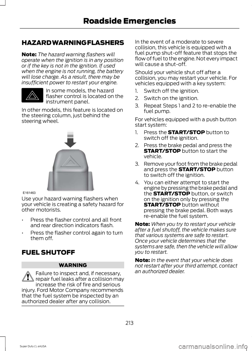
In some models, the hazardflasher control is located on theinstrument panel.
In other models, this feature is located onthe steering column, just behind thesteering wheel.
Use your hazard warning flashers whenyour vehicle is creating a safety hazard forother motorists.
•Press the flasher control and all frontand rear direction indicators flash.
•Press the flasher control again to turnthem off.
FUEL SHUTOFF
WARNING
Failure to inspect and, if necessary,repair fuel leaks after a collision mayincrease the risk of fire and seriousinjury. Ford Motor Company recommendsthat the fuel system be inspected by anauthorized dealer after any collision.
In the event of a moderate to severecollision, this vehicle is equipped with afuel pump shut-off feature that stops theflow of fuel to the engine. Not every impactwill cause a shut-off.
Should your vehicle shut off after acollision, you may restart your vehicle. Forvehicles equipped with a key system:
1. Switch off the ignition.
2. Switch on the ignition.
3. Repeat Steps 1 and 2 to re-enable thefuel pump.
For vehicles equipped with a push buttonstart system:
1. Press the START/STOP button toswitch off the ignition.
2. Press the brake pedal and press theSTART/STOP button to start thevehicle.
3.Remove your foot from the brake pedaland press the START/STOP buttonto switch off the ignition.
4. You can either attempt to start theengine by pressing the brake pedal andthe START/STOP button, or switchon the ignition only by pressing theSTART/STOP button withoutpressing the brake pedal. Both waysre-enable the fuel system.
Note:When you try to restart your vehicleafter a fuel shutoff, the vehicle makes surethat various systems are safe to restart.Once your vehicle determines that thesystems are safe, then the vehicle will allowyou to restart.
Note:In the event that your vehicle doesnot restart after your third attempt, contactan authorized dealer.
213
Super Duty (), enUSA
Roadside EmergenciesE142663 E161463
Page 233 of 470
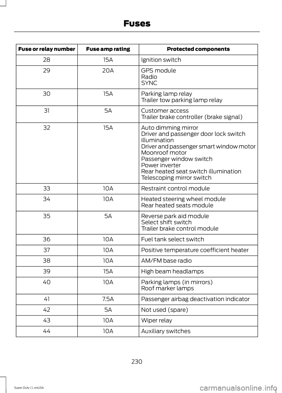
Protected componentsFuse amp ratingFuse or relay number
Ignition switch15A28
GPS module20A29RadioSYNC
Parking lamp relay15A30Trailer tow parking lamp relay
Customer access5A31Trailer brake controller (brake signal)
Auto dimming mirror15A32Driver and passenger door lock switchilluminationDriver and passenger smart window motorMoonroof motorPassenger window switchPower inverterRear heated seat switch illuminationTelescoping mirror switch
Restraint control module10A33
Heated steering wheel module10A34Rear heated seats module
Reverse park aid module5A35Select shift switchTrailer brake control module
Fuel tank select switch10A36
Positive temperature coefficient heater10A37
AM/FM base radio10A38
High beam headlamps15A39
Parking lamps (in mirrors)10A40Roof marker lamps
Passenger airbag deactivation indicator7.5A41
Not used (spare)5A42
Wiper relay10A43
Auxiliary switches10A44
230
Super Duty (), enUSA
Fuses
Page 249 of 470
control fan, heated steering wheel, audioand navigation system. A message may beshown in the information displays to alertthe driver that battery protection actionsare active. These messages are only fornotification that an action is taking place,and not intended to indicate an electricalproblem or that the battery requiresreplacement.
Electrical accessory installation
To ensure proper operation of the BMS,any electrical devices that are added tothe vehicle should not have their groundconnection made directly at the negativebattery post. A connection at the negativebattery post can cause inaccuratemeasurements of the battery conditionand potential incorrect system operation.
Note:Electrical or electronic accessoriesadded to the vehicle by the dealer or theowner may adversely affect batteryperformance and durability, and may alsoaffect the performance of other electricalsystems in the vehicle.
When a battery replacement is required,the battery should only be replaced witha Ford recommended replacement batterywhich matches the electrical requirementsof the vehicle. After battery replacement,or in some cases after charging the batterywith the external charger, the BMS requireseight hours of vehicle sleep time (key offwith doors closed) to relearn the newbattery state of charge. Prior to relearningthe state of charge, the BMS may disableelectrical features (to protect the battery)earlier than normal.
CHECKING THE WIPER
BLADES
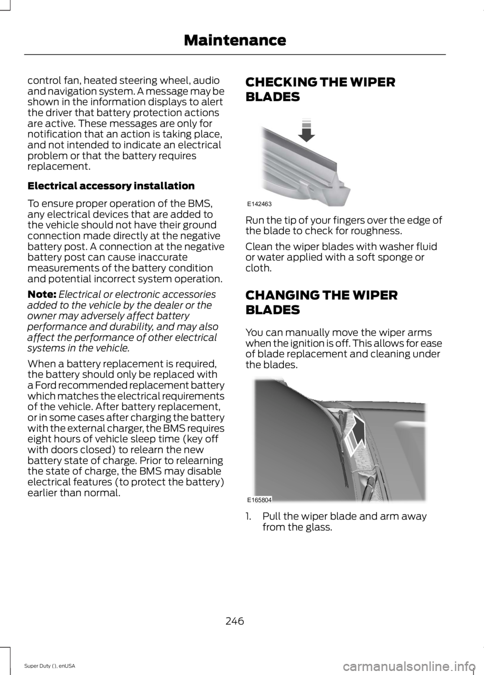
Run the tip of your fingers over the edge ofthe blade to check for roughness.
Clean the wiper blades with washer fluidor water applied with a soft sponge orcloth.
CHANGING THE WIPER
BLADES
You can manually move the wiper armswhen the ignition is off. This allows for easeof blade replacement and cleaning underthe blades.
1. Pull the wiper blade and arm awayfrom the glass.
246
Super Duty (), enUSA
MaintenanceE142463 E165804
Page 250 of 470
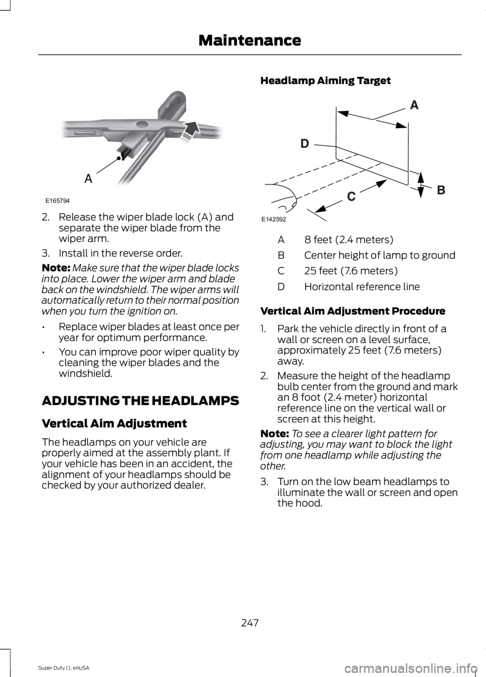
2. Release the wiper blade lock (A) andseparate the wiper blade from thewiper arm.
3. Install in the reverse order.
Note:Make sure that the wiper blade locksinto place. Lower the wiper arm and bladeback on the windshield. The wiper arms willautomatically return to their normal positionwhen you turn the ignition on.
•Replace wiper blades at least once peryear for optimum performance.
•You can improve poor wiper quality bycleaning the wiper blades and thewindshield.
ADJUSTING THE HEADLAMPS
Vertical Aim Adjustment
The headlamps on your vehicle areproperly aimed at the assembly plant. Ifyour vehicle has been in an accident, thealignment of your headlamps should bechecked by your authorized dealer.
Headlamp Aiming Target
8 feet (2.4 meters)A
Center height of lamp to groundB
25 feet (7.6 meters)C
Horizontal reference lineD
Vertical Aim Adjustment Procedure
1. Park the vehicle directly in front of awall or screen on a level surface,approximately 25 feet (7.6 meters)away.
2. Measure the height of the headlampbulb center from the ground and markan 8 foot (2.4 meter) horizontalreference line on the vertical wall orscreen at this height.
Note:To see a clearer light pattern foradjusting, you may want to block the lightfrom one headlamp while adjusting theother.
3. Turn on the low beam headlamps toilluminate the wall or screen and openthe hood.
247
Super Duty (), enUSA
MaintenanceA
E165794 E142592