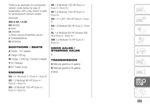
Page 177 of 323
DEVICE PROTECTED FUSE AMPERE
Heated driver seat F1 10
Heated passenger seat F2 10
Cigar lighterF3 15
Third power socket on dashboard F4 20
Driver's side rear electric window F5 20
Passenger's side rear electric window F6 20
IMPORTANT
26) Never replace a blown fuse with metal wires or other material.
27) If you need to wash the engine compartment, take care not to directly hit the fuse box and the window wiper motors
with the water jet.
173
Page 178 of 323
WARNING
105) If the replaced fuse blows again, contact a Fiat Dealership.
106) Never replace a fuse with another with a higher amp rating; DANGER OF FIRE. If a general protection fuse
(MEGA-FUSE, MIDI-FUSE) is activated, contact a Fiat Dealership. Before replacing a fuse, make sure that the ignition
key has been removed and that all the other services are switched off and/or disengaged.
107) Contact a Fiat Dealership if a safety system (airbags, brakes), engine system (engine, gearbox) or steering system
general protection fuse blows.
174
IN AN EMERGENCY
Page 179 of 323

CHANGING A WHEEL
The vehicle is originally equipped
with the Fix&Go automatic quick
tyre repair kit (see instructions in the
next section). As an alternative,
the vehicle may have a normal-sized
spare wheel.
Wheel changing and correct use of
the jack and spare wheel call for
some precautions, as listed below.
108) 109) 110) 111)
Note for one-way
tyres
One-way tyres have a few arrows on
the side indicating the rotation
direction. If a wheel is changed
(when punctured, for example) the
direction of the arrows on the spare
wheel tyre may not coincide with
the rotation direction of the wheel to
be replaced.
In these conditions, too, the tyre still
maintains its safety features.Anyway, it is recommended to have
the wheel repaired and refitted as
soon as possible, as the best
performance is achieved when the
rotation direction of all tyres
coincides with the one indicated by
the arrows.
Please note that:
❒the jack weight is 4 kg;
❒the jack requires no adjustment;
❒the jack cannot be repaired and in
the event of a fault it must be
replaced by another original one;
❒no tool other than its cranking device
may be fitted on the jack.
To change a wheel, proceed as
follows:
❒stop the vehicle in a position that is
not dangerous for oncoming traffic
where you can change the wheel
safely. The ground should be flat
if possible, and sufficiently firm;
❒stop the engine and pull the
handbrake;
❒engage first gear or reverse;
❒wear the reflective safety jacket
(compulsory by law in certain
countries) before getting out of the
vehicle;❒indicate that the vehicle has broken
down using the devices required by
the law in the current country (e.g.
warning triangle, hazard lights, etc.);
❒for Cargo versions fig. 180: move the
left front seat forward and operate
lever A to access the tool bag; take it
to the wheel that needs replacing;
❒for Doblò/Doblò Combi versions fig.
181: open the rear doors, inside the
compartment on the rear right side,
take the tool bag, unhooking the
elastic band from the buckle, and
take it next to the wheel to be
changed;
❒take wheel spanner B fig. 182 and
the extension with pentagonal fitting
C; inside the load area, fit extension
C on bolt A; use spanner B to lower
the wheel by unwinding the wire;
180F0V0149
175
Page 180 of 323
❒use the wheel dismantling spanner B
to remove the wheel from the vehicle
fig. 183;❒unscrew knob D fig. 184 and release
the rim from bracket E, removing it
from the hole of the rim;
❒for versions with alloy rims, remove
the press-fitted hub cap;
❒loosen the fixing bolts of the wheel to
be replaced by about one turn, using
the spanner provided;❒remove wedge D from the tool bag
and open it as shown in fig. 185;
❒place the wedge D behind the wheel
diagonally opposite the one you want
to replace fig. 186 to prevent the
vehicle from moving when it is raised.
181F0V0148
B
C
182F0V0150
183F0V0151
184F0V0193
185F0V0192
186F0V0153
176
IN AN EMERGENCY
Page 181 of 323

❒operate the jack using the knob
(release the handle from the clip and
the hole on the nut) in order to open
it partially fig. 187, then position it
under the vehicle in line with
references A fig. 188 near the wheel
to be changed.
❒operate the jack with the knob to
open it until the groove A fig. 189
of the jack is correctly inserted in the
lower profile B on the side member:❒warn anybody nearby that the vehicle
is about to be lifted. They must stay
clear and not touch the vehicle until it
is back on the ground.
❒introduce the handle in the hole on
the nut and the plastic clip, then
operate the jack and raise the
vehicle, until the wheel is a few
centimetres off the ground. When
turning the crank, ensure that it
rotates freely in order to avoid grazing
your hands against the ground. The
moving components of the jack
(screws and joints) can also cause
injuries: avoid touching them. If
you become soiled with the
lubricating grease, clean it off
thoroughly;
❒fully loosen the fixing bolts and
remove the wheel;❒make sure the contact surfaces
between spare wheel and hub are
clean so that the fastening bolts will
not come loose;
❒fit the standard wheel by inserting the
first bolt B fig. 190 two threads into
the hole closest to the inflation valve
A;
❒fit the hubcap, making sure that the
symbol
aligns with the inflation
valve, and then insert the other three
bolts.
❒tighten the bolts using the spanner
provided;
❒turn the jack handle to lower the
vehicle, and remove the jack;
187F0V0154
188F0V0155
189F0V0156
190F0V0157
177
Page 182 of 323

❒use the wrench provided to fully
tighten the bolts, passing alternately
from one bolt to the opposite one,
as per the numerical sequence
illustrated in fig. 191.
At the end of the
operation
❒fix bracket A fig. 192 to the wheel
after passing it through the hole,
insert the threaded pin into one of the
bolt holes and secure by tightening
knob B;
❒for vehicles with alloy rims take the
adapter D fig. 193 and fit the plastic
spacer C between the spring and the
flange of the bracket. The plastic fin
must be directed downwards and
perfectly coincide with the flange cut
part;❒fit the bracket E fig. 194 in the
adapter D, fit the pin in the hole and
fasten by the knob F;
❒position the wheel vertically and rest
the fitted adaptor on the inside of the
rim, then using the screws provided
fix the wheel to the adaptor, using the
socket wrench for the wheel nuts G
fig. 195. Tighten the screws with
the wheel removal wrench.
NOTE Use the spare wheel covering
bag to protect the replaced alloy
wheel.
❒Check that the position of the
replaced wheel under the platform is
correct (the lifting system is equipped
with a clutch to limit the end of the
stroke, incorrect positioning may
jeopardise safety;)
❒put the jack and the tools back in the
dedicated tool bag;
191F0V0158
192F0V0194
193F0V0214
194F0V0215
G
195F0V0216
178
IN AN EMERGENCY
Page 183 of 323

❒reposition the tool bag behind the left
side seat (Cargo versions) or, resting
the bottom of the bag against the
side panel, in the compartment inside
the rear right side (Doblò/Doblò
Combi versions).
WARNING
108) The spare wheel (where
provided) is specifically for your
vehicle. Therefore, it must not be
used on other models. Do not
use spare wheels of other models
on your vehicle. The spare wheel
must be used only in an
emergency. Use of the spare
wheel must kept to the minimum
necessary.109) Use your hazard lights, warning
triangle, etc. to show that your
vehicle is stationary according to
the regulations in force.
Passengers should get out of the
vehicle, particularly if it is heavily
loaded, and wait for the wheel
to be changed away from the
traffic. If you are on a slope or
uneven surface, place wedges or
other suitable objects under the
wheels to secure the vehicle.
Have the wheel repaired and
refitted as soon as possible. Do
not apply grease to the bolt
threads before assembly: they
might spontaneously unscrew.
110) Use the jack only to replace
wheels on the vehicle with which
it is supplied or on other vehicles
of the same model. Never use
the jack for other purposes, such
as lifting other models. Never
use the jack to carry out repairs
under the vehicle. Incorrect
positioning of the jack may cause
the lifted vehicle to fall. Do not
use the jack for loads higher than
those shown on the label.111) Incorrect hub cap assembly
may cause it to come off when the
vehicle is moving. Never tamper
with the inflation valve. Never
introduce tools of any kind
between rim and tyre. Check tyre
and spare wheel pressures
regularly, referring to the values
shown in the "Technical
specifications" section.
179
Page 184 of 323

FIX&GO automatic
QUICK TYRE REPAIR
KIT
The quick repair kit Fix&Go
automatic is contained in a suitable
bag inside the compartment on
the right rear side or, for Cargo
versions, under the passenger seat
(for versions with fixed or movable
seat), or in the glove compartment
(for versions with folding seat).
The quick tyre repair kit contains fig.
196:
❒bottle A containing sealer and fitted
with:
– filler tube B
– sticker C bearing the notice “max.
80 km/h”, to be placed in a position
visible to the driver (on the
instrument panel) after fixing the tyre
❒compressor D complete with
pressure gauge and connectors.
❒instruction brochure (see fig. 197), to
be used for prompt and correct use
of the quick tyre repair kit and then to
be handed to the personnel charged
with handling the tyre treated with
the tyre repair kit
❒a pair of protective gloves located in
the side compartment of the
compressor
❒adaptors for inflating different
elements.
112)
28)
IMPORTANT
INFORMATION:
The sealing fluid of the quick tyre
repair kit is effective with external
temperatures between -20°C and
+50°C.
2)
113) 114) 115) 116)
INFLATION
PROCEDURE
117)
❒Pull the handbrake. Unscrew the tyre
valve cap, take out the filler hose A
fig. 198 and tighten the ring nut B on
the tyre valve;
196F0V0093
197F0V0094
198F0V0095
180
IN AN EMERGENCY