2015 BMW I8 warning
[x] Cancel search: warningPage 131 of 224

Desired speedThe desired speed is displayed next to
the symbol in the info display.▷The indicator lights up green: the
system is active.▷The indicator lights up orange: the system
has been interrupted.▷No display: system is switched off.
Brief status display
Selected desired speed.
If --- appears briefly on the display for Check
Control messages, it is possible that the sys‐
tem requirements are currently not ready for
operations.
Displays in the Head-up Display Some system information can also be dis‐played in the Head-up Display.
PDC Park Distance Control
The concept PDC is a support when parking. When you
slowly approach an object in the rear - or also
in the front of the vehicle if the feature is availa‐
ble - then the object is reported through:
▷Signal tones.▷Visual display.
General information
Ultrasound sensors in the bumpers measure
the distances from objects.
The maneuvering range, depending on the ob‐
stacle and environmental conditions, is approx.
6 ft/2 m.
An acoustic warning is first given:
▷By the front sensors and the two rear cor‐
ner sensors at approx. 24 in/60 cm.▷By the rear middle sensors at approx.
5 ft/1.50 m.
To ensure full functionality:
▷Do not cover sensors, e.g., with stickers,
bicycle racks.▷Keep the sensors clean and free of ice.▷When using high-pressure washers, do not
spray the sensors for long periods and
maintain a distance of at least 12 in/30 cm.
Hints
Personal responsibility
Even an active system does not relieve
the driver from personal responsibility while
driving.
Technically the system has its limits, it cannot
independently react to all traffic situations.
Monitor your driving, be on the alert, observe
the vehicle surroundings and other traffic and
react when needed - risk of accident.◀
Avoid driving fast with PDC
Avoid approaching an object too fast.
Avoid driving off fast while PDC is not yet ac‐
tive.
For technical reasons, the system may other‐
wise be too late in issuing a warning.◀
Overview
With front PDC: button in vehicle
PDC Park Distance Control
Seite 115Driving comfortControls115
Online Edition for Part no. 01 40 2 960 891 - II/15
Page 132 of 224

Switching on/off
Switching on automatically PDC switches on automatically in the following
situations:▷If selector lever position R is engaged while
the engine is running or in electric mode.
The rearview camera also switches on.▷If equipped with front PDC: when obsta‐
cles are detected behind or in front of the
vehicle by PDC and the speed is slower
than approx. 2.5 mph/4 km/h.
You may turn off automatic activation:
1."Settings"2."Parking"3.Select setting.
Settings are stored for the profile currently
in use.
Automatic deactivation during forward
travel
The system switches off when a certain driving
distance or speed is exceeded.
Switch the system back on if needed.
With front PDC: switching on/off
manually
Press button.
▷On: the LED lights up.▷Off: the LED goes out.
The rearview camera image is displayed when
the reverse gear is engaged by pressing the
button.
Display
Signal tones When approaching an object, an intermittent
sound indicates the position of the object. E. g.
if an object is detected to the left rear of the
vehicle, a signal tone sounds from the left rear
speaker.
The shorter the distance to the object, the
shorter the intervals.
If the distance to a detected object in the front
is less than approx. 12 in/30 cm and in the rear
less than approx. 20 in/50 cm, a continuous
tone is sounded.
With front PDC: if objects are located both in
front of and behind the vehicle, an alternating
continuous signal is sounded.
The signal tone is switched off, when selector
lever position P is engaged on vehicles with
Steptronic transmission.
Volume
The volume of the PDC signal tone can be ad‐
justed similar to the sound and volume set‐
tings of the radio.
Settings are stored for the profile currently in
use.
Visual warning
The approach of the vehicle to an object can
be shown on the Control Display. Objects that
are farther away are already displayed on the
Control Display before a signal sounds.
A display appears as soon as Park Distance
Control (PDC) is activated.
The range of the sensors is represented in the
colors green, yellow and red.
When the image of the rearview camera is dis‐
played, the reel can be made to PDC:
"Rear view camera"
System limits
Limits of ultrasonic measurement
Ultrasonic measuring might not function under
the following circumstances:
▷For small children and animals.Seite 116ControlsDriving comfort116
Online Edition for Part no. 01 40 2 960 891 - II/15
Page 133 of 224

▷For persons with certain clothing, e.g.
coats.▷With external interference of the ultra‐
sound, e.g. from passing vehicles or loud
machines.▷When sensors are dirty, iced over, dam‐
aged or out of position.▷Under certain weather conditions such as
high relative humidity, rain, snowfall, ex‐
treme heat or strong wind.▷With tow bars and trailer couplings of other
vehicles.▷With thin or wedge-shaped objects.▷With moving objects.▷With elevated, protruding objects such as
ledges or cargo.▷With objects with corners and sharp edges.▷With objects with a fine surface structure
such as fences.▷For objects with porous surfaces.
Low objects already displayed, e.g., curbs, can
move into the blind area of the sensors before
or after a continuous tone sounds.
False warnings
PDC may issue a warning under the following conditions even though there is no obstacle
within the detection range:
▷In heavy rain.▷When sensors are very dirty or covered
with ice.▷When sensors are covered in snow.▷On rough road surfaces.▷On uneven surfaces, such as speed
bumps.▷In large buildings with right angles and
smooth walls, e.g., in underground ga‐
rages.▷In automatic car washes.▷Through heavy pollution.▷Due to other ultrasound sources, e.g.,
sweeping machines, high pressure steam
cleaners or neon lights.
Malfunction
A Check Control message is displayed.
Red symbol is displayed, and the range
of the sensors is dimmed on the Con‐
trol Display.
PDC has failed. Have the system checked.
To ensure full functionality:
▷Keep the sensors clean and free of ice.▷dimmedDo not put any stickers on sen‐
sors.▷When using high-pressure washers, do not
spray the sensors for long periods and
maintain a distance of at least 12 in/30 cm.
Surround View
The concept Surround View comprises various camera as‐
sistance systems that help the driver when
parking, maneuvering, and at complex exits
and intersections.
▷Rearview camera, refer to page 117▷Top View, refer to page 120.▷Side View, refer to page 122.
Rearview camera
The concept The rearview camera provides assistance in
parking and maneuvering backwards. The area
behind the vehicle is shown on the Control
Display.
Seite 117Driving comfortControls117
Online Edition for Part no. 01 40 2 960 891 - II/15
Page 139 of 224

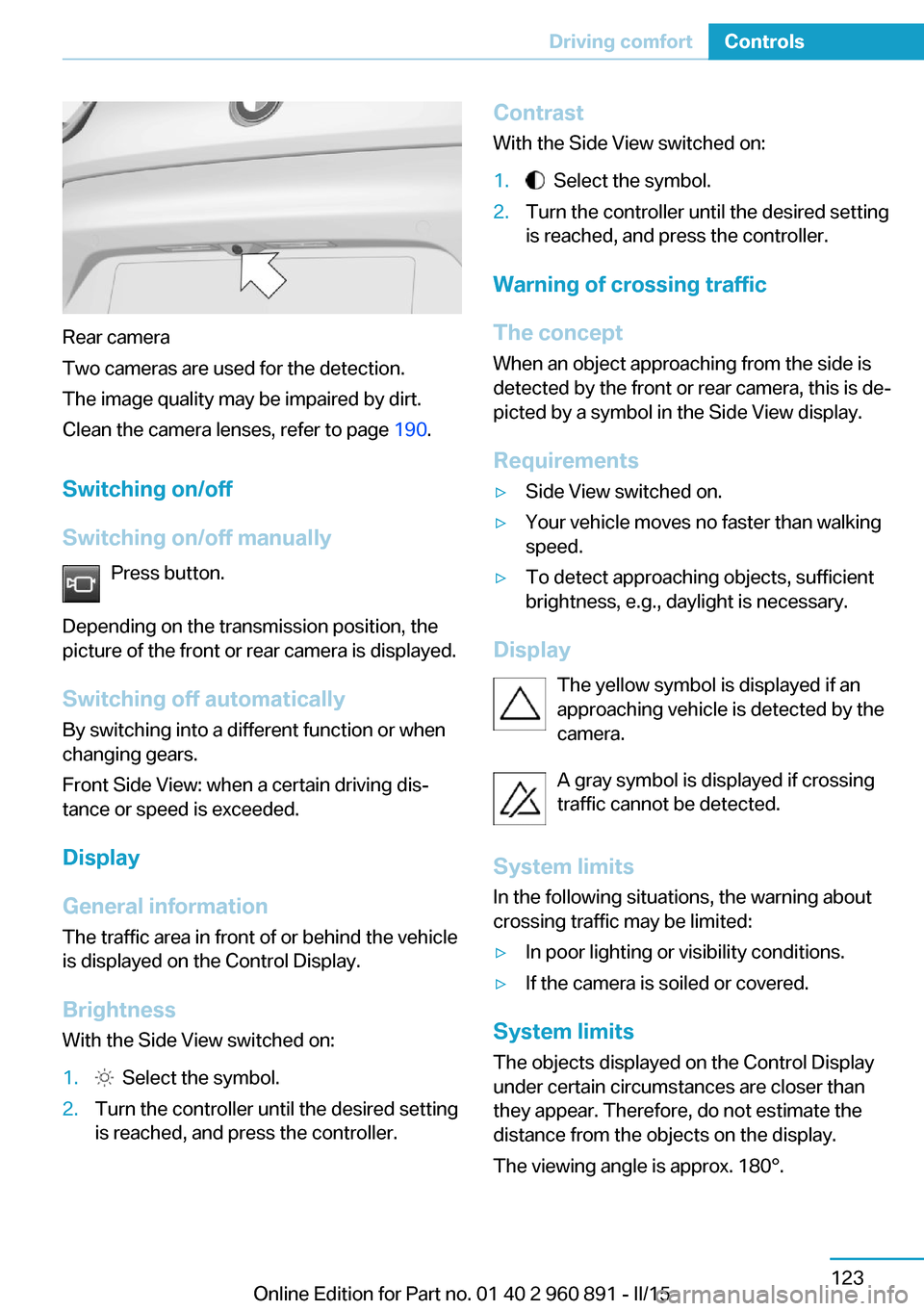
Rear camera
Two cameras are used for the detection.
The image quality may be impaired by dirt.
Clean the camera lenses, refer to page 190.
Switching on/off
Switching on/off manually Press button.
Depending on the transmission position, the
picture of the front or rear camera is displayed.
Switching off automatically By switching into a different function or when
changing gears.
Front Side View: when a certain driving dis‐
tance or speed is exceeded.
Display
General information
The traffic area in front of or behind the vehicle
is displayed on the Control Display.
Brightness With the Side View switched on:
1. Select the symbol.2.Turn the controller until the desired setting
is reached, and press the controller.Contrast
With the Side View switched on:1. Select the symbol.2.Turn the controller until the desired setting
is reached, and press the controller.
Warning of crossing traffic
The concept When an object approaching from the side is
detected by the front or rear camera, this is de‐
picted by a symbol in the Side View display.
Requirements
▷Side View switched on.▷Your vehicle moves no faster than walking
speed.▷To detect approaching objects, sufficient
brightness, e.g., daylight is necessary.
Display
The yellow symbol is displayed if anapproaching vehicle is detected by the
camera.
A gray symbol is displayed if crossing
traffic cannot be detected.
System limits
In the following situations, the warning about
crossing traffic may be limited:
▷In poor lighting or visibility conditions.▷If the camera is soiled or covered.
System limits
The objects displayed on the Control Display
under certain circumstances are closer than
they appear. Therefore, do not estimate the
distance from the objects on the display.
The viewing angle is approx. 180°.
Seite 123Driving comfortControls123
Online Edition for Part no. 01 40 2 960 891 - II/15
Page 161 of 224

Switch off any functions that
are not currently needed
Functions such as seat heating and the rear
window defroster require a lot of energy and
reduce the range, especially in city and stop-
and-go traffic.
Reel off these functions if they are not needed.
The ECO PRO driving program supports the
energy conserving use of comfort features.
These functions are automatically deactivated
partially or completely.
Have maintenance carried
out
Have vehicles maintained regularly to achieve
optimal vehicle efficiency and operating life.
The maintenance should be carried out by
your service center.
Also note the BMW Maintenance System, refer
to page 178.
ECO PRO
The concept
ECO PRO supports a driving style that saves
on fuel consumption. For this purpose, the en‐
gine control and comfort features, e. g. the cli‐
mate control output, are adjusted.
Under certain conditions the engine is auto‐
matically decoupled from the transmission in
the D selector lever position and the engine is
switched off. Selector lever position D remains
engaged.
At a glance
ECO PRO▷Reduce heat output or heating cycle for ex‐
terior mirror, rear window and seat heating.▷What reduces the the cooling and heating
output of the climate control system.
Activate ECO PRO
Press button repeatedly until ECO
PRO is displayed in the instrument
cluster.
Configuring ECO PRO
Via the Driving Dynamics Control
1.Activate ECO PRO.2."Configure ECO PRO"3.Configure the program.
Via the iDrive
1."Settings"2."ECO PRO mode"
Or
1."Settings"2."Driving mode"3."Configure ECO PRO"
Configure the program.
ECO PRO Tip
▷"Limit at:":
Adjust the ECO PRO speed.▷"ECO PRO speed warning":
The output is reduced once the set ECO
PRO speed is reached.
ECO PRO climate control
"ECO PRO climate control"
Climate control is set to be fuel-efficient.
By making a slight change to the set tempera‐
ture, or slowly adjusting the rate of heating or
cooling of the car's interior, fuel consumption
can be economized.
Seite 145Increase rangeDriving tips145
Online Edition for Part no. 01 40 2 960 891 - II/15
Page 191 of 224

Attaching the covers1.Insert, arrows 1, press down, arrows 2, and
push in, arrow 3 engine compartment
cover. Turn screws clockwise to tighten.2.Insert insulation.3.Insert cargo cover, and turn screws clock‐
wise to tighten.
Adding engine oil
General information
Switch off operating readiness and safely park
the vehicle before engine oil is added.
Hints Adding engine oil
Add oil within the next 125 miles/200 km;
otherwise, this may cause engine damage.◀
Do not add too much engine oil
When too much engine oil is added, im‐
mediately have the vehicle checked, otherwise,
this may cause engine damage.◀
Protect children
Keep oil, grease, etc., out of reach of chil‐
dren and observe the warnings on the contain‐
ers to prevent health risks.◀
Oil filler neck
The oil filler neck is located in the engine com‐
partment. Engine compartment access, refer
to page 174.
Only add engine oil when the message is dis‐
played in the instrument cluster. The quantity
to be added is indicated in the message dis‐
played in the instrument cluster.
Engine oil types to add Hints No oil additives
Oil additives may lead to engine dam‐
age.◀
Viscosity grades for engine oils
When selecting an engine oil, ensure that
the engine oil belongs to one of the viscosity
grades SAE 0W-40, SAE 0W-30, SAE 5W-40,
and SAE 5W-30 or malfunctions or engine
damage may occur.◀
The engine oil quality is critical for the life of
the engine.
Suitable engine oil types You can add engine oils that meet the follow‐
ing oil rating standards:
Gasoline engineBMW Longlife-01.BMW Longlife-01 FE.
Further information regarding the oil specifica‐
tions and viscosities of engine oils can be in‐
quired with the service center.
Seite 175Engine oilMobility175
Online Edition for Part no. 01 40 2 960 891 - II/15
Page 195 of 224

Service and Warranty
Information Booklet for US
models and Warranty and
Service Guide Booklet for
Canadian models
Please consult your Service and Warranty In‐
formation Booklet for US models and Warranty
and Service Guide Booklet for Canadian mod‐
els for additional information on service re‐
quirements.
Maintenance and repair should be performed
by your service center. Make sure to have reg‐
ular maintenance procedures recorded in the
vehicle's Service and Warranty Information
Booklet for US models, and in the Warranty
and Service Guide Booklet for Canadian mod‐
els. These entries are proof of regular mainte‐
nance.
Socket for OBD Onboard
Diagnosis
Note Socket for Onboard Diagnosis
The socket for onboard diagnostics may
only be used by the service center or a work‐
shop that operates in accordance with the
specifications of the vehicle manufacturer with
correspondingly trained personnel and other
authorized persons. Otherwise, use may result
in operating problems for the vehicle.◀Position
There is an OBD socket on the driver's side for
checking the primary components in the vehi‐
cle's emissions.
Emissions
▷The warning lamp lights up:
Emissions are deteriorating. Have
the vehicle checked as soon as
possible.▷The warning lamp flashes under certain
circumstances:
This indicates that there is excessive mis‐
firing in the engine.
Reduce the vehicle speed and have the
system checked immediately; otherwise,
serious engine misfiring within a brief pe‐
riod can seriously damage emission con‐
trol components, in particular the catalytic
converter.Seite 179MaintenanceMobility179
Online Edition for Part no. 01 40 2 960 891 - II/15
Page 199 of 224

Breakdown assistanceVehicle features and options
This chapter describes all standard, country-
specific and optional features offered with the
series. It also describes features that are not
necessarily available in your car, e. g., due to
the selected options or country versions. This
also applies to safety-related functions and
systems. The respectively applicable country
provisions must be observed when using the
respective features and systems.
Hazard warning flashers
The button is located in the center console.
Intelligent Emergency
Request
The concept In case of an emergency, an Emergency Re‐
quest can be made through this system.
General information
Only press the SOS button in an emergency.
Hints
Emergency Request not guaranteed
For technical reasons, the Emergency
Request cannot be guaranteed under unfavor‐
able conditions.◀
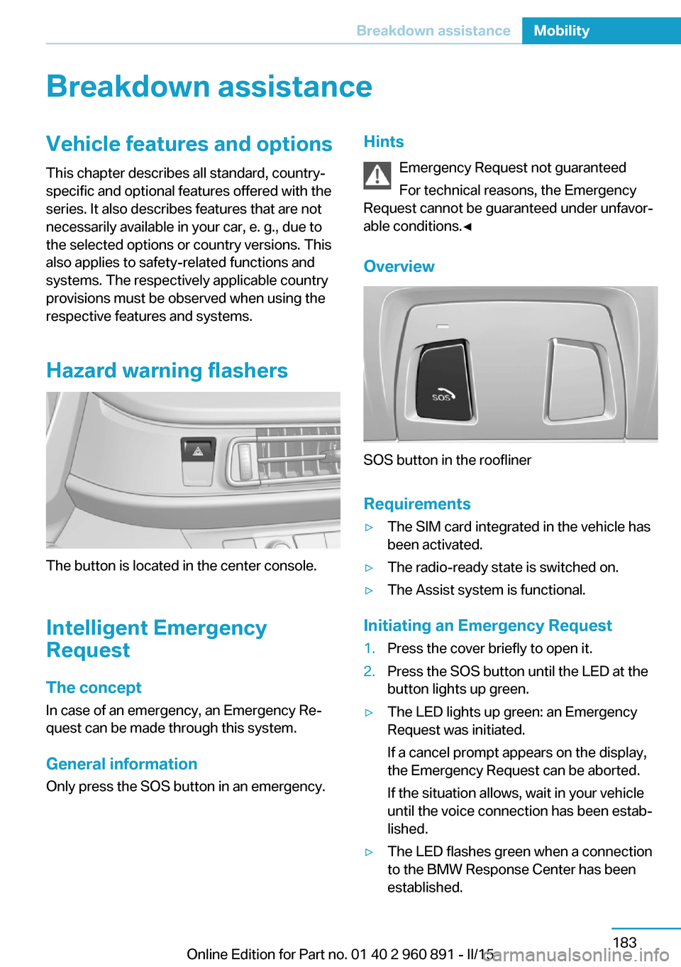
Overview
SOS button in the roofliner
Requirements
▷The SIM card integrated in the vehicle has
been activated.▷The radio-ready state is switched on.▷The Assist system is functional.
Initiating an Emergency Request
1.Press the cover briefly to open it.2.Press the SOS button until the LED at the
button lights up green.▷The LED lights up green: an Emergency
Request was initiated.
If a cancel prompt appears on the display,
the Emergency Request can be aborted.
If the situation allows, wait in your vehicle
until the voice connection has been estab‐
lished.▷The LED flashes green when a connection
to the BMW Response Center has been
established.Seite 183Breakdown assistanceMobility183
Online Edition for Part no. 01 40 2 960 891 - II/15