2015 AUDI S3 SEDAN ECO mode
[x] Cancel search: ECO modePage 4 of 282

Table of contents
Owner's Literature
About this Owner's Manual ... .. .
Cockpi t ... ...... ........... .. .. .. .
Cockpi t overview .......... .. .. .. .
Controls at a g lance . ..... ... .. .. .. .. .
Instrument s and indicator lights
Instruments .. .. ........... .. .. .. .. .
I ndicator ligh ts .... ..... ... .. .. .. .. .
On-Board Diagnostic system (OBD) ..... .
Driver inform ation system ..... .
Overview ..... .. ... .. ..... ... .. .. .. .
Operation . ..... .. . .. ..... ... .. .. .. .
Boost indicator .... ........... .. .. .. .
Efficiency program ............ .. .. .. .
Lap t imer a nd engine oil temperature
i n dicator . .. .... .......... ...... ... .
Start and drive .............. .. .. .
Opening and clo sing ...... .. .. .. .
Centra l locking .. .............. ... .. .
L uggage compa rtment lid .. .. .. .. .. .. .
Ch ild safety loc k ... ......... .. .. .. .. .
P ower windows . ............. .. .. .. .
P anorama s unroof .. ..... ... .. .. .. .. .
5
6
8
8
8
10
10
13
25
27
27
28
29
29
30
33
33
33
39
4 0
40
42
Light and Vi sion . . . . . . . . . . . . . . . . . . 43
Exterior lighting . . . . . . . . . . . . . . . . . . . . . 4 3
Interior lighting . . . . . . . . . . . . . . . . . . . . . 46
V1s1on . . . . . . . . . . . . . . . . . . . . . . . . . . . . . 4 7
W indshield wipers . . . . . . . . . . . . . . . . . . . 49
Dig ita l compass . . . . . . . . . . . . . . . . . . . . .
51
Seats and storage ....... .. .. ... . .
General information .......... .. .. .. .
53
53
Front seats . . . . . . . . . . . . . . . . . . . . . . . . . 54
H ead rest raints . . . . . . . . . . . . . . . . . . . . . 56
Socket . . . . . . . . . . . . . . . . . . . . . . . . . . . . . 57
S to rag e . . . . . . . . . . . . . . . . . . . . . . . . . . . . 58
L uggage compa rtmen t . . . . . . . . . . . . . . . 59
Roof rac k . . . . . . . . . . . . . . . . . . . . . . . . . .
6 2
Warm and cold . . . . . . . . . . . . . . . . . . . 64
Climate con trol sy stem . . . . . . . . . . . . . . . 6 4
2
Driving . . . . . . . . . . . . . . . . . . . . . . . . . . . . 70
General information . . . . . . . . . . . . . . . . . 70
Econom ica l and envi ronmentally-friendly
driving . . . . . . . . . . . . . . . . . . . . . . . . . . . . 70
Steering . . . . . . . . . . . . . . . . . . . . . . . . . . . 72
Starting and stopp ing the engine
(ve hicles w ith an ign ition lock) . . . . . . . . . 73
Start ing and stopp ing the engine
(ve hicl es w ith a convenience key) . . . . . . . 75
Drive r messages . . . . . . . . . . . . . . . . . . . . . 7 7
E lectromechanica l pa rking brake . . . . . . . 78
Hill ho ld . . . . . . . . . . . . . . . . . . . . . . . . . . . 80
Automatic tran smission . . . . . . . . . 82
S troni c . . . . . . . . . . . . . . . . . . . . . . . . . . . . 8 2
Trailer mode . . . . . . . . . . . . . . . . . . . . . . 91
Driving with a trailer . . . . . . . . . . . . . . . . . 91
Trai ler mode notes . . . . . . . . . . . . . . . . . . . 92
Driver assi stance . . . . . . . . . . . . . . . . . 9 4
Assi st .. .. .. .... .. .. ... .. ..... ... .. 94
E lectronic speed limiter* . . . . . . . . . . . . . . 94
Speed warning system . . . . . . . . . . . . . . . . 94
Cruise contro l system . . . . . . . . . . . . . . . . 94
Audi adaptive cruise control . . . . . . . . . . .
96
Audi pre sense . . . . . . . . . . . . . . . . . . . . . . 103
General informa tion . . . . . . . . . . . . . . . . . 103
Audi pr e sense bas ic . . . . . . . . . . . . . . . . . . 103
Audi pre se nse front. . . . . . . . . . . . . . . . . . 10 4
Driver messages . . . . . . . . . . . . . . . . . . . . . 106
Audi active lane assist . . . . . . . . . . . . . . . . 106
Audi s ide ass ist . . . . . . . . . . . . . . . . . . . . . 109
A udi drive select (d rive settings) . . . . . . . . 112
Parking systems
General information
Rear par king system
115
115
116
Parking system pl us. .. ........... .. .. 116
Rearv iew camera . . . . . . . . . . . . . . . . . . . . 117
Page 11 of 282

M N
0 > co ...... \!) ..,.,
..,.,
..,., ......
CD
@
®
©
®
®
(J)
®
Power windows
Door hand le
Aud i side assist
........ .... .. .
Centra l locking switch ... .. .. .. .
Powe r exter ior mir ro r adjustment
H ead light cont rol swit ch .. .. .. .
Vents
L ever fo r:
- Turn si gnals and high beams . . .
- Audi act ive lane assis t ... .. .. .
® Steer ing whee l w ith horn and
@
©
@
- Driver's airbag ....... .. .. .. .
- On-board computer controls .. .
- MMI, telephone , nav igat ion and
vo ice recogn ition system controls
- tiptron ic shift paddles (automatic
transmission)
I ns trumen t clus te r ..... .. .. .. .
W indshield washer system lever .
Steer ing column with:
- Ignit ion emergency operation (in
vehicles with conve nience key) .
- Ignit ion loc k (in vehicles wi th me-
chanical key) . ..... ... .. .. .. .
@ Adjustable steer ing column
(B) D epending on equipment: 4
0
109
37
47
4 3
64
45
106
152 28
87
1 0
49
7 7
73
72
- Cruise contro l lever . . . . . . . . . . 94
- adaptive cruise cont ro l . .. .. .. .
Driver's knee a irbag .... .. .. .. .
I ns trumen t illum ination . .. .. .. .
Hood re lease
. .. .... ... .. .. .. .
Luggage compartment release ..
C hild safety loc k bu tton . .. .. .. .
MMI disp lay (navigation, radio, TV/
video)
Glove compartment ( lockable) .. .
F ront passenger's airbag . ... .. .
Treble speakers Fr ont passenger's knee airbag .. .
Depending on equipment, b uttons
f or:
- Audi dr ive select ...... .. .. .. .
- Pa rking aid plus (o r with rearview
camera) 9
6
164
4 7
199
39
40
58
152
164
1 12
1 16
Co ckpit over view
-Eme rgency flashers ..... ... . .
- Elect ron ic St abiliza tion Control
( E SC) ..... .. .. .... .... ... . .
- MMI Displ ay
- Airbag Off indicato r ..... .... .
@ Depending on eq uipment:
- Manual climate contro l system .
- Automatic climate control
system ... .. ............. . .
@ Socket . .... .. .. ........... . .
S tronic se lector lever
. .... ... ..
Cup ho lde r .. .. .......... .... .
MM I On/ Off button
MMI control panel
Parking bra ke
@) I S TAR T ENGI NE STOPI button
(vehicles with convenie nce key)
(J} Tips
- Some the eq uipment listed here is only in
sta lled in certa in models or is available as
an option . 44
123
160
6S
66
5 7
82
58
78
75
- Ope rat ion of the Multi Med ia In terface
(MMI) is described in a separate o perating
instructions manual. You can a lso find infor
mation on A udi connect there.
9
Page 13 of 282
M N
0 > co ,...., \!) 1.1'1
1.1'1
1.1'1
,....,
Tachometer
The tachometer shows the number of engine rev
olutions per minutes .
The beginning of the red zone in the tachometer
indicates the maximum permissible engine speed
for all gears once the engine has been broken in
and when it is warm. You should select the "0/
S" (Drive) selector leve r position or take your foot
off the accelerator pedal before reach ing th is
area.
It is best to avoid high engine speeds, even when
driving in tiptronic mode
<=> page 87.
(D Note
The tachometer needle © c::> page 10, fig. 3
should only be in the red zone briefly:
@ For the sake of the environment
Upshifting early helps you to save fuel and re
duce operating noise .
Odometer
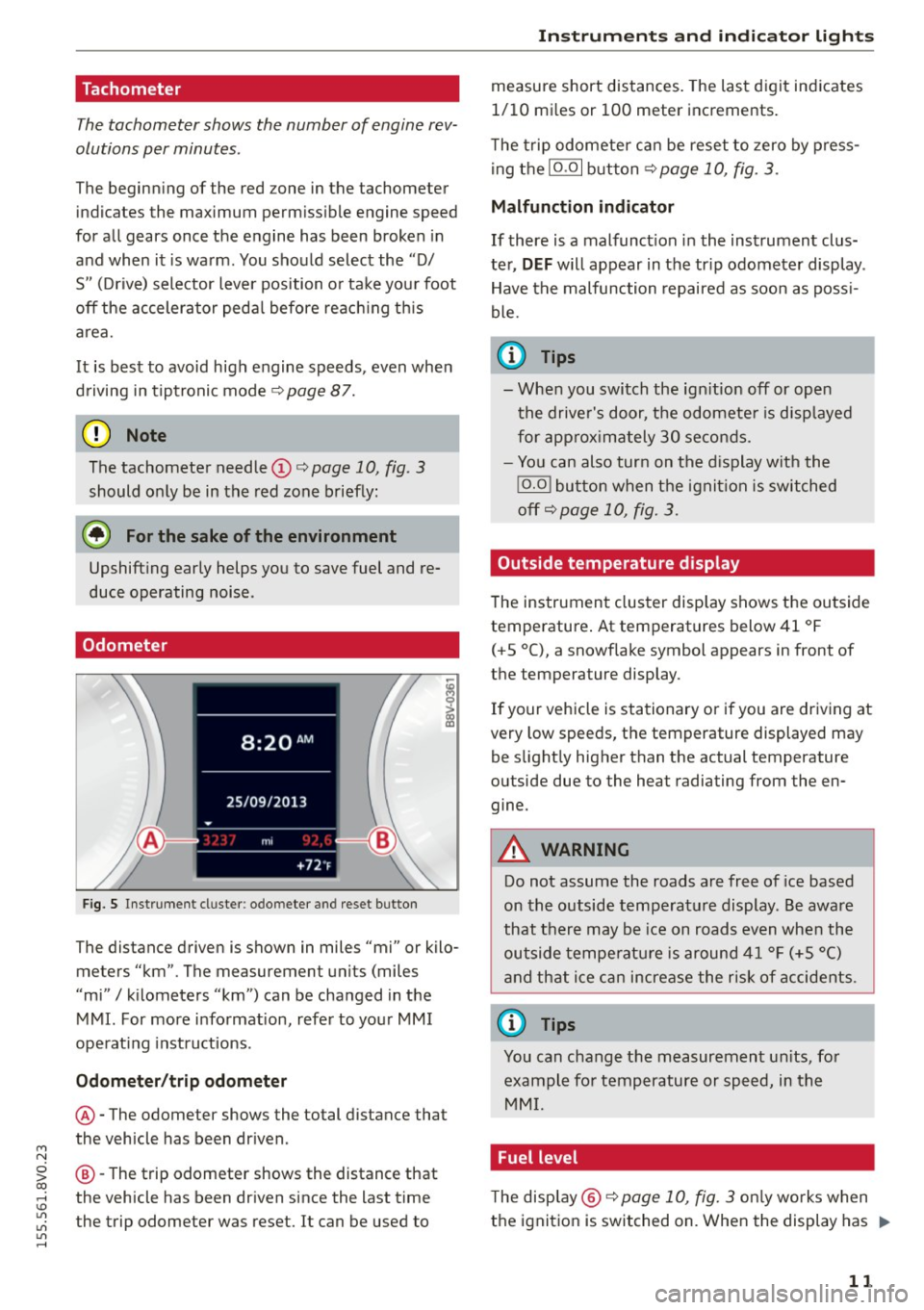
Fig. S Instrument cluster : odo meter and reset button
The distance driven is shown in miles "mi" or kilo
meters "km". The measuremen t units (miles
"mi"
I kilometers "km") can be changed in the
MMI. For more information, refer to your MMI
operat ing instructions .
Odometer/trip odometer
@-The odometer shows the total distance that
the vehicle has been driven .
@-The trip odometer shows the distance that
the vehicle has been driven since the last time
the trip odometer was reset. It can be used to
Instruments and indicator lights
measure short distances. The last digit indicates
1/10 mi les or 100 meter increments.
T he trip odometer can be reset to zero by press
ing the
10.01 button <=> page 10, fig . 3.
Malfunction indicator
If there is a malfunct ion in the instrument clus
ter,
DEF will appear in the tr ip odometer display .
Have the malfunction repaired as soon as poss i
ble.
@ Tips
- When you switch the ign ition off or open
the driver's door, the odometer is disp layed
for approximately 30 seconds.
- You can also turn on the display with the
!O .O I button when the ignition is switched
off c::>
page 10, fig. 3.
Outside temperature display
The instrument cluster display shows the outside
temperature . At temperatures below 41 °F
(+ S °C), a snowflake symbol appears in front of
the temperature display .
If your vehicle is stationary or if you are driving at
very low speeds, the temperature displayed may
be slightly higher than the actual temperature
outside due to the heat radiating from the en
gine.
A WARNING
-Do not assume the roads are free of ice based
on the outside temperature display. Be aware
that there may be ice on roads even when the
outside temperature is around 41 °F (+5 °()
and that ice can increase the risk of accidents.
@ Tips
You can change the measurement un its, for
example for temperature or speed, in the
MMI.
Fuel level
The display @ c::>page10, fig. 3 on ly works when
the ignition is switched on. When the display has .,.
11
Page 32 of 282
Driver information system
program is deleted ¢page 29, the values in the
on-board computer 1 are also reset.
Other equipment
Applies to vehicles: with driver information system
Fig. 13 Instrument cluster: Other equ ipment (examp le)
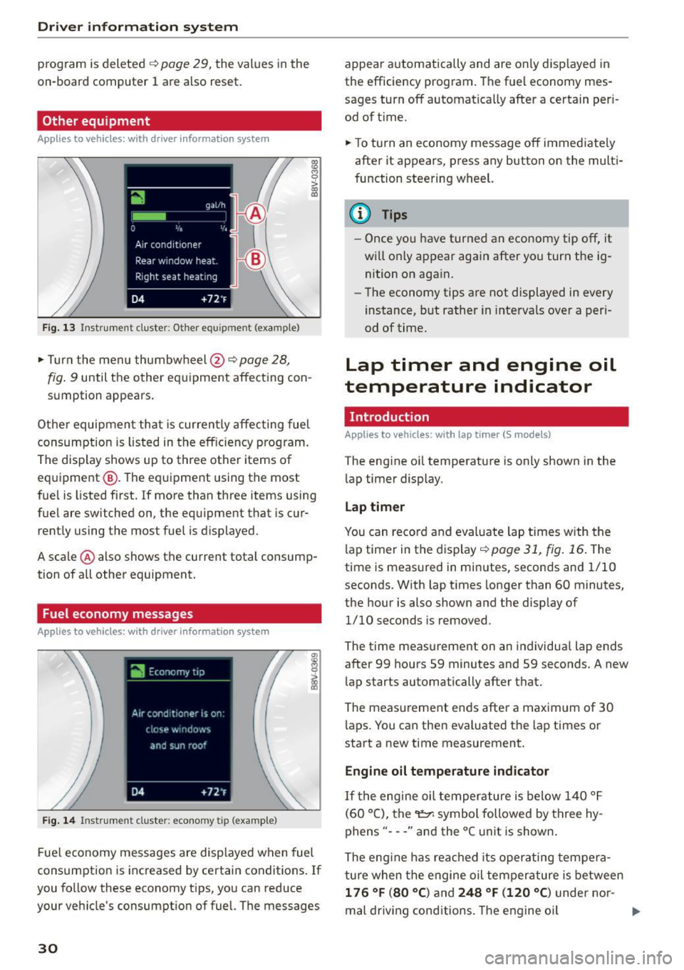
"'T urn the menu thumbwheel @ ¢ page 28,
l8 M 0
>
"' a,
fig. 9 until the other equipment affecting con
sumption appears.
Other equipment that is currently affecting fuel
consumption is listed in the efficiency prog ram.
The display shows up to three other items of
equipment @. The equipment using the most
fue l is listed first. If more than three items using
fuel are switched on, the equ ipment that is cur
rently using the most fuel is displayed.
A scale @ also shows the current total consump
tion of all other equipment.
Fuel economy messages
Applies to vehicles: with driver information system
Fig. 14 Instrument cluster: economy tip (example)
Fuel economy messages are disp layed when fuel
consumption is increased by certain conditions . If
you follow these economy tips, you can reduce
your veh icle's consumption of fuel. The messages
30
appear automatically and are only disp layed in
the efficiency program. The fuel economy mes
sages turn off automatically after a certain per i
od of t ime.
"'T o turn an economy message off immediate ly
after it appears, press any button on the multi
function steering wheel.
(D Tips
- Once you have turned an economy tip off, it
wi ll only appear again after you turn the ig
nition on again.
- The economy tips are not displayed in every
instance, but rather in intervals over a peri
od of time.
Lap timer and engine oil
temperature indicator
Introduction
Applies to veh icles: with lap tim er (S models)
The engine oil temperature is only shown in the
lap timer display.
Lap timer
You can record and evaluate lap times with the
l ap timer in the display¢
poge 31, fig. 16. The
time is measured in minutes, seconds and 1/10
seconds. With lap times longer than 60 minutes,
the hour is also shown and the display of
1/10 seconds is removed.
The time measurement on an individua l lap ends
after 99 hours 59 minutes and 59 seconds. A new
lap starts automatically after that.
The meas urement ends after a maximum of 30
laps. You can then eva luated the lap times or
start a new time measurement.
Engine oil temperature indicator
If the engine oil temperature is below 140 °F
(60 °C), the~ symbol followed by three hy
phens" ---" and the °C unit is shown .
The engine has reached its operating tempera
ture when the engine oil tempera ture is between
176 °F (80 °() and 248 °F (120 °C) under nor-
mal driving conditions. The engine oil
IJI>
Page 33 of 282

....,
N
0 > co
rl I.O
"'
"'
"'
rl
temperature may be higher if there is heavy en
gin e load and high temperatures outside. This is
not a cause for concern as long as the.
¢page 19 orllll ¢page23 indicator lights in the
display do not blink.
A WARNING
Your focus should always be on driving your
vehicle safely . As the dr iver, you have com
plete responsibility for safety in traffic . Only
use the functions such as the lap timer in such
a way that you a lways maintain complete con
trol over your vehicle in all traffic situations .
(D Tips
You can retr ieve information from the tr ip
computer while the lap timer stopwatch is
r u nning.
Opening the lap timer and measuring time
Applies to vehicles: with lap timer (5 models)
Fig. 15 Multifunction steer ing wheel: controls
Fig. 16 Instrument cluster: lap timer
Opening th e lap timer
-
"'Press the button @ on the multifunction steer
ing wheel and turn the thumbwheel @
¢fig. 15 unt il Lap timer ¢fig. 16 appea rs.
Dr iver inform atio n sy stem
.. Press the thumbwheel @ to confirm the selec
tion.
T im ing laps
"' To sta rt timing, press the thumbwheel @ while
on the menu item
Lap 1 - pre ss OK . The time
measurement is shown in line @
r=:> fig. 16.
.. To measure the lap time, press the thumb
wheel @ again while on the men u item
New
lap -pre ss O K. This also starts timing the next
round. The last time measurement moves up to
the top line
(D . Line ® contains the current lap
time .
If the symbol
ri) is green during the current lap
t ime measurement, the current time is faster
than the previous best time. If the symbol. is
red, the current time is slower @.
Displaying split time and pausing tim ing
.. To display a split time
[~l turn the thumb-
wheel @until
Split time appears in line @.
Press the thumbwheel @ to confirm the selec
tion. The split time appears for approximately 10 seconds in line @. The timing of the current
lap conti nues.
If you would like to insert a pause
m immediate
ly after the split t ime, first press the thumb
wheel @and then the menu item
Pr ess OK to go
back to confirm .
"' To insert a pause, turn the thumbwheel @ until
Pau se appears in the line @. Press the thumb
wheel @ to confirm the se lec tion . Th e pause
symbo l
m appears in line @ .
.. To continue timing, press the thumbwhee l@ .
If timing is paused , you can continue it la ter even
i f you sw itch the ignition off.
Mean ing of the indicators in the center d isp lay
¢ fig . 16:
CD Disp lay of last time measurement
@ Symbols:
-
[O]: Begin ning of time measuremen t
- . : Slowest time
- . : Fastest time
- [~]: Split time
-m : Pause
31
Page 34 of 282
Driver information system
® Current time measurement
@ Menu:
- Lap 1 (start)
- New lap (start another lap)
- Split time (time with in section of the
route)
- Pause (interrupts measurement)
- Statistics (evaluation of lap times)
- Rese t (all values are deleted)
Evaluating or resetting recorded times
Applies to vehicles: with lap timer (S models)
You can evaluate the fastest, slowest and aver
age lap times.
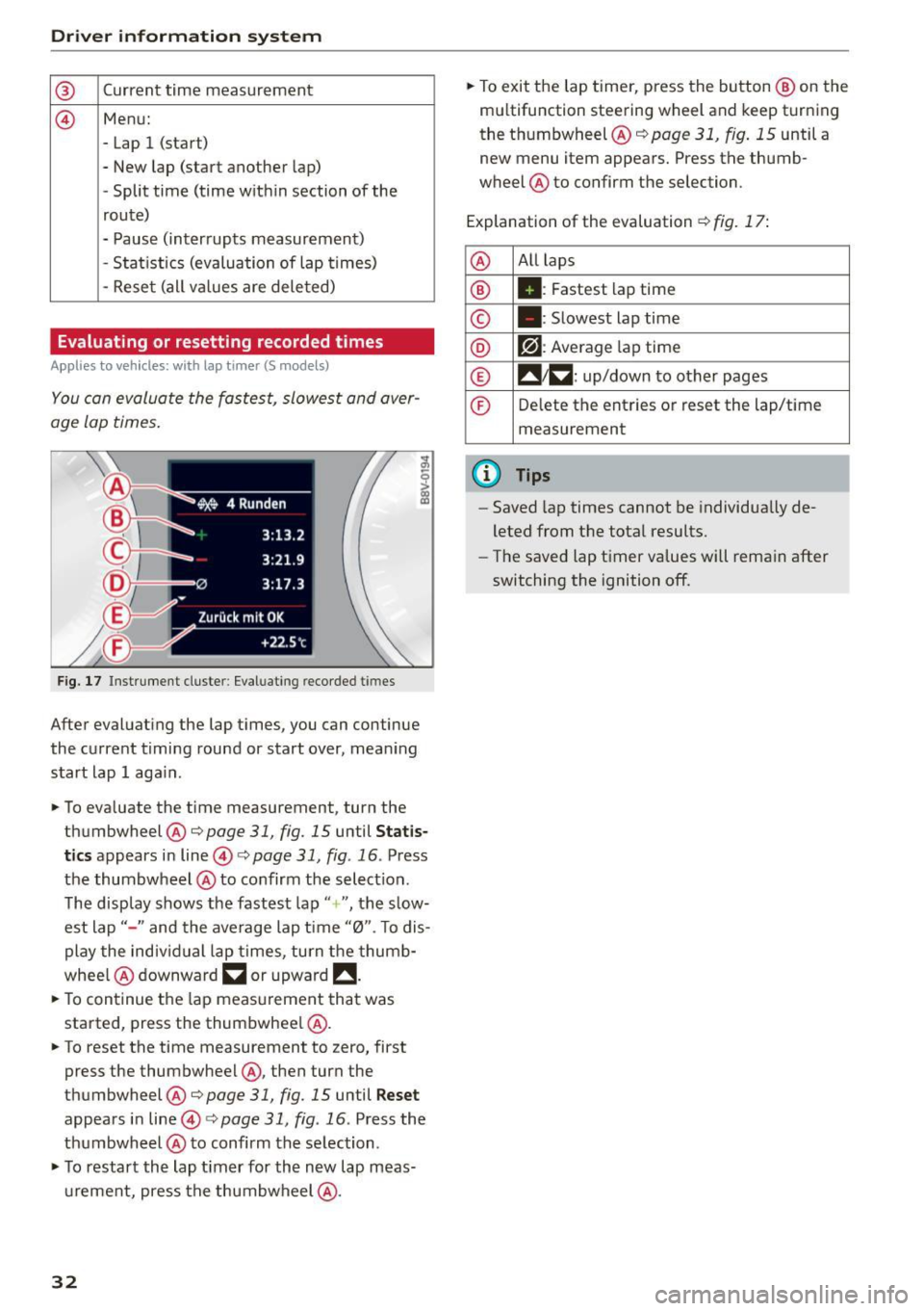
Fig. 17 Instrument cluste r: Eval uat ing reco rded t imes
After evaluating the lap times, you can continue
the current timing round or start over, meaning
start lap 1 aga in.
• To eva luate the time measurement, turn the
thumbwheel @c::>
page 31, fig. 15 until Statis
tics
appears in line@c::> page 31, fig . 16 . Press
the thumbwheel @to confirm the select ion.
The disp lay shows the fastest lap"+ ", the s low
est lap" -" and the average lap time "0". T o dis
play the individual lap times, turn the thumb
whee l@ downward
~ or upward !!.
• To continue the lap measurement that was
started, press the thumbwheel @.
• To reset the time measurement to zero, first
press the thumbwheel @, then turn the
thumbwheel @c::>page
31, fig. 15 until Reset
appears in line@i=>page31 , fig .16 . Press the
thumbwheel @to confirm the se lection .
• To restart the lap timer for the new lap meas
urement, press the thumbwheel @.
32
• To exit the lap timer, press the button @ on the
mu ltifunction steering wheel and keep turning
the thumbwheel @c::>
page 31, fig. 15 until a
new menu item appears. Press the thumb
wheel @to confirm the selection.
Explanation of the evaluation c::>
fig. 17:
@ All
laps
® II: Fastest lap time
© . : Slowest lap time
® r?l : Average lap time
® !! 1~ : up/down to other pages
© Delete the entries or reset the lap/time
measurement
@ Tips
- Saved lap times cannot be individua lly de
leted from the total results.
- The saved lap timer values will remain after
switching the ignition off.
Page 51 of 282
....,
N
0 > co
rl I.O
"'
"'
"'
rl
Sun visors
C1o... ___ J
Fig. 39 Left side: su n viso r
The sun visors can be moved out of their brackets
and turned toward the doors@. The sun shade
can also be moved back and forth lengthwise in
this posit ion.
The mirror light switches on when the cover over
the vanity mirror* @opens .
Windshield wipers
Switching windshield wipers on
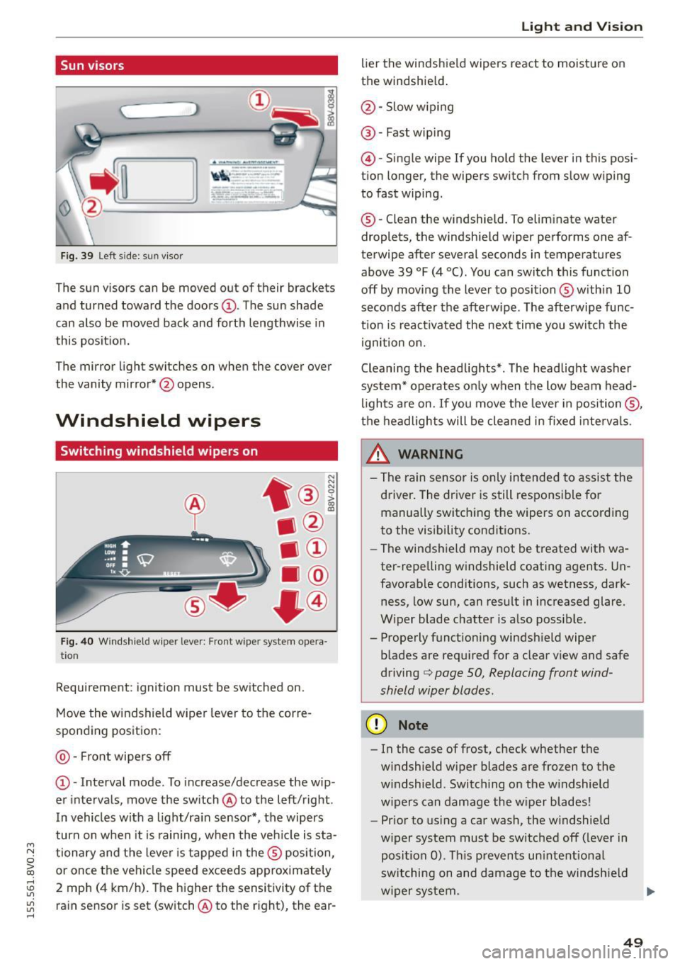
Fig. 40 Windshield wiper leve r: Front wiper system opera
tion
Requirement : ignition must be switched on.
Move the windshield wiper lever to the corre
sponding position:
@ -Front wipers off
@ -Interval mode. To increase/decrease the w ip
er intervals, move the switch @to the left/right .
I n vehicles with a light/ra in sensor*, the wipers
turn on when it is ra ining, when the veh icle is sta
tionary and the lever is tapped in the ® position,
or once the vehicle speed exceeds approximately
2 mph (4 km/h). The higher the sensitivity of the ra in sensor is set (switch @to the r ight), the ear-
Light and Visio n
lier the windshield wipers react to moisture on
the windshield .
@-Slow w iping
@ -Fast wip ing
@ -Single wipe If you ho ld the lever in this posi
tion longer, the wipers switch from slow wiping
to fast wiping.
® -C lean the w indshield. To elim inate water
droplets, the windsh ield wiper performs one af
terwipe after several seconds in temperatures
above 39 °F (4 °(). You can switch this function
off by moving the lever to position ® with in 10
seconds after the afterwipe. The afterwipe func
t ion is react ivated the nex t time you switch the
ignition on.
Cleaning the headlights*. The headlight washer
system* operates only when the low beam head
li ghts are on . If you move the lever in position @,
t h e headlights will be cleaned in fixed interva ls .
_& WARNING
- The rain sensor is only intended to assist the
driver. The driver is still responsible for manually switch ing the w ipers on according
to the visibility cond itions.
- The windshield may not be treated with wa
ter-repelling w indshield coat ing agents. Un
favorable conditions, such as wetness, dark
ness, low sun, can result in increased glare.
W iper blade chatter is also possib le.
- Properly function ing windsh ield wiper
b lades are req uired for a clear v iew and safe
driving
c::> page 50, Replacing front wind
shield wiper blades .
(D Note
- In the case of frost, check whether the
windshield wiper blades are fr ozen to the
w indshield. Switching on the w indshield
w ipers can damage the w iper blades!
- Prior to using a car wash, the windshield
w iper system must be sw itched off (leve r in
posit ion 0). T his prevents un intent ional
switching on and damage to the windsh ield
w iper system. .,.
49
Page 53 of 282
....,
N
0 > co
rl I.O
"'
"'
"'
rl
-You should not drive your vehicle or press
the windshie ld wiper lever when the wiper
arms are folded away from the w indshield.
The windshield wipers would move back in
to their original position and could damage
the hood and windshield .
- To prevent damage to the windshield wash
er system, a lways loosen wiper blades that
have frozen to the windsh ield before turn
i ng the wipers on .
- To prevent damage to the wiper blades, do
not apply gasoline, petro leum, th inning
agents or other solvents on the wiper b lades or near them.
- To prevent damage to the wiper arms or
othe r components, do not try to move the
windsh ield wipers by hand.
@ Tips
- Commerc ial hot wax such as the types used
by car washe s make it more difficult t o clean
the w indshie ld.
- You can also use the service pos ition, for ex
ample, if you want to p rotect the w indshie ld
from i cing by us ing a cover.
- You cannot activate the service pos it ion
whe n the hood is open.
Digital compass
Switching the compass on and off
Ap plies to vehicles: w ith digi tal compass
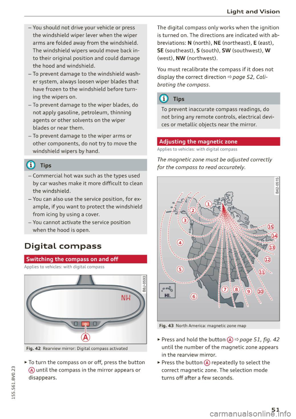
Fig. 4 2 Rearview mirro r: Dig ital compass act ivated
... To turn the compass on or off, press the button
@ until the compass in the mirror appears or
disappears.
Light and Visio n
The dig ita l compass on ly works when the ignit ion
is turned on . The directions a re indicated with ab
breviations:
N (nort h), NE (northeast), E (east),
SE (southeast), S (south), SW (southwest), W
(west), NW (northwest).
You must recalibrate t he compass if it does not
display the correct direct ion
¢ page 52, Cali
brating the compass.
(D Tips
To prevent inaccurate compass readings, do not br ing any remote controls, electrical devi
ces or metallic objects near the mirror.
Adjusting the magnetic zone
Appl ies to vehicles: wit h digita l co mp ass
The magnetic zone must be adjusted correctly
for the compass to read accurately.
®
Fig. 4 3 Nor th Ameri ca: magnet ic zone map
... Press and hold the button @ ¢page 51, fig . 42
until the number of the mag netic zone appears
in the rearview mirror .
... Press the butt on @ repeatedly to select the
correct magnetic zone. The se lection mode
tur ns off after a few seconds .
51