Page 273 of 302

....,
N
" > co
rl I.O
"' rl
"' rl
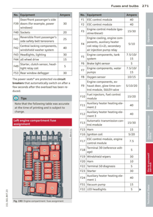
No. Equipment Ampere
Door/front passenger's side
F39 doors (for examp le, power
30
windows)
F40 Sockets 20
F41 Reversible front
passenger's
25
side safety belt tensioners
F42 Central locking components,
40
windshield washer system
F43 Headlights, light ing 30
F44 all wheel drive
15
F49 Starte
r, clutch sensor, head-
5
light re lay coil
FS3 Rear window defogger 30
The power seats* are protected v ia
ci rc uit
b reaker s
that automatically sw itch on after a
few seconds after the overload has been re
duced.
(D Tips
Note that the following table was accurate
at the time of print ing and is subject to
change.
Left engine compartment fuse
assignment
F ig. 193 Engine compartme nt: fuse assignment
No.
Fl
F2
F3
F4
F5
F6
F7
F8
F9
FlO
F ll
F12
Fl3
FlS
F l 6
F l 7
Fl8
F19
F20
F22
F23
F24
F3 1
F32
Fu se s and bulb s 2 71
Equipment Ampere
E5C contro l modu le 40
ESC contro l modu le 40
Engine control module (gas-
15/30
oli ne/d iesel)
Engine cooling, eng ine com-
ponents, auxiliary heater 5/10
coi l relay (1+2), secondary
air injection pump relay
Engine components, tank 7.5/10/
system 15
Brake light sensor 5
Engine components, wa ter 7.5/10/
pumps 15
Oxygen sensor
10/15
Engine compone nts, ex-
haust door, glow time con- 5/10/20
tro l module, SU LEV valve
Fuel injectors, fuel control
15/20
module
Auxiliary heater heating ele- 40
ment 2
Auxilia ry heater heat ing ele-
40
ment 3
Automat ic transmiss ion con-
15/30
t ro l module
Horn 15
Ignit ion coil 5/20
ESC contro l module, engine
7.5
control module
T ermina l 30 (reference volt-
5
age)
Windsh ie ld wipers
30
Horn 10
Termina l 50 diagnosis
5
Starter 30
Auxilia ry heater heat ing ele-
40
ment 1
Vacuum pump 15
L E D head lights 5
Page 274 of 302

272 Fuses and bulb s
Note that the following table was accurate
at the time of print ing and is subject to
change.
Bulbs
Replacing light bulbs
For your safety, we recommend that you have
your authorized Audi dealer replace burned out bulbs for you.
It is becoming increas ingly more and more
d iff icu lt to replace vehicle light bulbs s ince in
many cases, other parts of the car must first
be removed before you are able to get to the
bu lb . Thi s appl ies especia lly to the light bu lbs
in the front of your car which you can on ly
reach through the engine compartment .
Sheet metal and bulb ho lders can have sha rp
edges that can cause ser ious cuts, and parts
must be co rrectly taken apart and then prop
erly put back together to help prevent break
age of parts and long term damage from wa
ter that can enter housings that have not been
properly resealed.
For your safety, we recommend that you have
your authorized Audi dealer replace any bulbs
for you, since your dealer has the proper tools, the correct bulbs and the expertise.
Gas discharge lamps (Xenon lights):
Due to the high electrical vo ltage, have the
bu lbs rep laced by a qualified technician.
Headlights with Xenon light can be identified
by the high voltage sticker.
LE D headlights* require no ma intenance .
Please contact your authorized Aud i dealer if a
bu lb needs to be replaced.
A WARNING
Contact with high-voltage components of
the electrical system and improper re
placement of gas discharge (Xenon) head
light bulbs can cause serious personal in
jury and death . -
Xenon bulbs are pressurized and can ex
plode when being changed.
- Changing Xenon lamps requires the spe
cial training, instructions and equip
ment.
- Only an authorized Audi dealer or other
qualified workshop should change the
bulbs in gas discharge lamps.
A WARNING
--
There are parts with sharp edges on the
openings and on the bulb holders that can
cause ser ious cuts .
- If you are uncertain about what to do,
have the work performed by an author
ized Audi dealer or other qualified work
shop. Serious personal injury may result
from improperly performed work.
(D Tips
- If you st ill prefer to replace the light
bulbs yourself, be aware that the engine
compartment is a hazardous area to
work in
~ page 214~ &
-It is best to ask your authorized Audi
dealer whenever you need to change a
bulb.
Page 275 of 302

M N
" > co ,...., \!) ..,.,
,...., ..,., ,....,
Emergency situations
General
This chapter is intended for trained emer
gency crews and working personnel who have the necessary tools and equipment to
perform these operations.
Starting by pushing or
towing
(D Note
Vehicles with an automatic transmission
cannot be started by pushing or towing.
Starting with jumper
cables
If necessary, the engine can be started by
connecting it to the battery of another vehi
cle.
If the engine should fail to start because of a
discharged or weak battery, the battery can be
connected to the battery of
another vehicle,
using a
pair of jumper cables to start the en
gine.
Jumper cables
Use only jumper cables of sufficiently large
cross section to carry the starter current safe
ly. Refer to the manufacturer's specifications.
Use only jumper cables with
insulated termi
nal clamps which are distinctly marked :
plus(+) cable in most cases colored red
minus(-) cable
in most cases colored black.
A WARNING
Batteries contain electricity, acid, and gas.
Any of these can cause very serious or fatal
injury. Follow the instructions below for
safe handling of your vehicle's battery.
- Always shield your eyes and avoid lean
ing over the battery whenever possible.
- A discharged battery can freeze at tem
peratures just below 32 °F (0 °C). Before
Emergency situations 273
connecting a jumper cable, you must
thaw the frozen battery completely, oth
erwise it could explode.
- Do not allow battery acid to contact eyes
or skin. Flush any contacted area with
water immediately .
- Improper use of a booster battery to start a vehicle may cause an explosion.
- Vehicle batteries generate explosive gas
es. Keep sparks, flame and lighted ciga
rettes away from batteries.
- Do not try to jump start any vehicle with a low acid level in the battery.
- The voltage of the booster battery must
also have a 12-volt rating. The capacity
(Ah) of the booster battery should not be
lower than that of the discharged bat
tery . Use of batteries of different voltage
or substantially different "Ah" rating
may cause an explosion and personal in
JU ry.
- Never charge a frozen battery. Gas trap
ped in the ice may cause an explosion.
-Never charge or use a battery that has
been frozen. The battery case may have
be weakened.
- Use of batteries of different voltage or
substantially different capacity (Ah) rat
ing may cause an explosion and injury.
The capacity (Ah) of the booster battery
should not be lower than that of the dis
charged battery.
- Before you check anything in the engine
compartment, always read and heed all
WARNINGS ¢
page 214.
(D Note
-Applying a higher voltage booster bat
tery will cause expensive damage to sen
sitive electronic components, such as
control units, relays, radio, etc.
- There must be no electrical contact be
tween the vehicles as otherwise current
could already start to flow as soon as the
positive(+) terminals are connected. ..,. •
•
•
Page 276 of 302

2 7 4 Emergency situations
@ Tips
The discharged battery must be properly
connected to the vehicle's electrical sys
tem. When jump starting or charging the
battery, never connect the negative
ground cable to the battery negative post
because the batte ry manager system must
be able to detect the battery 's state of
charge. Always connect the negative
ground cab le to the negative ground post
of the battery manager control unit.
Using jump start cables
Connect the jump start cables in the exact or
der described below.
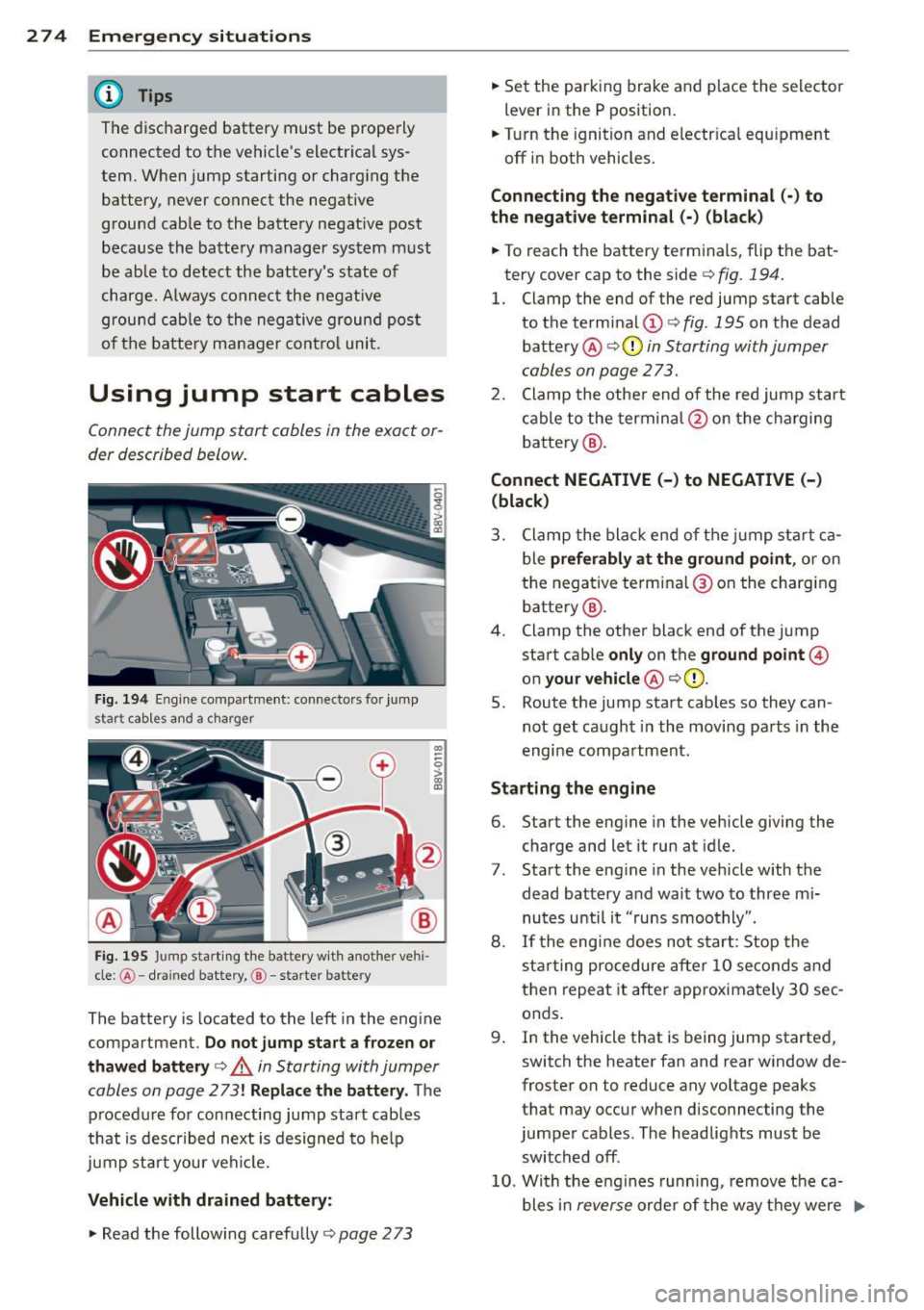
Fig. 194 Engine compartment: connecto rs fo r jump
start cab les and a charger
Fig. 195 Jump sta rting the battery with another ve hi
cle :@ -drained battery, @-starte r battery
CD
--0 > ~
The battery is located to the left in the engine
compartment.
Do not jump start a frozen or
thawed battery¢
,A in Starting with Jumper
cables on page
273! Replace the battery. The
procedure for connecting jump start cables
that is described next is designed to help
jump start your vehicle.
Vehicle with drained battery:
.. Read the following carefully ¢ page 2 73
.. Set the parking brake and place the selector
lever in the P position.
.. Turn the ignition and electr ical equipment
off in both vehicles.
Connecting the negative terminal(·) to
the negative terminal (-) (black)
.. To reach the battery terminals, flip the bat
tery cover cap to the side¢
fig. 194.
l. Clamp the end of the red jump start cable
to the terminal (!)¢
fig. 195 on the dead
battery @¢0
in Starting with Jumper
cables on page 273.
2. Clamp the other end of the red jump start
cable to the terminal @on the charging
battery @.
Connect NEGATIVE (-) to NEGATIVE (-)
(black)
3. Clamp the black end of the jump start ca
ble
preferably at the ground point, or on
the negative terminal@on the charging
battery @.
4. Clamp the other black end of the jump
start cab le
only on the ground point@
on your vehicle @¢(D.
5. Route the jump start cables so they can
not get caught in the moving parts in the
engine compartment .
Starting the engine
6. Start the engine in the vehicle giving the
charge and let it run at idle.
7 . Start the engine in the vehicle with the
dead battery and wait two to three mi nutes until it "runs smoothly" .
8.
If the engine does not start: Stop the
starting procedure after
10 seconds and
then repeat it after approximately
30 sec
onds .
9 . In the vehicle that is being jump started,
switch the heater fan and rear window de
froster on to reduce any voltage peaks
that may occur when disconnecting the
jumper cables. The headlights must be
switched off .
10. With the engines running, remove the ca
bles in
reverse order of the way they were ..,.
Page 277 of 302

M N ,....
> co ,...., \!) 1.1'1 ,...., 1.1'1 ,....,
installed. Make sure the cables do not get
caught in moving engine components .
11. Sw itch the heater fan and rear window de-
froster off.
12. Close the battery cover.
The battery is vented to the outside so that not gases enter the passenger compartment.
Make sure that the connected positive termi
nal clamps on the jump start cable have suff i
cient contact with metal.
A WARNING
Follow the warn ings and instructions from
the jump start cable manufacturer to re duce the risk of serious injuries and vehicle
damage .
If you are uns ure abo ut anything,
call roadside assistance.
- T he jump start cables must be long
enough so that the vehicles do not
touch.
- Route the jump sta rt cab les so they can
not get ca ught in the moving parts in the
engine compartment .
- Always read and follow the warnings be
fore checking anything in the engine
compartment <=>
page 214.
(D Note
Correctly jump start cables incorre ctly can
destroy the a lternator .
- Always connect the positive term inal(+)
to the positive terminal( +) and the neg
ative termina l (-) to the negative termi
nal(-) on the body ground point, but not
the negative termina l on the battery.
- Make sure the screw plugs on the batte ry
ce lls are insta lled securely. If not, tight
en the plugs before connecting the
clamps to the negat ive termina l on the
battery.
- P lease note that the connecting process
described be low for the jump start ca
bles is intended for when your vehicle is
being jump started. If you are jump
starting another vehicle, do not connect
the negat ive cab le to the negative termi
nal(·) on the drained battery, but rathe r
Emerg en cy si tuation s 275
connect it to a large metal component
that is bolted securely to the engine
bloc k, or to the engine block itsel f. If the
battery in the vehicle being jump started
is not vented to the outside, there is a
r isk of explosion due to hydrogen gas.
- Make sure that the connected positive
terminal clamps have sufficient contact
with metal.
- Do not use the battery negat ive terminal
for jump start ing or a malfunct ion could
occur in the vehicle electrical system.
Emergency towing
with commercial tow
truck
General hints
Your Audi requires special handling for tow
ing .
The following information is to be used by
commerc ial tow truck operators who know
how to operat e th eir equipment safely.
- Never to w you r Aud i. Towing will cause
damage to the engine and tran smission.
- Nev er wra p the s afety ch ains or wi nch ca
bles a round the brake li nes.
- To p revent unnece ssary dam age , your Aud i
must be t ranspo rted with a flat bed truck.
- To load the vehicle on to the fl at bed , us e
the towing loop fo und in the vehicle tool s
and attach to the front o r rear anchorage
<=> page 2 76 and <=> page 2 76.
A WARNING
A vehicle being towed is not safe for pas
sengers. Neve r allow anyone to ride in a
vehicle be ing towed, fo r any reason.
-
•
•
•
Page 278 of 302

2 76 Emergency situations
Front towing loop
Fig. 196 Right front bumper: removing the cove r
Fig. 197 Right front bumper: towing loop installed
The threaded opening for the towing loop is
located behind a cover on the right side of the
front bumper.
• Remov e the towing loop from the vehicle
tool kit¢
page 261 .
• Press inward on the upper le~ side of the
cap to remove it from the bumper
¢fig . 196.
• Insert the towing loop in the threaded open
ing until it stops¢
fig. 197 and tighten it
with a whee l wrench.
• After using, place the towing loop back in
the vehicle tool kit.
A WARNING
If the towing loop is not installed securely,
it could loosen from the threads while
towing and cause damage to the vehicle or
injury to people.
Rear towing loop
Fig. 198 Righ t rea r towing loop: cover
Fig. 199 Right rea r towing loop: towing loop installed
The towing loop threaded opening is located
in the right of the rear bumper cover under a
cover.
• Remove the towing loop from the vehicle
tool kit¢
page 261 .
• Press inward on the upper area -arrow-and
lift it upward from the
lower area¢ fig. 198.
• Insert the towing loop in the threaded open
ing until it stops ¢
fig. 199 and tighten it
w ith a wheel wrench .
• After using, p lace the towing loop back in
the vehicle tool kit.
Depending on the model, the shape of the
cover can vary .
.&_ WARNING
If the towing loop is not installed securely,
it could loosen from the threads while
towing and cause damage to the vehicle or
injury to people .
Page 279 of 302

....,
N
r--. > co
rl I.O
"' rl
"' rl
Loading the vehicle onto a flat bed truck
Fig. 200 Veh icle on flat bed truck
Front hook up
.. Align the vehicle with the centerline of the
car carr ier ramp.
.. Attach the winch hook to the front towline
eye previously installed .
Rear hook up
.. Align the vehicle with the centerline of the
car carrier ramp.
.. Attach the winch hook to the rear towline
eye previously installed.
(D} Tips
Check carefully to make sure the hook-up
is secure before moving the car up the flat
bed truck ramp.
Lifting vehicle
Lifting with workshop hoist and with
floor jack
The vehicle may only be lifted at the lifting
points illustrated .
Fig. 201 Front l ifting point
Emergency situations 2 77
Fig. 202 Rea r liftin g po int
.,. Read and heed WARNING c::> .&, .
.,. Locate lifting points c::> fig. 201 and
¢ fig. 202 .
.,. Adju st lifting arms of workshop hoist or
floor jack to match veh icle lifting points.
.. Insert a rubber pad between the floor jack/
workshop hoist and the lift ing points.
If you must lift your vehicle with a floor jack
to work underneath, be sure the vehicle is
safely supported on stands intended for this
purpose .
Front lifting point
T he lifti ng point is loca ted on the floo r pan re
info rcemen t about at the same level as the
jack mounting point
c::>fig. 201. Do not lift
the vehicle at the vertical sill reinforcement.
Rear lifting point
The lifting point is located o n the vert ica l rein
forcement of the lower sill for the on-board
jack
c::> fig. 202 .
Lifting with vehicle jack
Refer to c:;, page 266.
A WARNING
-To reduce the risk of ser ious injury and
vehicle damage .
- Always lift the vehicle only at the spe
cia l workshop hoist and floor jack lift
points illustrated
c:;, fig. 201 and
c:;, fig. 202.
- Failure to lift the veh icle at these
-
points could cause the vehicle to tilt or ..,.
Page 280 of 302

2 78 Emergency situations
fa ll from a lift if the re is a change in ve
h icle we ight d istribution and balance.
This might happen, for example, when h eavy components such as the engine
b lock or transmiss io n are removed .
- When removing heavy components like
these, ancho r vehicle to ho ist or add cor
r e spond ing weig hts to ma inta in the cen
te r of g ravity . Othe rwise, the vehicle
m ight tilt o r slip off th e hois t, c aus ing
s er ious pers on al injury.
(D Note
-Be awa re of th e f ollowing poin ts b efo re
li fting th e vehicle:
- The vehicle should never be lifted or
jacked up from underneath the engine oil pan, the transmission housing, the
front or rear axle or the body side members. This could lead to serious
damage .
- To avoid damage to the underbody or
chassis frame, a rubber pad must be
inserted between the floor jack and
the lift points.
- Before driving over a workshop hoist,
check that the vehicle weight does not
exceed the permissible lifting capacity
of the hoist .
- Before driving over a workshop hoist,
ensure that there is sufficient clear
ance between the hoist and low parts
of the vehicle.