Page 146 of 180
8-36
8
9
10
11
12
13
14
3. Release the parking brake lever.
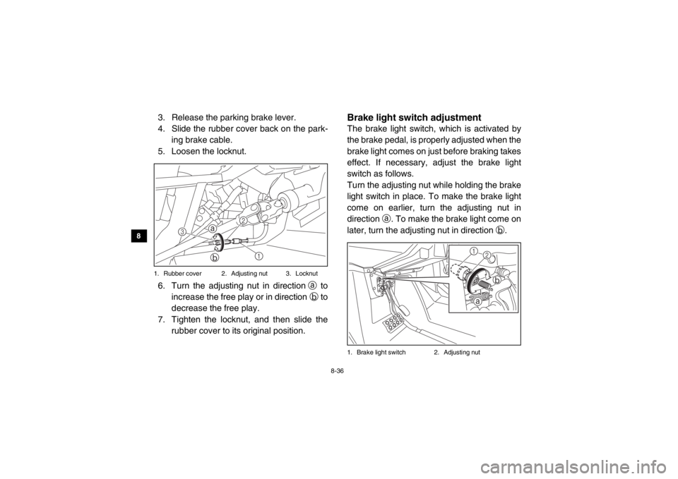
4. Slide the rubber cover back on the park- ing brake cable.
5. Loosen the locknut.1. Rubber cover 2. Adjusting nut 3. Locknut6. Turn the adjusting nut in direction a to
increase the free play or in direction b to
decrease the free play.
7. Tighten the locknut, and then slide the rubber cover to its original position.
EVU00880Brake light switch adjustmentThe brake light switch, which is activated by
the brake pedal, is properly adjusted when the
brake light comes on just before braking takes
effect. If necessary, adjust the brake light
switch as follows.
Turn the adjusting nut while holding the brake
light switch in place. To make the brake light
come on earlier, turn the adjusting nut in
direction a. To make the brake light come on
later, turn the adjusting nut in direction b.1. Brake light switch 2. Adjusting nut
1
ab
2
3
1a
b
2
1XP7B_EE.book Page 36 Tuesday, February 4, 2014 3:40 PM
Page 147 of 180
8-37
1
2
3
4
5
6
78
9
10
11
12
13
14
EVU00890Cable inspection and lubrication
WARNING
Damaged cables could restrict operation,
which may cause an accident or injury. In-
spect control cables frequently and re-
place damaged cables. Corrosion can
result when the outer covering of control
cables becomes damaged. Cables can
also become frayed or kinked.Lubricate the cable ends. If the cables do not
operate smoothly, ask a Yamaha dealer to re-
place them.
EVU00900Brake pedal and accelerator pedal
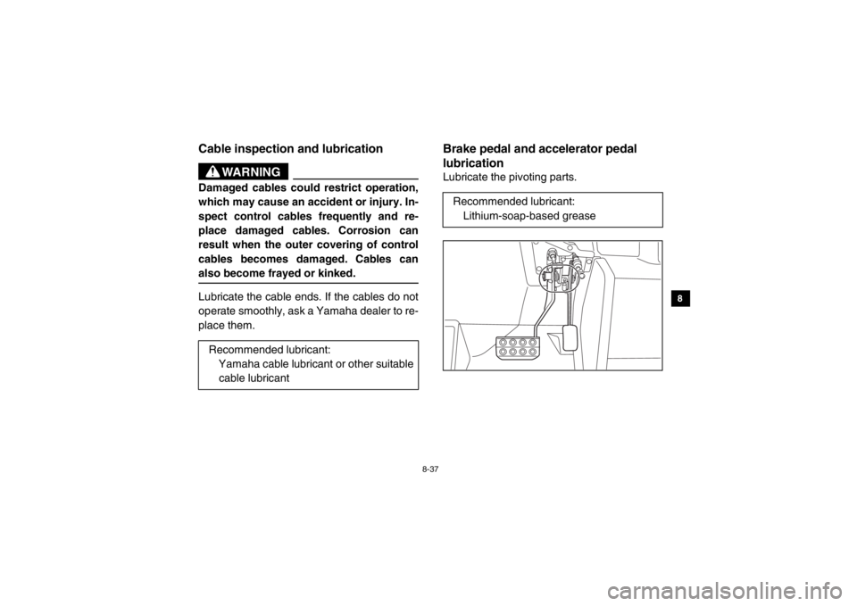
lubricationLubricate the pivoting parts.
Recommended lubricant: Yamaha cable lubricant or other suitable
cable lubricantRecommended lubricant: Lithium-soap-based grease
1XP7B_EE.book Page 37 Tuesday, February 4, 2014 3:40 PM
Page 163 of 180
8-53
1
2
3
4
5
6
78
9
10
11
12
13
14
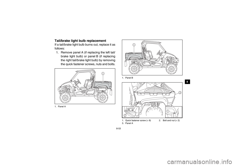
EVU01000Tail/brake light bulb replacementIf a tail/brake light bulb burns out, replace it as
follows:1. Remove panel A (if replacing the left tail/ brake light bulb) or panel B (if replacing
the right tail/brake light bulb) by removing
the quick fastener screws, nuts and bolts.1. Panel A 1. Panel B
1. Quick fastener screw (
× 8) 2. Bolt and nut ( × 2)
3. Panel A
1
1
1
3
2 1
1XP7B_EE.book Page 53 Tuesday, February 4, 2014 3:40 PM
Page 164 of 180
8-54
8
9
10
11
12
13
14
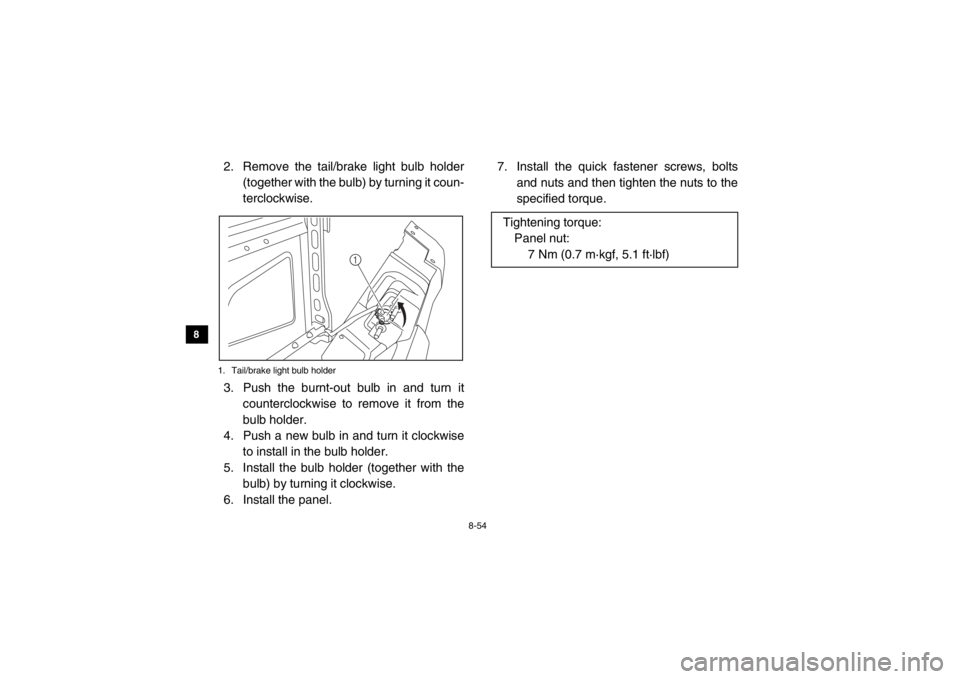
2. Remove the tail/brake light bulb holder (together with the bulb) by turning it coun-
terclockwise.1. Tail/brake light bulb holder3. Push the burnt-out bulb in and turn itcounterclockwise to remove it from the
bulb holder.
4. Push a new bulb in and turn it clockwise to install in the bulb holder.
5. Install the bulb holder (together with the bulb) by turning it clockwise.
6. Install the panel. 7. Install the quick fastener screws, bolts
and nuts and then tighten the nuts to the
specified torque.
1
Tightening torque:Panel nut: 7 Nm (0.7 m·kgf, 5.1 ft·lbf)
1XP7B_EE.book Page 54 Tuesday, February 4, 2014 3:40 PM
Page 168 of 180

9-1
9
10
11
12
13
14
EVU01030
1-CLEANING AND STORAGE
CleaningFrequent, thorough cleaning of your vehicle
will not only enhance its appearance but will
improve its general performance and extend
the useful life of many components. 1. Before cleaning the vehicle:
a. Block off the end of the exhaust pipeto prevent water entry. A plastic bag
and strong rubber band may be used.
b. Make sure the spark plug and all filler caps are properly installed.
2. If the engine case is excessively greasy,
apply degreaser with a paint brush. Do
not apply degreaser to the wheel axles. 3. Rinse the dirt and degreaser off with a
garden hose. Use only enough pressure
to do the job. WARNING! Test the
brakes after washing. Apply the
brakes several times at slow speeds
to let friction dry out the linings. Wet
brakes may have reduced stopping
ability, increasing the chance of an ac-
cident. NOTICE: Excessive water
pressure may cause water seepage
and deterioration of wheel bearings,
brakes, transmission seals and elec-
trical devices. Many expensive repair
bills have resulted from improper
high-pressure detergent applications,
such as those available in coin-oper-
ated car washers.1XP7B_EE.book Page 1 Tuesday, February 4, 2014 3:40 PM
Page 174 of 180
10-4
10
11
12
13
14
Vehicle load: 300 kg – maximum (661 lb – maximum):
Front:70.0 kPa (0.700 kgf/cm
2, 10 psi)
Rear:
120.0 kPa (1.200 kgf/cm2, 17 psi)
Front wheel:Wheel type:Cast wheel
Rim size:
12 × 6.0ATRear wheel:Wheel type:
Cast wheel
Rim size:
12 × 7.5ATFront brake:Type:
Disc brake
Operation:
Unified brake
Recommended fluid: DOT 4Rear brake:Type:
Disc brake
Operation: Unified brake
Recommended fluid: DOT 4
Front suspension:Type:Double wishbone
Spring/shock absorber type:
Coil spring/gas-oil damper
Wheel travel: 205 mm (8.1 in)Rear suspension:Type:
Double wishbone
Spring/shock absorber type: Coil spring/gas-oil damper
Wheel travel: 205 mm (8.1 in)Electrical system:Ignition system:TCI
Charging system: AC magnetoBattery:Model:U1-H11L
Voltage, capacity: 12 V, 28.0 AhHeadlight:Bulb type:Halogen bulbBulb voltage, wattage
× quantity:
Headlight:
12 V, 35.0/35.0 W × 2
Tail/brake light: 12 V, 5.0/21.0 W × 2
1XP7B_EE.book Page 4 Tuesday, February 4, 2014 3:40 PM
Page 175 of 180

10-5
1
2
3
4
5
6
7
8
910
11
12
13
14
Neutral indicator light:LED
Reverse indicator light: LED
Coolant temperature warning light:
LED
Engine trouble warning light: LED
Parking brake indicator light: LED
On-Command four-wheel-drive/differential gear lock indica-
tor: LCD
High-range indicator light:
LED
Low-range indicator light: LED
Differential gear lock indicator light: LED
EPS warning light:
LED
Helmet/Seat belt indicator light: 14 V, 0.85 W × 2Fuses:Main fuse:
40.0 A
Fuel injection system fuse: 10.0 A
EPS fuse: 40.0 A
Headlight fuse:
15.0 A Signaling system fuse:
10.0 A
Ignition fuse: 10.0 A
Auxiliary DC jack fuse:
10.0 A
Backup fuse: 10.0 A
Four-wheel-drive motor fuse: 10.0 A
Radiator fan fuse:
25.0 A
For Europe only
The figures quoted are emission levels and
are not necessarily safe working levels. Whilst
there is a correlation between the emission
and exposure levels, this cannot be used reli-
ably to determine whether or not further pre-
cautions are required.
Factors that influence the actual level of expo-
sure of work-force include the characteristics
of the work room, the other sources of noise,
etc. i.e. the number of machines and other ad-
jacent processes, and the length of time for
which an operator is exposed to the noise.
Also the permissible exposure level can vary
1XP7B_EE.book Page 5 Tuesday, February 4, 2014 3:40 PM