Page 164 of 232
158IN CASE OF AN EMERGENCY
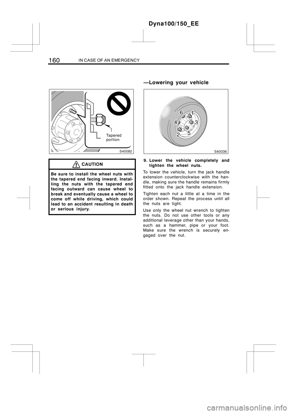
Left−side wheel
Right−hand thread Left−hand threadRight−side wheel
7. Remove the stop bolts, change tires,
reinstall the stop bolts and tighten
them.
Skip this step to the next unless the inner
rear tire is flat.
Use the small end of the wheel nut
wrench to loosen the stop bolts. Note that
both the stop bolts and the wheel nuts on
the right and left side of the vehicle have
different threads.
Lift the flat tire straight off and put it
aside.
Roll the spare wheel into position and
align the holes in the wheel with the bolts.
Then lift up the wheel and get at least the
top bolt started through its hole. Wiggle
the tire and press it back over the other
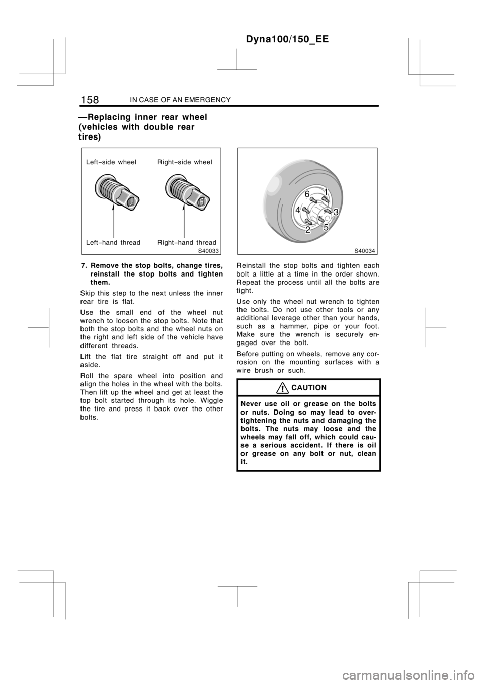
bolts.Reinstall the stop bolts and tighten each
bolt a little at a time in the order shown.
Repeat the process until all the bolts are
tight.
Use only the wheel nut wrench to tighten
the bolts. Do not use other tools or any
additional leverage other than your hands,
such as a hammer, pipe or your foot.
Make sure the wrench is securely en-
gaged over the bolt.
Before putting on wheels, remove any cor-
rosion on the mounting surfaces with a
wire brush or such.
CAUTION
Never use oil or grease on the bolts
or nuts. Doing so may lead to over-
tightening the nuts and damaging the
bolts. The nuts may loose and the
wheels may fall off, which could cau-
se a serious accident. If there is oil
or grease on any bolt or nut, clean
it.
Dyna100/150_EE
—Replacing inner rear wheel
(vehicles with double rear
tires)
Page 165 of 232
IN CASE OF AN EMERGENCY159
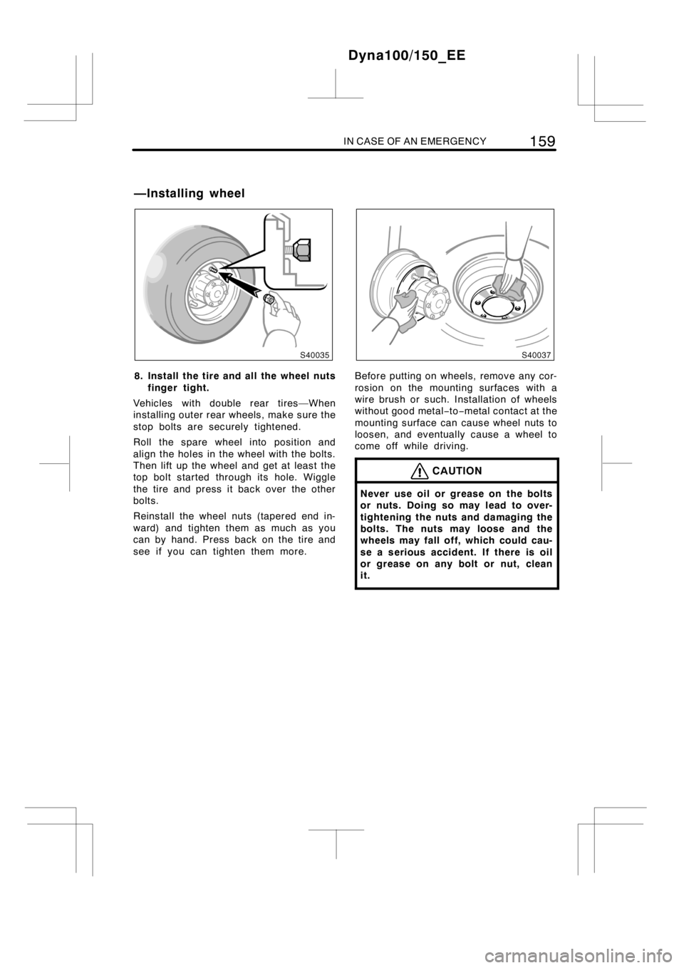
8. Install the tire and all the wheel nuts
finger tight.
Vehicles with double rear tires—When
installingouter rear wheels, make sure the
stop bolts are securely tightened.
Roll the spare wheel into position and
align the holes in the wheel with the bolts.
Then lift up the wheel and get at least the
top bolt started through its hole. Wiggle
the tire and press it back over the other
bolts.
Reinstall the wheel nuts (tapered end in-
ward) and tighten them as much as you
can by hand. Press back on the tire and
see if you can tighten them more.Before putting on wheels, remove any cor-
rosion on the mounting surfaces with a
wire brush or such. Installation of wheels
without good metal−to−metal contact at the
mounting surface can cause wheel nuts to
loosen, and eventually cause a wheel to
come off while driving.
CAUTION
Never use oil or grease on the bolts
or nuts. Doing so may lead to over-
tightening the nuts and damaging the
bolts. The nuts may loose and the
wheels may fall off, which could cau-
se a serious accident. If there is oil
or grease on any bolt or nut, clean
it.
Dyna100/150_EE
—Installing wheel
Page 166 of 232
160IN CASE OF AN EMERGENCY
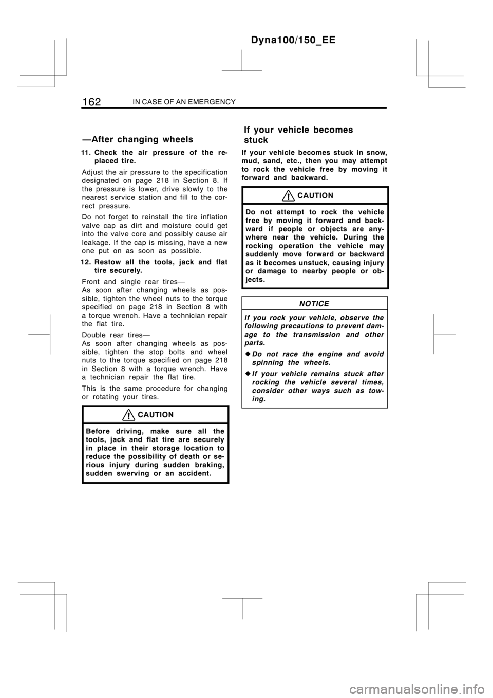
Tapered
portion
CAUTION
Be sure to install the wheel nuts with
the tapered end facing inward. Instal-
ling the nuts with the tapered end
facing outward can cause wheel to
break and eventually cause a wheel to
come off while driving, which could
lead to an accident resulting in death
or serious injury.
9. Lower the vehicle completely and
tighten the wheel nuts.
To lower the vehicle, turn the jack handle
extension counterclockwise with the han-
dle, making sure the handle remains firmly
fitted onto the jack handle extension.
Tighten each nut a little at a time in the
order shown. Repeat the process until all
the nuts are tight.
Use only the wheel nut wrench to tighten
the nuts. Do not use other tools or any
additional leverage other than your hands,
such as a hammer, pipe or your foot.
Make sure the wrench is securely en-
gaged over the nut.
Dyna100/150_EE
—Lowering your vehicle
Page 168 of 232
162IN CASE OF AN EMERGENCY
11. Check the air pressure of the re-
placed tire.
Adjust the air pressure to the specification
designated on page 218 in Section 8. If
the pressure is lower, drive slowly to the
nearest service station and fill to the cor-
rect pressure.
Do not forget to reinstall the tire inflation
valve cap as dirt and moisture could get
into the valve core and possibly cause air
leakage. If the cap is missing, have a new
one put on as soon as possible.
12. Restow all the tools, jack and flat
tire securely.
Front and single rear tires—
As soon after changing wheels as pos-
sible, tighten the wheel nuts to the torque
specified on page 218 in Section 8 with
a torque wrench. Have a technician repair
the flat tire.
Double rear tires—
As soon after changing wheels as pos-
sible, tighten the stop bolts and wheel
nuts to the torque specified on page 218
in Section 8 with a torque wrench. Have
a technician repair the flat tire.
This is the same procedure for changing
or rotating your tires.
CAUTION
Before driving, make sure all the
tools, jack and flat tire are securely
in place in their storage location to
reduce the possibility of death or se-
rious injury during sudden braking,
sudden swerving or an accident.
If your vehicle becomes stuck in snow,
mud, sand, etc., then you may attempt
to rock the vehicle free by moving it
forward and backward.
CAUTION
Do not attempt to rock the vehicle
free by moving it forward and back-
ward if people or objects are any-
where near the vehicle. During the
rocking operation the vehicle may
suddenly move forward or backward
as it becomes unstuck, causing injury
or damage to nearby people or ob-
jects.
NOTICE
If you rock your vehicle, observe the
following precautions to prevent dam-
age to the transmission and other
parts.
zDo not race the engine and avoid
spinning the wheels.
zIf your vehicle remains stuck after
rocking the vehicle several times,
consider other ways such as tow-
ing.
Dyna100/150_EE
—After changing wheelsIf your vehicle becomes
stuck
Page 171 of 232

IN CASE OF AN EMERGENCY165
If towing is necessary, we recommend
you to have it done by any authorized
Toyota dealer or repairer, or qualified
professional, such as a commercial tow
truck service.
If towing service is not available in an
emergency, your vehicle may be tempo-
rarily towed by a cable or chain se-
cured to one of the following parts:
Front: Front emergency towing hook
Rear: Rear emergency towing eyelet
Use extreme caution when towing the
vehicle.
NOTICE
Only use specified towing hook or
eyelet; otherwise your vehicle may be
damaged.
A driver must be in the vehicle to steer
it and operate the brakes.
Towing in this manner may be done only
on hard−surfaced roads for a short dis-
tance and at low speeds. Also, the
wheels, axles, drive train, steering and
brakes must all be in good condition.
CAUTION
Use extreme caution when towing the
vehicle. Avoid sudden starts or errat-
ic driving maneuvers which would
place excessive stress on the emer-
gency towing hook or eyelet and tow-
ing cable or chain. The hook or eye-
let and towing cable or chain may
break and cause serious injury or
damage.
NOTICE
Use only a cable or chain specifically
intended for use in towing vehicles.
Securely fasten the cable or chain to
the towing hook or eyelet provided.
Before towing, release the parking brake
and put the transmission in neutral. The
engine switch must be in “ACC” (engine
off) or “ON” (engine running) position.
CAUTION
If the engine is not running, the pow-
er assist for the brakes and steering
will not work so steering and braking
will be much harder than usual.
Dyna100/150_EE
Page 208 of 232

202DO−IT−YOURSELF MAINTENANCE: Electrical components
Low O.K.
ADDING DISTILLED WATER
1. Remove the vent plugs.
2. Add distilled water to cells needing
fluid.
If the side of your battery is covered,
check the water level by looking down
directly above the cell as illustrated
above.
3. Retighten the vent plugs securely.
NOTICE
Do not overfill the cells. Excess elec-
trolyte could squirt out of the battery
during heavy charging, causing corro-
sion or damage.
During recharging, the battery is pro-
ducing hydrogen gas.
Therefore, before recharging:
1. If recharging with the battery installed
on the vehicle, be sure to disconnect
the ground cable.
2. Be sure the power switch on the re-
charger is off when connecting the
charger cables to the battery and when
disconnecting them.
CAUTION
Always charge the battery in an un-
confined area. Do not charge the bat-
tery in a garage or closed room
where there is not sufficient ventila-
tion.
NOTICE
Never recharge the battery while the
engine is running. Also, be sure all
accessories are turned off.
Dyna100/150_EE
Battery recharging
precautions
Page 213 of 232
DO−IT−YOURSELF MAINTENANCE: Electrical components207
3. Release the bulb retaining spring
and remove the bulb. Install a new
bulb and the bulb retaining spring.
To install a bulb, align the tabs of the
bulb with the cutouts of the mounting
hole.4. Install the rubber cover with the
“TOP” mark upward, and fit it se-
curely on the boss. Plug in the con-
nector.
Make sure the rubber cover fits securely
on the bulb base and the mounting body.
Aiming is not necessary after replacing
the bulb. When aiming adjustment is nec-
essary, contact any authorized Toyota
dealer or repairer, or another duly quali-
fied and equipped professional.
Dyna100/150_EE
Page 225 of 232

SPECIFICATIONS219
Instrument panel
Left side of the vehicle
Fuses (type A)
1. CIG 15 A:Cigarette lighter
2. DOOR 30 A:Power door locksystem
3. IG1−NO.2 10 A:Gauges and meters,
service reminder indicators and warning
buzzer, back−up lights, back buzzer
4. WIP 30 A: Windshield wipers and
washer
5. A/C 10 A:Air conditioningsystem
6.IG110A:Back−up lights, back buzzer
7. TRN 10 A:Turn signal lights, emergen-
cy flashers
8. ECU−IG 10 A:Anti−lock brake system9. RR−FOG 10 A:Rear fog light
10. OBD 10 A:On−board diagnosissystem
11 . D O M E 1 0 A :Interior lights
12. ECU−B10A:Headlights, tail lights
13. TAIL 15 A:Tail lights, front position
lights, license plate lights, instrument
panel lights, rear fog light
14. H−LP LL 10 A (vehicle with daytime
running light system):Left−hand
headlight (low beam)
15. H−LP RL 10 A (vehicle with daytime
running light system):Right−hand
headlight (low beam)
16. H−LP LH 10 A (vehicle with daytime
running light system) or H−LP LH 15
A (vehicle without daytime running
light system):Left−hand headlight
(high beam)
17. H−LP RH 10 A (vehicle with daytime
running light system) or H−LP RH 15
A (vehicle without daytime running
light system):Right−hand headlight
(high beam)
18. HORN 10 A:Horns
19. HAZ 10 A:Emergency flashers
20. STOP 10 A:Stop lights
21. ST 10 A:Starting system
22.IG210A:SRS airbag system
23.A/CNO.210A:Air conditioning sys-
tem
24. SPARE 10 A:Spare fuse
25. SPARE 15 A:Spare fuse
26. SPARE 20 A:Spare fuse
27. SPARE 30 A:Spare fuse
28. FOG 15A:Fog light
29. F/HTR 30 A:Front heater
30. EFI1 10 A:Engine control system
31. ALT−S10A:Charging system, charg-
ing system warning light
32.AM210A:Engine switch
Dyna100/150_EE
Fuses