Page 25 of 164

WARNING■Children must never be seated with their head in the deployment area of
the side airbag – risk of injury!■
Do not place any objects within the deployment area of the side airbags –
risk of injury!
Classification of child seats
Read and observe
and on page 19 first.
Classification of child seats according to the ECE-R 44 standard.
GroupWeight of the childApproximate age0up to 10 kgup to 9 months0+up to 13 kgup to 18 months19 - 18 kgup to 4 years215 - 25 kgup to 7 years322 - 36 kgover 7 years
Use of child seats fastened with a seat belt Read and observe
and on page 19 first.
Overview of the usability of child seats fastened with a seat belt on each ofthe seats in accordance with the ECE-R 16 standard.
GroupFront passenger seatRear seats0
up to 10 kgUU0+
up to 13 kgUU1
9 - 18 kgUU2
15 - 25 kgUU3
22 - 36 kgUU
Child seat category “Universal” - a child seat designed to be attached to
the seat using the seat belt.
UFastening systems
Introduction
This chapter contains information on the following subjects:
attachment points of the
system
22
Use of child seats with the
system
23
Attachment points of the
system
23
attachment points of the system
Fig. 15
Rear seat: ISOFIX
is a system for a fast and secure child-seat mounting.
There are two lashing eyes between the rear exterior seat backrest and the
surface of the seat itself on both sides for fixing the ISOFIXsys-
tem » Fig. 15 child seat in place.
WARNING■
Always refer to the instructions of the manufacturer of the child seat
when installing and removing a child seat with the system.■
Never attach other child seats, belts or objects to the attachment points
intended for the installation of a child seat with the
system – risk of
death!
Note
■ A child seat fitted with the system can only be mounted in a vehicle fit-
ted with an system if the child seat has been approved for this type of ve-
hicle. Further information is available from a ŠKODA Partner.■
Child seats with the
system can be purchased from ŠKODA Original Ac-
cessories.
22Safety
Page 26 of 164

Use of child seats with the systemOverview of the use-ability of the child seats fastened with the system on
each of the seats in accordance with the ECE-R 16 standard.GroupSize class of
the child seat a)Front passenger seatRear seats0
up to 10 kgEXIL-SU0+
up to 13 kgE
XIL-SU
DC
1
9 - 18 kg
D
XIL-SU IUF
CBB1A2
15 - 25 kg XIL-SU3
22 - 36 kg XIL-SUa)
The size category is shown on the label attached to the child seat.
The seat is suitable for the installation of a child seat with “Semi-
Universal” approval. The “Semi-Universal” category means that the child
seat with the
system is approved for your vehicle. Observe the list
of vehicles that comes with the child seat.
The seat is suitable for the installation of a
child seat with the
“Universal” approval and attachment with the
system belt.
The seat is not fitted with
system attachment points.IL-SUIUFXAttachment points of the systemFig. 16
Rear seat: TOP TETHER
is a fastening system, which restricts the movement of the upper part
of the child seat.
23Transporting children safely
Page 27 of 164
The attachment points for attaching the belt for a child seat with the
system are located on the back of the rear seat backrests » Fig. 16.WARNING■
Always refer to the instructions from the manufacturer of the child seat
when installing and removing a child seat with the system.■
Only use child seats with the
system on the seats with the at-
tachment points.
■
Only ever attach one belt from the child seat to a locking eye.
■
On no account should you equip your vehicle, e.g. mount screws or other
anchorage points.
24Safety
Page 28 of 164
25Transporting children safely
Page 29 of 164
Fig. 17
Cockpit
26Using the system
Page 30 of 164

Using the system
Cockpit
OverviewDoor opening lever
41
Electric windows
44
Central locking system
43
Electric exterior mirror adjustment
54
Air outlet vent
71
Operating lever:
› Turn signal lights and main beam, headlight flasher
49
›Speed regulating system
87
Parking ticket holder
60
Steering wheel:
› With horn
› With driver’s front airbag
16
Instrument cluster: Instruments and warning lights
28
Operating lever:
› Multifunction display
30
›Windscreen wiper and wash system
52
Button for rear window heater
52
START-STOP button
88
Depending on equipment fitted:
› Operating controls for the heating
71
›Operating controls for the air conditioning system
71
Socket for the cradle for the Move & Funmultifunction device
73
Warning light for the deactivated front seat passenger airbag
18
Interior rear-view mirror
54
Button for hazard warning light system
50
Front passenger airbag
16
Bag holder
64
Storage compartment on the front passenger side
64
Air outlet vent
71
Power window in the front passenger door
44
Door opening lever
411234567891011121314151617181920212223Light switch48
Bonnet release lever
107
Regulator for headlamp beam adjustment for the headlights
48
Lever for adjusting the steering wheel
10
Ignition lock
77
Pedals
80
Regulator for left seat heating
57
Radio
Button for City Safe Drive system
90
Handbrake lever
79
Depending on equipment fitted:
› Gearshift lever (manual gearbox)
79
›Selector lever (automated gearbox)
81
Storage compartment
61
Regulator for right seat heating
57
Note
■
Cars with factory-fitted radio are supplied with separate instructions for op-
erating such equipment.■
The arrangement of the controls right-hand drive models may differ from the
layout shown in » Fig. 17. The symbols on the controls and switches are the
same as for left-hand drive models.
2425262728293031323334353627Cockpit
Page 31 of 164

Instruments and control lights
Instrument cluster
Introduction
This chapter contains information on the following subjects:
Overview
28
Speedometer
28
Fuel reserve display
29
Tachometer
29
Counter for distance driven
30
Service interval display
30
Gear recommendation
30
The instrument cluster gives the driver basic information such as the current
speed, engine speed, the state of some vehicle systems and the like.
WARNINGConcentrate fully at all times on your driving! As the driver you are fully re-
sponsible for road safety.
Overview
Fig. 18
Instrument cluster - Version 1
Fig. 19
Instrument cluster - Version 2
Read and observe
on page 28 first.
Speedometer » page 28
Display:
› with fuel gauge (only in the instrument cluster - version 2)
» page 29
› With counter for distance driven
» page 30
› With service interval display
» page 30
› With multifunction display
» page 30
› with outside temperature display
» page 32
The counter for the distance travelled button (trip) » page 30
Fuel gauge » page 29
Engine revolutions counter » page 29
Adjust button for the time » page 33
Speedometer
Read and observe
on page 28 first.
The speedometer displays the current speed.
12345628Using the system
Page 32 of 164

Fuel reserve displayFig. 20
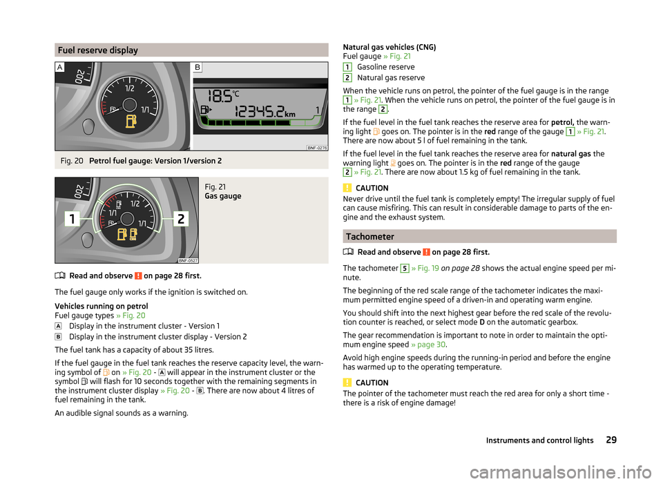
Petrol fuel gauge: Version 1/version 2
Fig. 21
Gas gauge
Read and observe on page 28 first.
The fuel gauge only works if the ignition is switched on.
Vehicles running on petrol
Fuel gauge types » Fig. 20
Display in the instrument cluster - Version 1
Display in the instrument cluster display - Version 2
The fuel tank has a capacity of about 35 litres.
If the fuel gauge in the fuel tank reaches the reserve capacity level, the warn-
ing symbol of on
» Fig. 20 -
will appear in the instrument cluster or the
symbol will flash for 10 seconds together with the remaining segments in
the instrument cluster display » Fig. 20 -
. There are now about 4 litres of
fuel remaining in the tank.
An audible signal sounds as a warning.
Natural gas vehicles (CNG)
Fuel gauge » Fig. 21
Gasoline reserve
Natural gas reserve
When the vehicle runs on petrol, the pointer of the fuel gauge is in the range1
» Fig. 21 . When the vehicle runs on petrol, the pointer of the fuel gauge is in
the range
2
.
If the fuel level in the fuel tank reaches the reserve area for petrol, the warn-
ing light
goes on. The pointer is in the red range of the gauge
1
» Fig. 21 .
There are now about 5 l of fuel remaining in the tank.
If the fuel level in the fuel tank reaches the reserve area for natural gas the
warning light goes on. The pointer is in the
red range of the gauge
2
» Fig. 21 . There are now about 1.5 kg of fuel remaining in the tank.
CAUTION
Never drive until the fuel tank is completely empty! The irregular supply of fuel
can cause misfiring. This can result in considerable damage to parts of the en-
gine and the exhaust system.
Tachometer
Read and observe
on page 28 first.
The tachometer
5
» Fig. 19 on page 28 shows the actual engine speed per mi-
nute.
The beginning of the red scale range of the tachometer indicates the maxi-
mum permitted engine speed of a driven-in and operating warm engine.
You should shift into the next highest gear before the red scale of the revolu-
tion counter is reached, or select mode D on the automatic gearbox.
The gear recommendation is important to note in order to maintain the opti-
mum engine speed » page 30.
Avoid high engine speeds during the running-in period and before the engine
has warmed up to the operating temperature.
CAUTION
The pointer of the tachometer must reach the red area for only a short time -
there is a risk of engine damage!1229Instruments and control lights