Page 137 of 164

An emergency locking mechanism is located on the face side of the doors
which have no locking cylinder, it is only visible after opening the door.›
Insert the key into the slot » Fig. 120 -
.
›
Turn the key in the right-hand door is in the horizontal position in the direc-
tion of arrow » Fig. 120 -
and turn it against the direction of the arrow for
the left door.
After closing the door, it cannot be opened from the outside. The door is un-
locked by pulling on the door opening lever and is then opened from the out-
side.
Unlocking the tailgate
Fig. 121
Emergency unlocking of the lug-
gage compartment lid
The boot lid can be unlocked manually in an emergency.
›
Insert the vehicle key into the slot
A
» Fig. 121 in the trim panel as far as it
goes .
›
Unlock the lid by moving it in the direction of the arrow.
›
Open the boot lid.
Replacing windscreen wiper blades
Introduction
This chapter contains information on the following subjects:
Replacing the windscreen wiper blades
134
Replacing the rear window wiper blade
135WARNINGReplace the windscreen wiper blades once or twice a year for safety rea-
sons. These can be purchased from a ŠKODA Partner.CAUTIONIf the windscreen wipers are handled carelessly, there is a risk of damage to
the windscreen.
Replacing the windscreen wiper blades
Fig. 122
Windscreen wiper blade
Read and observe and on page 134 first.
When in the rest position, the wiper arms cannot be fold down from the wind- screen. Before replacing the windscreen wiper blade, put the windscreen wip-
er arms into the service position.
Service position for changing wiper blades
›
Closing the bonnet.
›
Switch the ignition on and off again.
›
Then press the windscreen wiper lever into position
4
» Fig. 42 on page 53
within 10 seconds – the wiper arms move into the service position.
Removing the wiper blade
›
Raise the windscreen wiper arm from the rear window and slightly tilt the
windscreen wiper blade towards the wiper arm, arrow
1
» Fig. 122 .
›
Hold the windscreen wiper arm at the top end.
›
Press the locking button
A
and remove the wiper blade in the direction of
arrow
2
.
Attaching the wiper blade
›
Push the windscreen wiper blade until the stop and it locks in place.
›
Check that the wiper blade is correctly attached.
›
Fold the wiper arm back to the windscreen.
›
Turn on the ignition and press the windscreen wiper lever into position
4
» Fig. 42 on page 53 ; the windscreen wiper arms move to the home posi-
tion.
134Do-it-yourself
Page 138 of 164

Replacing the rear window wiper bladeFig. 123
Rear window wiper blade
Read and observe and on page 134 first.
Removing the wiper blade
›
Raise the windscreen wiper arm from the rear window and slightly tilt the
windscreen wiper blade towards the wiper arm, arrow
1
» Fig. 123 .
›
Hold the windscreen wiper arm at the top end.
›
Press the locking button
A
and remove the wiper blade in the direction of
arrow
2
.
Attaching the wiper blade
›
Push the windscreen wiper blade until the stop and it locks in place.
›
Check that the wiper blade is correctly attached.
›
Fold the wiper arm back to the windscreen.
Fuses and light bulbs
Fuses
Introduction
This chapter contains information on the following subjects:
Fuses on the underside of the dash panel
136
Assignment of fuses on the underside of the dash panel
136
Fuses in the engine compartment
137
Assignment of fuses in the engine compartment
137
Fuses in the dash panel
138
Assignment of the fuses in the dash panel
138
Individual electrical circuits are protected by fuses.
Switch off the ignition and the corresponding power consuming device before
replacing a fuse.
Find out which fuse belongs to the component that is not operat-
ing » page 136 , Fuses on the underside of the dash panel , » page 137 , Fuses
in the engine compartment , or » page 138 , Fuses in the dash panel .
Fuse colourMaximum amperagepurple3light brown5brown7.5red10blue15yellow20white25green30orange40WARNINGAlways read and observe the warnings before completing any work in the
engine compartment » page 107. 135Fuses and light bulbs
Page 139 of 164

CAUTION■“Never repair” fuses and also do not replace them with a fuse of a higher am-
perage – risk of fire! This may also cause damage at another part of the electri-
cal system.■
A blown fuses is recognisable by the molten metal strip. Replace the faulty
fuse with a new one of the same amperage.
■
If a newly inserted fuse burns through again, then a specialist should be con-
sulted immediately.
Note
■ We recommend always carrying replacement fuses in the vehicle. A box of
replacement fuses can be purchased from ŠKODA Original Accessories.■
There can be several power consuming devices for one fuse.
■
Multiple fuses may exist for a single power consuming device.
Fuses on the underside of the dash panel
Fig. 124
Fuse Box / Fuses
Read and observe
and on page 135 first.
The fuses are located underneath the steering wheel on the underside of the
dash panel » Fig. 124.
Replacing fuses
›
Press the button
1
» Fig. 124 .
›
Push the lid in the direction of the arrow.
›2
Remove the bracket.
›
Place the bracket on the respective fuse and pull this out.
›
Insert a new fuse.
›
Replace the bracket at the original position.
›
Fold the cover upwards against the direction of the arrow.
›Close the cover until it clicks into place.
Assignment of fuses on the underside of the dash panel
Read and observe
and on page 135 first.
No.Power consumer1Telephone, radiator fan, instrument cluster, engine control unit2Diagnostic port, air compressor, bar with buttons, control unit for air
conditioning3Clutch pedal switch, brake pedal switch4Switch illumination, number plate light5Lever under the steering wheel, central control unit6Headlamp beam adjustment, exterior mirror adjustment7 - 8Automatic gearbox9Airbag, bar with buttons10Park Assist11Headlights12The rear fog light13Headlights14Rear window wiper15Light switch16Steering force assistance17Windscreen washer18Reverse light switch19Injection valves, coolant pump20ABS/ESP21Parking lights,22Daytime running lights23Headlights24Headlight flasher25Windscreen Wiper and Washer System26Not assigned27Interior lighting28Diagnostic connector 136Do-it-yourself
Page 140 of 164

No.Power consumer29Central control unit30Exterior mirror heater31Radiator fan, lambda probe32Blinking light, brake light, daytime running lights, rear light33Main beam34Main beam35Fuel pump36Cigarette lighter, 12-volt power socket37Air blower for heating and air conditioning38Radio39Panoramic sliding roof, horn40Engine control unit41Central locking system42Ignition module43Seat heaters44Fuel pump45Light switch46Rear window heater47Power windows48Horn49Windscreen wipers50Fog lights, headlight51Power windowsFuses in the engine compartmentFig. 125
Distribution board cover/fuses
Read and observe
and on page 135 first.
The fuses are located underneath a cover next to the vehicle battery » Fig. 125.
Replacing fuses
›
Press the locking keys of cover
A
» Fig. 125 together simultaneously.
›
Push out the cover in the direction of the arrow.
›
Replace the appropriate fuse.
›
Insert the cover in the direction counter to the arrow.
›
Close the cover until it clicks into place.
Assignment of fuses in the engine compartment
Read and observe
and on page 135 first.
No.Power consumerS1ABS/ESPS2Radiator fanS3Control unit for radiator fan, ignitionS4ABS/ESPS5Central control unit, battery data moduleS6Ignition lock, starter137Fuses and light bulbs
Page 141 of 164

Fuses in the dash panelFig. 126
Distribution board cover/fuses
Read and observe
and on page 135 first.
On vehicles with the START-STOPsystem, the fuses are on the left side of the
dash panel behind a cover.
Replacing fuses
›
Insert a screwdriver into the opening in the cover in the direction of the ar-
row » Fig. 126 .
›
Remove the cover of the fuse box and remove.
›
Replace the appropriate fuse.
›
Close the cover until it clicks into place.
Assignment of the fuses in the dash panel
Read and observe
and on page 135 first.
No.Power consumer1ABS/ESP2Instrument cluster3Radio, diagnosis4DC-DC voltage converter, starter relay, bar with buttons5Not assigned6Not assigned7Not assigned8Not assigned9HeadlightsNo.Power consumer10Headlights11Starter12DC-DC voltage converter, ABS, instrument cluster, radio
Replacing bulbs
Introduction
This chapter contains information on the following subjects:
Bulb arrangement in the headlights
139
Changing the low beam and high beam bulb (halogen headlights)
139
Replacing bulb for daytime running lights and parking lights
139
Changing the front turn signal bulb
140
Replacing the bulb for the side turn signal lights
140
Replacing the bulb for the fog light
140
Replacing the bulb for the licence plate light
141
Rear Light
141
Some manual skills are required to change a bulb. For this reason, we recom-
mend having bulbs replaced by a specialist garage or seeking other expert help
in the event of any uncertainties.
› Switch off the ignition and all of the lights before replacing a bulb.
› Faulty bulbs must only be replaced with the same type of bulbs. The designa-
tion is located on the light socket or the glass bulb.
› A stowage compartment for replacement bulbs is located in a plastic box in
the spare wheel or underneath the floor covering in the luggage compart-
ment.
WARNING■ Always read and observe the warnings before completing any work in the
engine compartment » page 107.■
Accidents can be caused if the road in front of the vehicle is not suffi-
ciently illuminated and the vehicle cannot or can only be seen with difficul-
ty by other road users.
■
The H4 bulb is pressurised and may explode during a bulb replacement -
risk of injury! We therefore recommended wearing gloves and safety
glasses when changing a bulb.
■
Switch off the respective vehicle light when changing the bulb.
138Do-it-yourself
Page 142 of 164
. Use a clean cloth,
napkin, or similar.
Note
■ This Owners")
CAUTIONDo not take hold of the glass bulb with naked fingers (even the smallest
amount of dirt reduces the working life of the light bulb). Use a clean cloth,
napkin, or similar.
Note
■ This Owner's Manual only describes the replacement of bulbs where it is pos-
sible to replace the bulbs on your own without any complications arising. Other
bulbs must be replaced by a specialist garage.■
We recommend that a box of replacement bulbs always be carried in the ve-
hicle. Replacement bulbs can be purchased from ŠKODAOriginal Accessories.
■
We recommend having the headlight settings checked by a specialist garage
after replacing a bulb in the main beam, low beam or fog lights.
■
If the LED diode is defect visit a specialist garage.
Bulb arrangement in the headlights
Fig. 127
Principle sketch: Headlights
Read and observe and on page 138 first.
The vehicle is equipped with headlights with halogen bulbs.
Bulb arrangement » Fig. 127
Flashing
Low beam and high beam
Daytime running and parking light
ABCChanging the low beam and high beam bulb (halogen headlights)Fig. 128
Removing bulbs for low and
main beam
Read and observe and on page 138 first.
›
Remove the connector on the bulb
B
» Fig. 127 on page 139 .
›
Remove the protective cap.
›
Press the safety catch
A
» Fig. 128 in the direction of the headlamp and then
unhook in the direction of the arrow.
›
Remove the light bulb and insert a new light bulb in such a way that the fix-
ing lugs of the light bulb socket fit into the recesses at the headlight.
Installation is carried out in the reverse order.
Replacing bulb for daytime running lights and parking lights
Fig. 129
Bulb for daytime running lights
and parking light
Read and observe and on page 138 first.
›
Turn the plug with bulb
C
» Fig. 127 on page 139 anti-clockwise to the stop
and in the direction of arrow
1
» Fig. 129 remove it.
›
Remove the faulty bulb from the socket.
›
Insert a new bulb into the socket.
›
Reinsert the holder with the bulb into the lamp housing and turn in the op-
posite direction of the arrow
1
to the stop.
139Fuses and light bulbs
Page 143 of 164

Changing the front turn signal bulbFig. 130
Light bulb for front signal light
Read and observe and on page 138 first.
›
Turn the plug with bulb
A
» Fig. 127 on page 139 anti-clockwise to the stop
in the direction of arrow
2
» Fig. 130 and remove it.
›
Push the faulty bulb into the holder, turn in anti -clockwise direction up to
the stop and remove.
›
Insert a new bulb into the holder and turn in a clockwise direction to the
stop.
›
Reinsert the holder with the bulb into the lamp housing and turn in the op-
posite direction of the arrow
2
to the stop.
Replacing the bulb for the side turn signal lights
Fig. 131
Left side of the vehicle: Replacing the bulb for the turn signal
light
Read and observe
and on page 138 first.
›
Slide the direction indicator light in the direction of
1
» Fig. 131 (on the right
side of the vehicle mirror).
› Pry the flashing light from the body in the direction of arrow 2 (on the right
side of the vehicle mirror).›
Remove the bulb holder
3
in the direction of arrow.
›
Remove the faulty bulb from the socket.
›
Insert a new bulb into the socket.
›
Replace the bulb holder.
›
Set the side repeater turn signal light with the side facing the rear of the ve-
hicle in the body and lightly press it until the spring on the other side of the
side repeater turn signal light latches.
Replacing the bulb for the fog light
Fig. 132
Light bulb for fog lights
Read and observe
and on page 138 first.
›
Use the on board tool to remove screws
A
» Fig. 132 from the wheel well.
›
Unscrew rivet
B
with a flat, blunt object such as a coin.
›
Push the battery cover in the direction of the arrow .
›
Remove connector
C
.
›
Turn the connector with the bulb in an anti-clockwise direction up to the
stop and remove .
›
Turn the connector with the new bulb into the headlight and turn in a clock-
wise direction as far as the stop.
›
Attach the connector until it clicks firmly into place.
›
Fold the wheel house trim back.
›
Insert the expanding rivet
B
again and screw in.
›
Firmly tighten the two attachment bolts
A
with the screwdriver.
140Do-it-yourself
Page 144 of 164

Replacing the bulb for the licence plate lightFig. 133
Remove the number plate light/replace the bulb
Read and observe
and on page 138 first.
›
Insert a slotted screwdriver into the gap in the arrow area » Fig. 133 -
and
remove the lamp.
›
Remove the lamp from the bumper.
›
Turn the bulb holder anti-clockwise and remove in the direction of the ar-
row » Fig. 133 -
.
›
Remove the faulty bulb from the socket.
›
Insert a new bulb into the socket.
›
Replace the holder with the bulb into the lamp housing and turn
in a clock-
wise direction to the stop.
›
Insert the light into the opening of the bumper with its left edge. Lightly
press it until the spring latches.
CAUTION
Ensure that the vehicle paintwork and the tail lamp are not damaged when re-
moving and installing the tail lamp.Rear LightFig. 134
Removing the tail lamp assembly
Fig. 135
Replacing bulbs
Read and observe
and on page 138 first.
Removing
›
Open the boot lid.
›
Fold the rear seat backrest forward » page 59, Seat backrests .
›
Remove the boot cover » page 67.
›
Pry off cover
1
» Fig. 134 in the arrow area.
›
Below locking edge
3
, insert the screwdriver » page 122, Vehicle tool kit and
pull the locking on connector
2
in the direction of the arrow.
›
Press the locking mechanism
4
and remove the connector
2
.
›
Hold the light firmly and unscrew the plastic nut
5.›
Carefully remove the light from the body and place it on a clean, smooth sur-
face.
›
Unlock the lamp holder » Fig. 135 -
and remove the holder from the lamp.
141Fuses and light bulbs
 1
1 2
2 3
3 4
4 5
5 6
6 7
7 8
8 9
9 10
10 11
11 12
12 13
13 14
14 15
15 16
16 17
17 18
18 19
19 20
20 21
21 22
22 23
23 24
24 25
25 26
26 27
27 28
28 29
29 30
30 31
31 32
32 33
33 34
34 35
35 36
36 37
37 38
38 39
39 40
40 41
41 42
42 43
43 44
44 45
45 46
46 47
47 48
48 49
49 50
50 51
51 52
52 53
53 54
54 55
55 56
56 57
57 58
58 59
59 60
60 61
61 62
62 63
63 64
64 65
65 66
66 67
67 68
68 69
69 70
70 71
71 72
72 73
73 74
74 75
75 76
76 77
77 78
78 79
79 80
80 81
81 82
82 83
83 84
84 85
85 86
86 87
87 88
88 89
89 90
90 91
91 92
92 93
93 94
94 95
95 96
96 97
97 98
98 99
99 100
100 101
101 102
102 103
103 104
104 105
105 106
106 107
107 108
108 109
109 110
110 111
111 112
112 113
113 114
114 115
115 116
116 117
117 118
118 119
119 120
120 121
121 122
122 123
123 124
124 125
125 126
126 127
127 128
128 129
129 130
130 131
131 132
132 133
133 134
134 135
135 136
136 137
137 138
138 139
139 140
140 141
141 142
142 143
143 144
144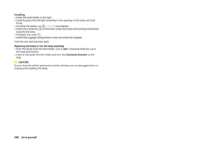 145
145 146
146 147
147 148
148 149
149 150
150 151
151 152
152 153
153 154
154 155
155 156
156 157
157 158
158 159
159 160
160 161
161 162
162 163
163