Page 185 of 240

Emergencies
Wheel change Preparation work –
If you have a flat tyre or puncture, park the
vehicle as far away from the flow of traffic
as possible. Choose a location that is as
level as possible.
– All vehicle occupants should leave the ve-
hicle. They should wait in a safe area (for
instance behind the roadside crash barri-
er).
– Switch the engine off. Switch the hazard
warning lights on and place the warning tri-
angles in position.
– Apply the handbrake
firmly.
– En g
age the first gear , or put
the selector
lever to position P for those vehicles with
an automatic gearbox.
– If you are towing a trailer, unhitch it from
your vehicle.
– Take the vehicle tools and the spare wheel
out of
the luggage compartment. WARNING
● Switch on the hazard warning lights and
place the warning triangles in position. This
is for your own safety and also warns other
road users. ●
If you change the wheel on a slope, block
the wheel on the opposite side of the car with
a stone or similar to prevent the vehicle from
moving. Changing a wheel
Change the wheel as described below:
– Remove the hub caps or the integral trim .
– Sl ac
ken the wheel bolts .
– Rai
se the vehicle with the jack at the corre-
s pondin
g area.
– Remove the wheel and put on the spare
one.
– Lower the vehicle.
– Tighten the wheel
bolts firmly with the box
sp
anner.
– Replace the hub cap.
Aft
er changing a wheel –
Put the tools back in their storage location.
– Place the wheel with the defective tyre in
the luggage compartment and secure it.
– Check the tyre pressure of the newly fitted
tyre as soon as possible. –
Have the tightening torque of the wheel
bolts checked as soon as possible with a
torque wrench. The prescribed torque must
be 120 Nm. Note
● If you notice that the wheel bolts are corro-
ded and difficult to turn when changing a
wheel, they must be replaced before having
the wheel bolt tightening torque checked.
● For safety reasons, drive at moderate
speeds until the wheel bolt tightening torque
has been checked. Wheel covers*
Fig. 158
Remove the wheel cover. The wheel covers must be removed for access
to the wheel bolts.
»
183
Technical specifications
Advice
Operation
Safety
The essentials
Page 186 of 240

Advice
Removing
– Remove the wheel cover using the wire
hook ››› Fig. 158 .
– Hook thi
s into one of the cut-outs of the
wheel cover.
Fitting
– Fit the wheel cover onto the wheel rim by
pressing it firmly. Put pressure initially on
the point of the cut-out for the valve. Next
fit the rest of the hubcap
Loosening the wheel bolts Fig. 159
Changing a wheel: loosen the wheel
bolts. The wheel bolts must be loosened before
raising the vehicle. Loosening
– Fit the box spanner as far as it will go over
the wheel bolt.
– Grasp the box spanner by the end turn it
about one full turn to the left
›
›› Fig. 159
.
Tightening
– Fit the box spanner as far as it will go over
the wheel bolt.
– Grasp the box spanner close to the end and
turn the bolt to the right until it is secured.
– An adapter is required to unscrew or tight-
en the anti-theft wheel bolts. WARNING
Loosen the wheel bolts (only about one turn)
before raising the vehicle with the jack, oth-
erwise there is a risk of accident. Note
● If the wheel bolt is very tight, you may be
able to loosen it by pushing the end of the
spanner down carefully with your foot. Hold
on to the vehicle for support and take care
not to slip. Raising the vehicle
Fig. 160
Jack position points Fig. 161
Fitting the jack. Read the additional information carefully
››› page 27
In order to remove the wheel, the vehicle
must be raised with a jack.
– Locate the jacking point under the door sill
closest to the punctured wheel ››› Fig. 160 .
184
Page 187 of 240

Emergencies
– Place the jack under the jacking point and
turn the crank until the arm of the jack is di-
rectly below the vertical rib under the door
sill.
– Align the jack so that the arm of the jack
fits around the rib under the door sill and
the movable base plate of the jack is flat on
the ground ››› Fig. 161 .
– Rai
se the vehicle until the defective wheel
is just clear of the ground.
Recesses at the front and rear of the door
sills mark the jacking points ››› Fig. 160.
There i
s only one jacking point for each
wheel. Do not fit the jack anywhere else.
An
unstable surface under the jack may
cause the vehicle to slip off the jack. There-
fore, it must be fitted on solid ground offer-
ing good support. Use a large and stable
base, if necessary. On a hard, slippery sur-
face (such as tile) use a rubber mat or similar
to prevent the jack from slipping. WARNING
● Take all precautions so that the base of the
jack does not slip. Failure to follow this in-
struction could result in an accident.
● The vehicle can be damaged if the jack is
not applied at the correct jacking points.
There is also a risk of injury since the jack can
slip off suddenly if it is not properly engaged. Removing and fitting the wheel
Change the wheel as described below after
loosening the wheel bolts and raising the ve-
hicle with the jack.
Removing a wheel
– Unscrew the wheel bolts using the box
spanner and place them on a clean surface.
Fitting a wheel
– Screw on the wheel bolts in position and
tighten them loosely with a box spanner.
The wheel bolts should be clean and easily
screwed. Before fitting the spare wheel, in-
spect the wheel condition and hub mounting
surfaces. These surfaces must be clean be-
fore fitting the wheel.
If tyres with a specific direction of rotation
are fitted, note the direction of rotation. Anti-theft wheel bolts* Fig. 162
Anti-theft wheel bolt with cap and
adapter. A special adapter is required to turn the anti-
theft wheel bolts. This is found in the tool
box.
– Insert the adapter onto the wheel bolt and
push it on as far as it will go ››› Fig. 162 .
– Fit the bo
x spanner as far as it will go over
the adapter.
– Loosen or tighten the wheel bolt as appro-
priate.
Code
The code number of the anti-theft wheel bolt
is stamped onto the front part of the adaptor.
The code number should be noted and kept
in a safe place, as it is only by using the code
number that a duplicate adaptor can be ob-
tained from SEAT Official Services. 185
Technical specifications
Advice
Operation
Safety
The essentials
Page 188 of 240

Advice
Tyres with directional tread pattern A directional tread pattern can be identified
by arrows on the sidewall that point in the di-
rection of rotation. Always note the direction
of rotation indicated when fitting the wheel.
This is important so that these tyres can give
maximum grip and avoid excessive noise,
tread wear and aquaplaning.
If, in an emergency, you have to mount the
spare wheel so it rotates in the wrong direc-
tion, you must drive extremely carefully. The
tyre will not give optimum performance. This
is particularly important when driving on wet
roads.
To benefit from the advantages of tyres with
this type of tread pattern, the defective tyre
should be replaced as soon as possible so
that all tyres again rotate in the correct direc-
tion.
Tyre repair TMS (Tyre Mobility System)* Read the additional information carefully
››› page 26
The Anti-puncture kit* (Tyre Mobility System)
will reliably seal punctures caused by the
penetration of a foreign body of up to about 4 mm in diameter. Do not remove foreign ob-
jects, e.g. screws or nails, from the tyre.
After inserting the sealant residue in the tyre,
you must again check the tyre pressure about
10 minutes after starting the engine.
You should only use the tire mobility set if
the vehicle is parked in a safe place, you are
familiar with the procedure and you have the
necessary tire mobility set! Otherwise, you
should seek professional assistance.
The tyre sealant must not be used in the
following cases:
● If the wheel rim has been damaged.
● In outside temperatures below -20 °C
(-4 °F).
● In the event of cuts or perforations in the
tyre greater than 4 mm.
● If you have been driving with very low pres-
sure or a completely flat tyre.
● If the sealant bottle has passed its use by
date. WARNING
Using the tyre mobility system can be dan-
gerous, especially when filling the tyre at the
roadside. Please observe the following rules
to minimise the risk of injury:
● Stop the vehicle safely as soon as possible.
Park it at a safe distance from surrounding
traffic to fill the tyre. ●
Ensure the ground on which you park is flat
and solid.
● All passengers and particularly children
must keep a safe distance from the work area.
● Turn on the hazard warning lights to warn
other road users.
● Use the tyre mobility system only if you are
familiar with the necessary procedures. Oth-
erwise, you should seek professional assis-
tance.
● The tyre mobility set is intended for tempo-
rary emergency use only until you can reach
the nearest specialised workshop.
● Replace the repaired tyre with the tire mo-
bility set as soon as possible.
● The sealant is a health hazard and must be
cleaned immediately if it comes into contact
with the skin.
● Always keep the tire mobility set out of the
reach of small children.
● Never use an equivalent jack, even if it has
been approved for your vehicle.
● Always stop the engine, apply the hand-
brake lever firmly and engage gear if using a
manual gearbox, in order to reduce the risk of
vehicle involuntary movement. WARNING
A tyre filled with sealant does not have the
same performance properties as a conven-
tional tyre.
● Never drive faster than 80 km/h (50 mph). 186
Page 189 of 240
 and then check
the tyre. For the sake of the environment")
Emergencies
●
Avoid heavy acceleration, hard braking and
fast cornering.
● Drive for only 10 minutes at a maximum
speed of 80 km/h (50 mph) and then check
the tyre. For the sake of the environment
Dispose of used or expired sealant observing
any legal requirements. Note
● A new bottle of sealant can be purchased at
SEAT dealerships.
● Take into account the separate instruction
manual of the tyre mobility set* manufactur-
er. Contents of the tyre mobility system*
Fig. 163
Standard representation: Contents
of the tyre mobility system. The tyre mobility set is located underneath
the floor covering in the luggage compart-
ment. It includes the following components
››› Fig. 163 :
T y
re valve remover
Sticker indicating maximum speed “max.
80 km/h” or “max. 50 mph”
Filler tube with cap
Air compressor
Tube for inflating tyres
Warning provided by tyre pressure moni-
toring system (it can also be integrated in
the compressor).
1 2
3
4
5
6 Air bleed screw (in its place, the compres-
sor may have a button).
ON/OFF switch
12 volt connector
Bottle of sealant
Spare tyre valve
The valve insert remover
1 has a gap at the
lower end for a valve insert. The valve insert
can only be screwed or unscrewed in this
way. This also applies to its replacement part 11 .
WARNING
When inflating the wheel, the air compressor
and the inflator tube may become hot.
● Protect hands and skin from hot parts.
● Do not place the hot flexible inflator tube or
hot air compressor on flammable material.
● Allow them to cool before storing the de-
vice.
● If it is not possible to inflate the tyre to at
least 2.0 bars (29 psi / 200 kPa), the tyre is
too badly damaged. The sealant is not in a
good condition to seal the tyre. Do not con-
tinue driving. Seek specialist assistance. CAUTION
Switch off the air compressor after a maxi-
mum of 8 operational minutes to avoid over-
heating! Before switching on the air compres-
sor again, let it cool for several minutes. 7
8
9
10
11
187
Technical specifications
Advice
Operation
Safety
The essentials
Page 190 of 240
 and lower:
● Stop the vehicle! Th")
Advice
Check after 10 minutes of driving Screw in the inflator tube
››› Fig. 163 5 again and check the pressure on the gauge
6 .
1.3 bar (19 psi / 130 kPa) and lower:
● Stop the vehicle! The tyre cannot be sealed
sufficiently with the tyre mobility set.
● You should obtain professional assistance
››› .
1.4 bar (20 psi / 140 kPa) and higher:
● Set the tyre pressure to the correct value
again.
● Carefully resume your journey until you
reach the nearest specialised workshop with-
out exceeding 80 km/h (50 mph).
● Have the damaged tyre replaced. WARNING
Driving with an unsealed tyre is dangerous
and can cause accidents and serious injury.
● Do not continue driving if the tyre pressure
is 1.3 bar (19 psi / 130 kPa) and lower.
● Seek specialist assistance. Jump-starting
Jump leads The jump lead must have a sufficient wire
cross section.
If the engine fails to start because of a dis-
charged battery, the battery can be connec-
ted to the battery of another vehicle to start
the engine.
Jump leads
Jump leads must comply with standard
DIN
72553 (see cable manufacturer's instruc-
tion s).
The wire cross section must be at least
25 mm 2
for petrol engines and at least
35 mm 2
for diesel engines. Note
● The vehicles must not touch each other,
otherwise electricity could flow as soon as
the positive terminals are connected.
● The discharged battery must be properly
connected to the on-board network. How to jump start: description
Fig. 164
Diagram of connections for vehicles
without Start-Stop system. Fig. 165
Diagram of connections for vehicles
with Start-Stop system. Jump lead terminal connections
1. Switch off the ignition of both vehicles
››› .
188
Page 191 of 240

Emergencies
2. Connect one end of the red jump lead to
the po s
itive + terminal of the vehicle
with the flat battery A
››› Fig. 164 .
3. C
onnect the other end of the red
jump
lead to the positive terminal + in the ve-
hicle providing assistance B .
4. For vehicles without Start-Stop system:
connect one end of the black jump lead to
the negative terminal – of the vehicle
providing the current B
››› Fig. 164 .
– For
vehicles with Start-Stop system: con-
nect one end of the black jump lead X to a
suitable ground terminal, to a solid piece of
metal in the engine block, or to the engine
block itself ››› Fig. 165 .
5. C
onnect the other end of the black jump
lead X to a solid metal component bolted
to the engine block or to the engine block
itself of the vehicle with the flat battery.
Do not connect it to a point near the bat-
tery A .
6. Position the leads in such a way that they cannot come into contact with any moving
parts in the engine compartment.
Starting
7. Start the engine of the vehicle with the boosting battery and let it run at idling
speed. 8. Start the engine of the vehicle with the flat
battery and wait 2 or 3 minutes until the
engine is “running”.
Removing the jump leads
9. Before you remove the jump leads, switch off the dipped beam headlights (if they
are switched on).
10. Turn on the heater blower and heated rear window in the vehicle with the flat
battery. This helps minimise voltage peaks
which are generated when the leads are
disconnected.
11. When the engine is running, disconnect
the l e
ads in reverse order to the details
given above.
Connect the battery clamps so they have
good metal-to-metal contact with the battery
terminals.
If the engine fails to start, switch off the start-
er after about 10 seconds and try again after
about a minute. WARNING
● Please note the safety warnings referring to
working in the engine compartment
››› page 166, Working in the engine compart-
ment.
● The b att
ery providing assistance must have
the same voltage as the flat battery (12 V)
and approximately the same capacity (see imprint on battery). Failure to comply could
result in an explosion.
●
Never use jump leads when one of the bat-
teries is frozen. Danger of explosion! Even af-
ter the battery has thawed, battery acid could
leak and cause chemical burns. If a battery
freezes, it should be replaced.
● Keep sparks, flames and lighted cigarettes
away from batteries, danger of explosion.
Failure to comply could result in an explo-
sion.
● Observe the instructions provided by the
manufacturer of the jump leads.
● Do not connect the negative cable from the
other vehicle directly to the negative terminal
of the flat battery. The gas emitted from the
battery could be ignited by sparks. Danger of
explosion.
● Do not attach the negative cable from the
other vehicle to parts of the fuel system or to
the brake line.
● The non-insulated parts of the battery
clamps must not be allowed to touch. The
jump lead attached to the positive battery
terminal must not touch metal parts of the ve-
hicle, this can cause a short circuit.
● Position the leads in such a way that they
cannot come into contact with any moving
parts in the engine compartment.
● Do not lean on the batteries. This could re-
sult in chemical burns. » 189
Technical specifications
Advice
Operation
Safety
The essentials
Page 192 of 240

Advice
Note
The vehicles must not touch each other, oth-
erwise electricity could flow as soon as the
positive terminals are connected. Towing or tow starting
Tow-starting* We recommend that you do
not tow-start your
v ehic
le. Jump-starting is preferable
››› page 188.
Ho w
ever, if your vehicle has to be tow-
started:
– Engage 2 nd
or 3 rd
gear.
– Keep the clutch pressed down.
– Switch the ignition on.
– Once both vehicles are moving, release the
clutch.
– As soon as the engine starts, press the
clutch and move the gear lever into neutral.
This helps to prevent driving into the tow-
ing vehicle. WARNING
The risk of accidents is high when tow-start-
ing. The vehicle being towed can easily col-
lide with the towing vehicle. CAUTION
When tow-starting, fuel could enter the cata-
lytic converter and damage it. Comments
Please observe the following points if you
use a tow rope:
Notes for the driver of the towing vehicle
– Drive slowly at first until the tow rope is
taut. Then accelerate gradually.
– Begin and change gears cautiously. If you
are driving an automatic vehicle, accelerate
gently.
– Remember that the brake servo and power
steering are not working in the vehicle you
are towing. Brake sooner than normal and
pressing the pedal gently.
Notes for the driver of the towed vehicle
– Ensure that the tow rope remains taut at all
times when towing.
Tow rope or tow bar
It is easier and safer for the vehicle to be tow-
ed using a tow bar. You should only use a
tow-rope if you do not have a tow-bar.
A tow rope should be slightly elastic to re-
duce the loading on both vehicles. It is advis- able to use a tow rope made of synthetic fi-
bre or similarly elastic material.
Attach the tow rope or the tow bar only to the
towline anchorages provided or a towing
bracket.
Driving style
Towing requires some experience, especially
when using a tow rope. Both drivers should
be familiar with the technique required for
towing. Inexperienced drivers should not at-
tempt to tow.
Do not pull too hard with the towing vehicle
and take care to avoid jerking the tow rope.
When towing on an unpaved road, there is al-
ways a risk of overloading and damaging the
anchorage points.
The ignition of the vehicle being towed must
be switched on to prevent the steering wheel
from locking and also to allow the use of the
turn signals, horn, windscreen wipers and
washers.
The brake servo only works when the engine
is running. When not running, you must ap-
ply considerably more pressure to the brake
pedal.
As the power assisted steering does not work
if the engine is not running, you will need
more strength to steer than you normally
would.
190
 1
1 2
2 3
3 4
4 5
5 6
6 7
7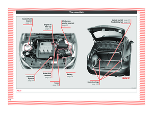 8
8 9
9 10
10 11
11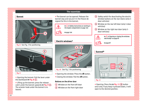 12
12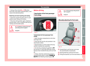 13
13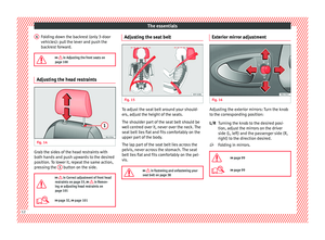 14
14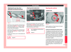 15
15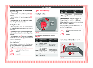 16
16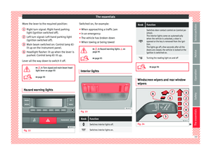 17
17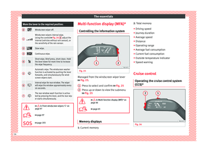 18
18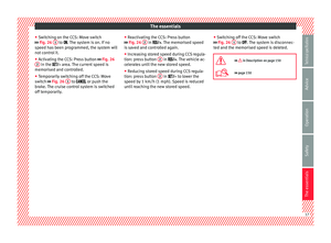 19
19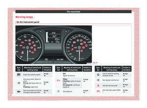 20
20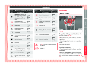 21
21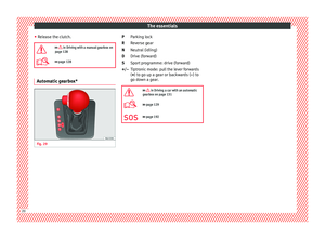 22
22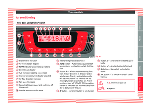 23
23 24
24 25
25 26
26 27
27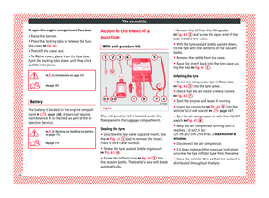 28
28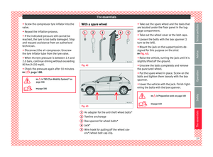 29
29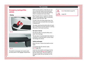 30
30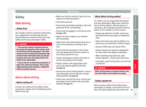 31
31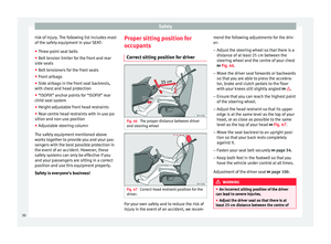 32
32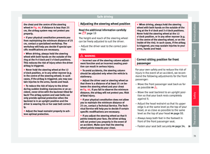 33
33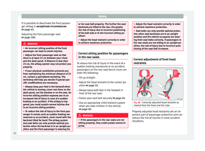 34
34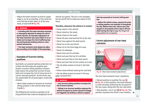 35
35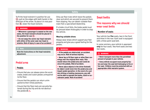 36
36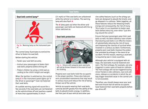 37
37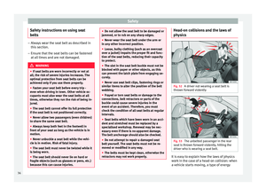 38
38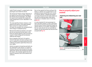 39
39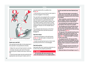 40
40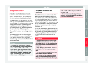 41
41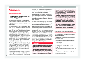 42
42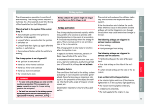 43
43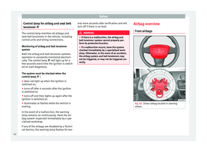 44
44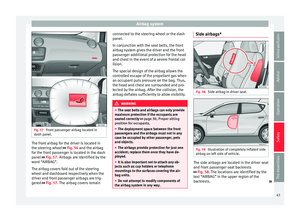 45
45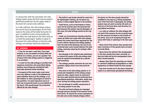 46
46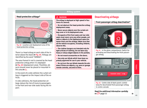 47
47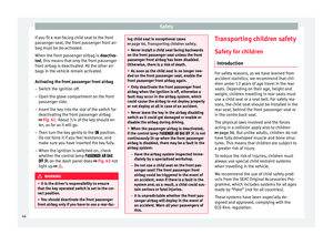 48
48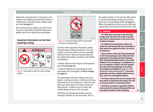 49
49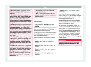 50
50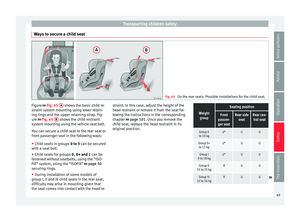 51
51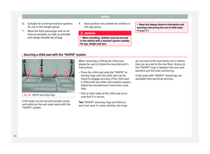 52
52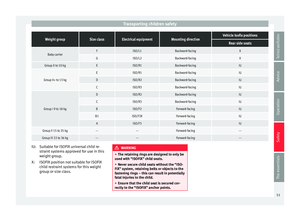 53
53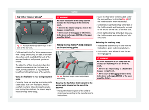 54
54 55
55 56
56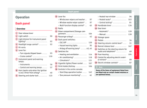 57
57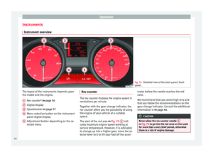 58
58 59
59 60
60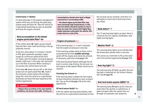 61
61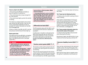 62
62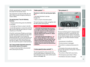 63
63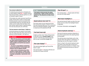 64
64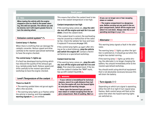 65
65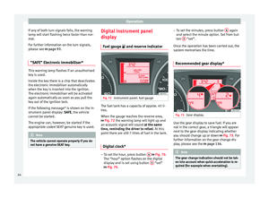 66
66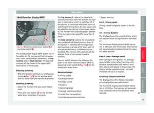 67
67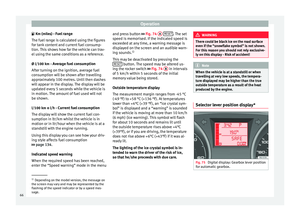 68
68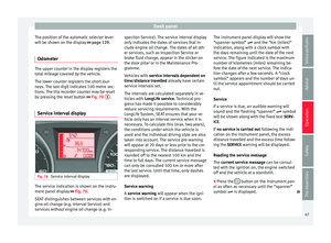 69
69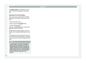 70
70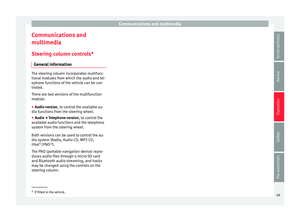 71
71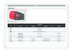 72
72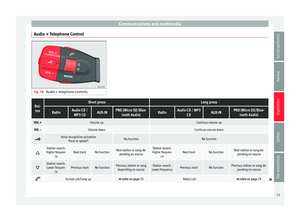 73
73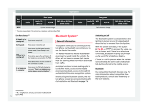 74
74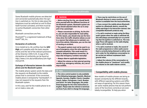 75
75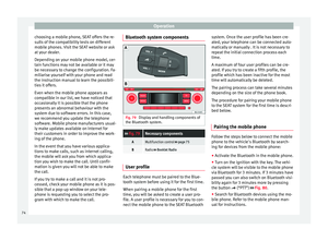 76
76 77
77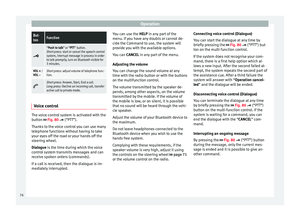 78
78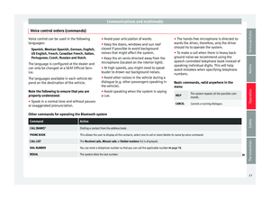 79
79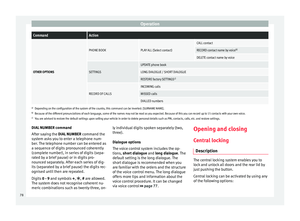 80
80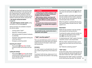 81
81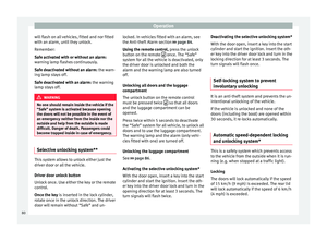 82
82 83
83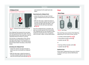 84
84 85
85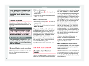 86
86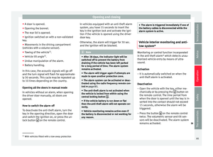 87
87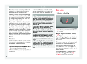 88
88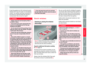 89
89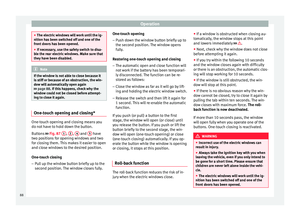 90
90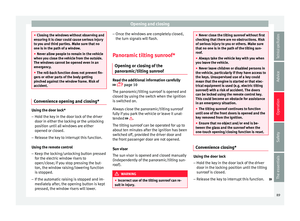 91
91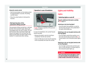 92
92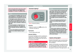 93
93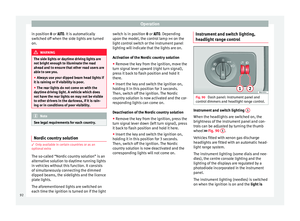 94
94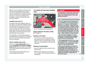 95
95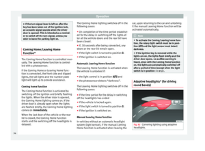 96
96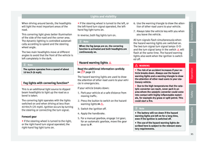 97
97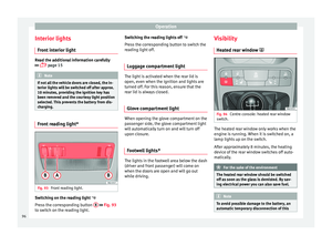 98
98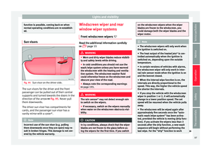 99
99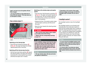 100
100 101
101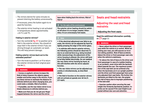 102
102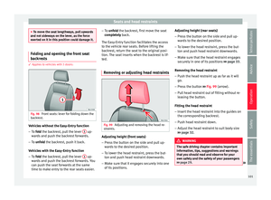 103
103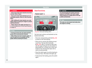 104
104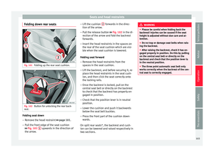 105
105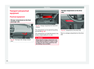 106
106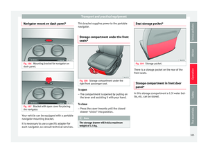 107
107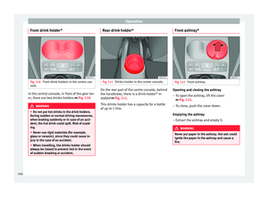 108
108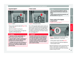 109
109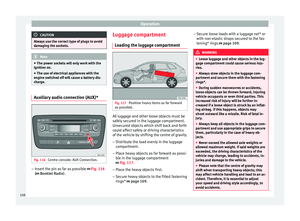 110
110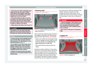 111
111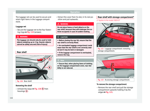 112
112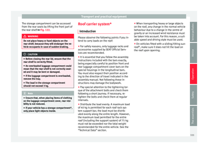 113
113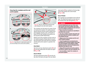 114
114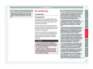 115
115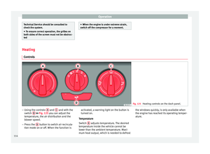 116
116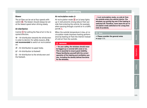 117
117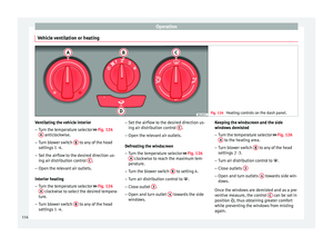 118
118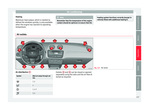 119
119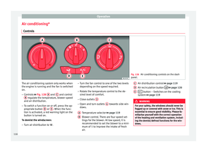 120
120 121
121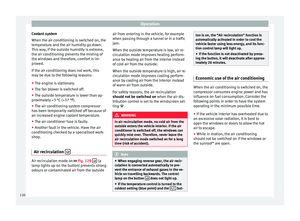 122
122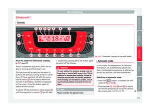 123
123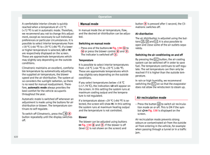 124
124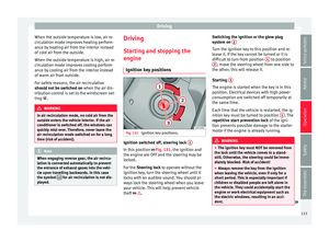 125
125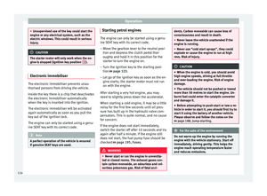 126
126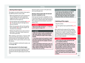 127
127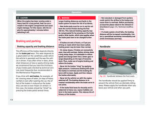 128
128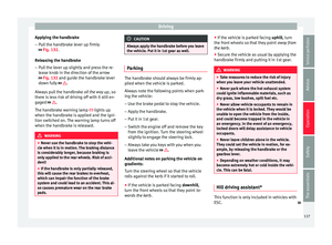 129
129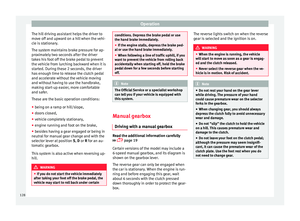 130
130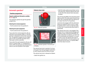 131
131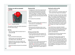 132
132 133
133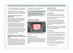 134
134 135
135 136
136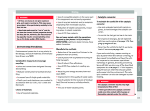 137
137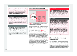 138
138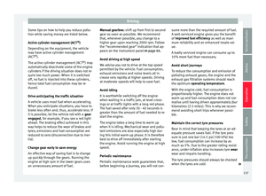 139
139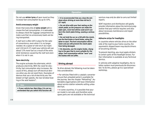 140
140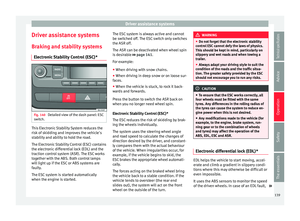 141
141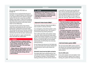 142
142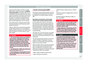 143
143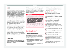 144
144 145
145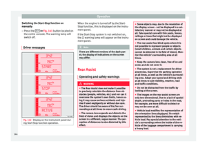 146
146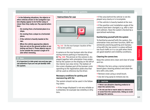 147
147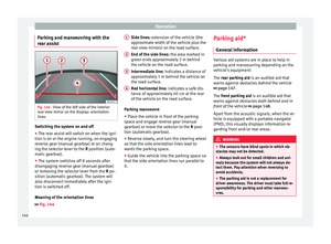 148
148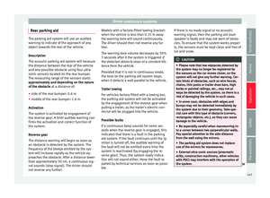 149
149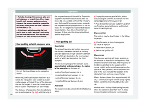 150
150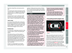 151
151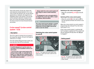 152
152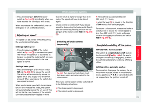 153
153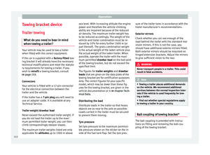 154
154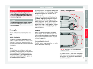 155
155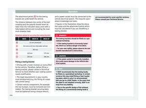 156
156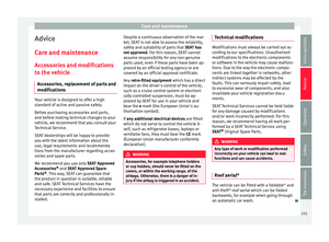 157
157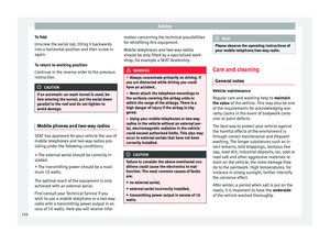 158
158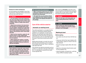 159
159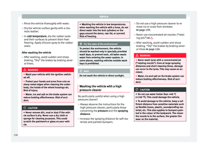 160
160 161
161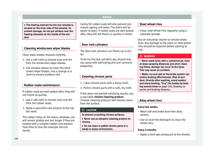 162
162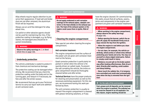 163
163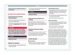 164
164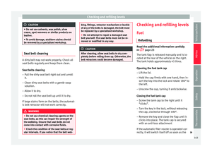 165
165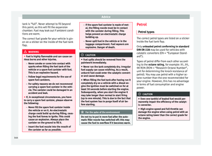 166
166 167
167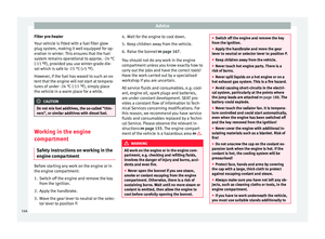 168
168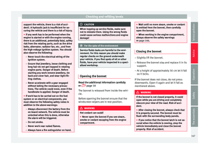 169
169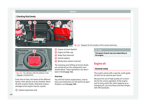 170
170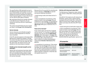 171
171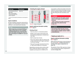 172
172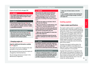 173
173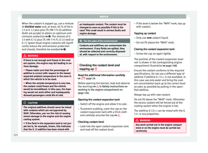 174
174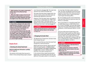 175
175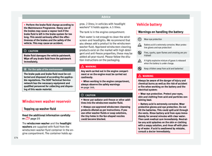 176
176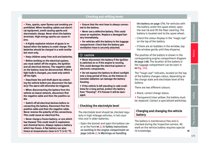 177
177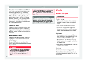 178
178 179
179 180
180 181
181 182
182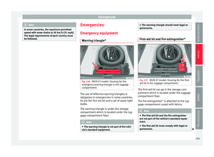 183
183 184
184 185
185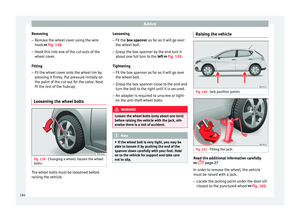 186
186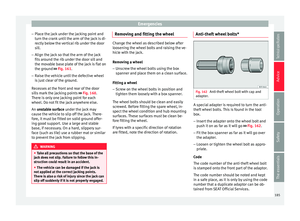 187
187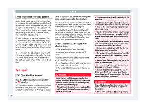 188
188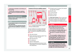 189
189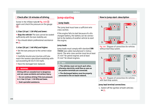 190
190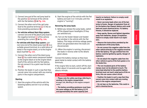 191
191 192
192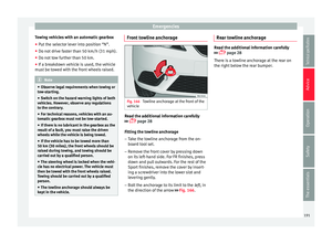 193
193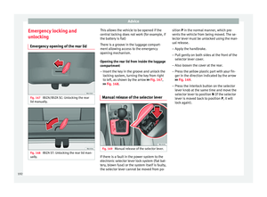 194
194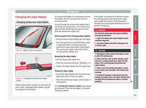 195
195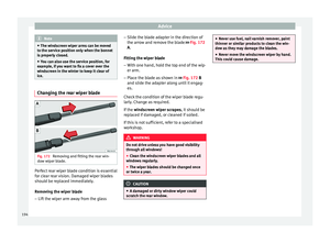 196
196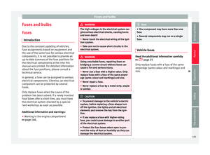 197
197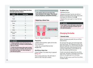 198
198 199
199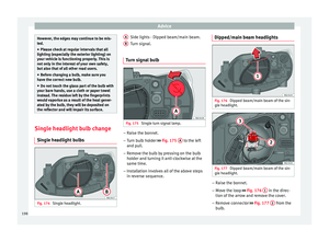 200
200 201
201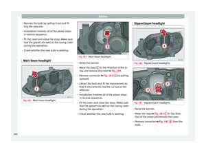 202
202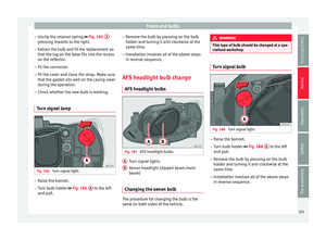 203
203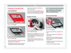 204
204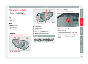 205
205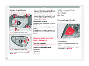 206
206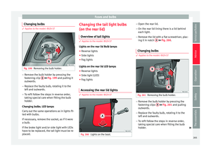 207
207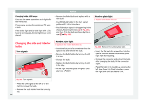 208
208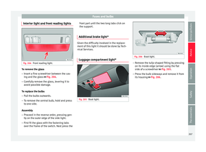 209
209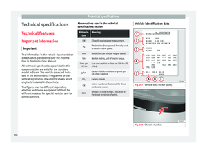 210
210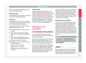 211
211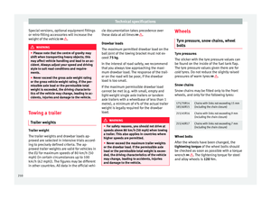 212
212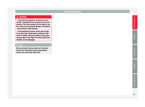 213
213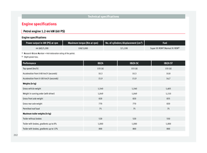 214
214 215
215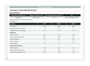 216
216 217
217 218
218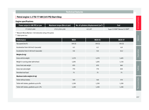 219
219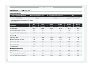 220
220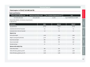 221
221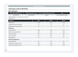 222
222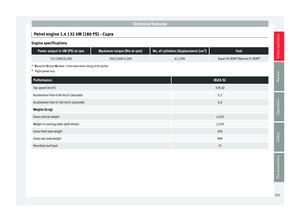 223
223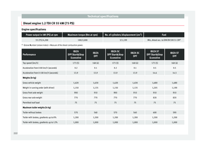 224
224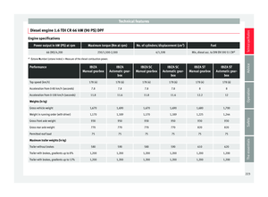 225
225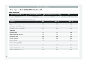 226
226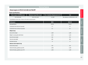 227
227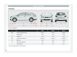 228
228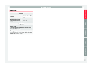 229
229 230
230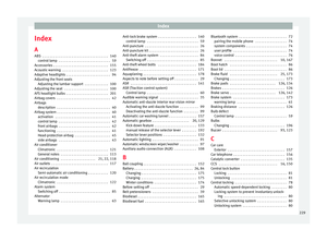 231
231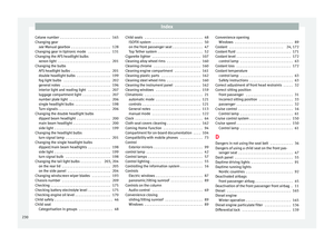 232
232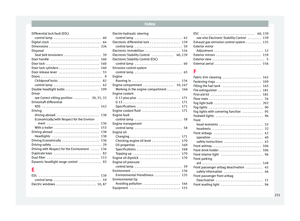 233
233 234
234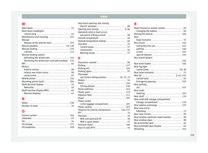 235
235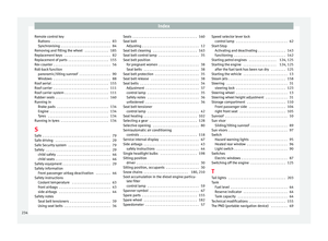 236
236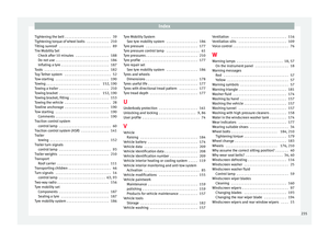 237
237 238
238 239
239