Page 4695 of 4801
WT-20
< WIRING DIAGRAM >
TIRE PRESSURE MONITORING SYSTEM
Wiring Diagram - Without Indivi dual Tire Pressure Display
INFOID:0000000009464490
ABEWA0101GB
Revision: November 20132014 Altima NAMRevision: November 20132014 Altima NAM
Page 4696 of 4801
TIRE PRESSURE MONITORING SYSTEMWT-21
< WIRING DIAGRAM >
C
D
F
G H
I
J
K L
M A
B
WT
N
O P
AAEIA0027GB
Revision: November 20132014 Altima NAMRevision: November 20132014 Altima NAM
Page 4697 of 4801
WT-22
< WIRING DIAGRAM >
TIRE PRESSURE MONITORING SYSTEM
ABEIA0228GB
Revision: November 20132014 Altima NAMRevision: November 20132014 Altima NAM
Page 4698 of 4801
TIRE PRESSURE MONITORING SYSTEMWT-23
< WIRING DIAGRAM >
C
D
F
G H
I
J
K L
M A
B
WT
N
O P
AAEIA0029GB
Revision: November 20132014 Altima NAMRevision: November 20132014 Altima NAM
Page 4705 of 4801

WT-30
< DTC/CIRCUIT DIAGNOSIS >
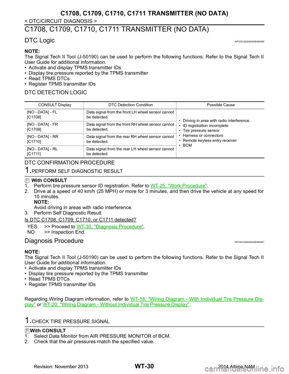
C1708, C1709, C1710, C1711 TRANSMITTER (NO DATA)
C1708, C1709, C1710, C1711 TRANSMITTER (NO DATA)
DTC LogicINFOID:0000000009464496
NOTE:
The Signal Tech II Tool (J-50190) can be used to perform the following functions. Refer to the Signal Tech II
User Guide for additional information.
• Activate and display TPMS transmitter IDs
• Display tire pressure reported by the TPMS transmitter
• Read TPMS DTCs
• Register TPMS transmitter IDs
DTC DETECTION LOGIC
DTC CONFIRMATION PROCEDURE
1.PERFORM SELF DIAGNOSTIC RESULT
With CONSULT
1. Perform tire pressure sensor ID registration. Refer to WT-25, "Work Procedure"
.
2. Drive at a speed of 40 km/h (25 MPH) or more fo r 3 minutes, and then drive the vehicle at any speed for
10 minutes.
NOTE:
Avoid driving in areas with radio interference.
3. Perform Self Diagnostic Result.
Is DTC C1708, C1709, C1710, or C1711 detected?
YES >> Proceed to WT-30, "Diagnosis Procedure".
NO >> Inspection End.
Diagnosis ProcedureINFOID:0000000009464497
NOTE:
The Signal Tech II Tool (J-50190) can be used to perform the following functions. Refer to the Signal Tech II
User Guide for additional information.
• Activate and display TPMS transmitter IDs
• Display tire pressure reported by the TPMS transmitter
• Read TPMS DTCs
• Register TPMS transmitter IDs
Regarding Wiring Diagram information, refer to WT-14, "Wiring Diagram - With Individual Tire Pressure Dis-
play" or WT-20, "Wiring Diagram - Without Individual Tire Pressure Display".
1.CHECK TIRE PRESSURE SIGNAL
With CONSULT
1. Select Data Monitor from AIR PRESSURE MONITOR of BCM.
2. Check that the air pressures match the specified value.
CONSULT Display DTC Detectio n Condition Possible Cause
[NO - DATA] - FL
[C1708] Data signal from the front LH wheel sensor cannot
be detected. • Driving in area with radio interference.
• ID registration incomplete
• Tire pressure sensor
• Harness or connectors
• Remote keyless entry receiver
•BCM
[NO - DATA] - FR
[C1709] Data signal from the front RH wheel sensor cannot
be detected.
[NO - DATA] - RR
[C1710] Data signal from the rear RH wheel sensor cannot
be detected.
[NO - DATA] - RL
[C1711] Data signal from the rear LH wheel sensor cannot
be detected.
Revision: November 20132014 Altima NAMRevision: November 20132014 Altima NAM
Page 4719 of 4801

WT-44
< DTC/CIRCUIT DIAGNOSIS >
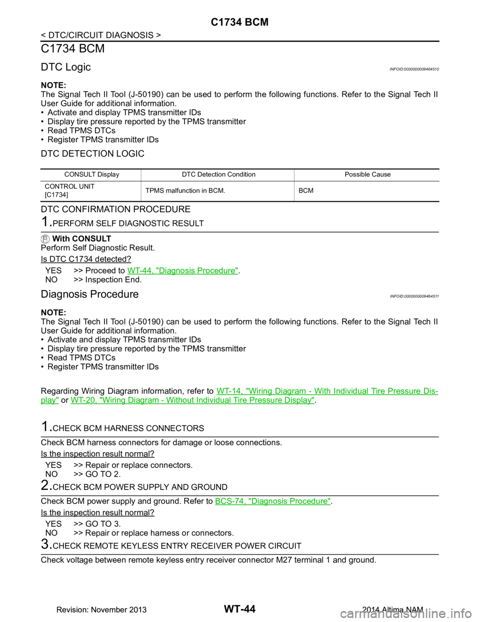
C1734 BCM
C1734 BCM
DTC LogicINFOID:0000000009464510
NOTE:
The Signal Tech II Tool (J-50190) can be used to perform the following functions. Refer to the Signal Tech II
User Guide for additional information.
• Activate and display TPMS transmitter IDs
• Display tire pressure reported by the TPMS transmitter
• Read TPMS DTCs
• Register TPMS transmitter IDs
DTC DETECTION LOGIC
DTC CONFIRMATION PROCEDURE
1.PERFORM SELF DIAGNOSTIC RESULT
With CONSULT
Perform Self Diagnostic Result.
Is DTC C1734 detected?
YES >> Proceed to WT-44, "Diagnosis Procedure".
NO >> Inspection End.
Diagnosis ProcedureINFOID:0000000009464511
NOTE:
The Signal Tech II Tool (J-50190) can be used to perform the following functions. Refer to the Signal Tech II
User Guide for additional information.
• Activate and display TPMS transmitter IDs
• Display tire pressure reported by the TPMS transmitter
• Read TPMS DTCs
• Register TPMS transmitter IDs
Regarding Wiring Diagram information, refer to WT-14, "Wiring Diagram - With Individual Tire Pressure Dis-
play" or WT-20, "Wiring Diagram - Without Individual Tire Pressure Display".
1.CHECK BCM HARNESS CONNECTORS
Check BCM harness connectors fo r damage or loose connections.
Is the inspection result normal?
YES >> Repair or replace connectors.
NO >> GO TO 2.
2.CHECK BCM POWER SUPPLY AND GROUND
Check BCM power supply and ground. Refer to BCS-74, "Diagnosis Procedure"
.
Is the inspection result normal?
YES >> GO TO 3.
NO >> Repair or replace harness or connectors.
3.CHECK REMOTE KEYL ESS ENTRY RECEIVER POWER CIRCUIT
Check voltage between remote keyless entry receiver connector M27 terminal 1 and ground.
CONSULT Display DTC Detectio n Condition Possible Cause
CONTROL UNIT
[C1734] TPMS malfunction in BCM. BCM
Revision: November 20132014 Altima NAMRevision: November 20132014 Altima NAM
Page 4736 of 4801

WW-1
DRIVER CONTROLS
C
D E
F
G H
I
J
K
M
SECTION WW
A
B
WW
N
O P
CONTENTS
WIPER & WASHER
PRECAUTION ................ ...............................3
PRECAUTIONS .............................................. .....3
Precaution for Supplemental Restraint System
(SRS) "AIR BAG" and "SEAT BELT PRE-TEN-
SIONER" ............................................................. ......
3
Precaution for Procedure without Cowl Top Cover ......3
SYSTEM DESCRIPTION ..............................4
FRONT WIPER AND WASHER SYSTEM ..... .....4
Component Parts Location .................................. ......4
Component Description ............................................5
SYSTEM ..............................................................6
System Diagram .................................................. ......6
System Description ...................................................6
Fail-Safe ....................................................................9
DIAGNOSIS SYSTEM (BCM) ............................10
COMMON ITEM ..................................................... ....10
COMMON ITEM : CONSULT Function (BCM -
COMMON ITEM) ................................................. ....
10
WIPER ................................................................... ....11
WIPER : CONSULT Function (BCM - WIPER) .......11
DIAGNOSIS SYSTEM (IPDM E/R) .....................12
Diagnosis Description ......................................... ....12
CONSULT Function (IPDM E/R) .............................13
ECU DIAGNOSIS INFORMATION ..............16
BCM, IPDM E/R .............................................. ....16
List of ECU Reference ........................................ ....16
WIRING DIAGRAM ......................................17
FRONT WIPER AND WASHER SYSTEM ..... ....17
Wiring Diagram - Without Rear View Camera
Washer Control System ...................................... ....
17
Wiring Diagram - With Rear View Camera Washer
Control System .................................................... ....
23
BASIC INSPECTION ...................................31
DIAGNOSIS AND REPAIR WORKFLOW ........31
Work Flow ............................................................ ....31
DTC/CIRCUIT DIAGNOSIS .........................33
WIPER AND WASHER FUSE ...........................33
Description ........................................................... ....33
Diagnosis Procedure ...............................................33
FRONT WIPER MOTOR LO CIRCUIT ..............34
Component Function Check ....................................34
Diagnosis Procedure ...............................................34
FRONT WIPER MOTOR HI CIRCUIT ...............36
Component Function Check ....................................36
Diagnosis Procedure ...............................................36
FRONT WIPER AUTO STOP SIGNAL CIR-
CUIT ..................................................................
38
Component Function Check ................................ ....38
Diagnosis Procedure ...............................................38
FRONT WIPER MOTOR GROUND CIRCUIT ...39
Diagnosis Procedure ...............................................39
WASHER MOTOR CIRCUIT .............................40
Diagnosis Procedure ...............................................40
WASHER SWITCH ............................................44
Description ...............................................................44
Component Inspection .............................................44
SYMPTOM DIAGNOSIS ..............................45
WIPER AND WASHER SYSTEM SYMPTOMS
...
45
Symptom Table ................................................... ....45
Revision: November 20132014 Altima NAMRevision: November 20132014 Altima NAM
Page 4752 of 4801
FRONT WIPER AND WASHER SYSTEMWW-17
< WIRING DIAGRAM >
C
D E
F
G H
I
J
K
M A
B
WW
N
O P
WIRING DIAGRAM
FRONT WIPER AND WASHER SYSTEM
Wiring Diagram - Without Rear Vi ew Camera Washer Control SystemINFOID:0000000009464609
ABLWA2233GB
Revision: November 20132014 Altima NAMRevision: November 20132014 Altima NAM