2014 NISSAN TEANA key battery
[x] Cancel search: key batteryPage 2575 of 4801

SERVICE INFORMATION FOR ELECTRICAL INCIDENTGI-47
< BASIC INSPECTION >
C
D E
F
G H
I
J
K L
M B
GI
N
O P
no voltage; open is between fuse block and SW1 (point A).
• Close SW1 and probe at relay. voltage; open is further down the circuit than the relay.
no voltage; open is between SW1 and relay (point B).
• Close the relay and probe at the solenoid. voltage; open is further down the circuit than the solenoid.
no voltage; open is between relay and solenoid (point C).
Any powered circuit can be diagnosed using the approach in the previous example.
TESTING FOR “SHORTS” IN THE CIRCUIT
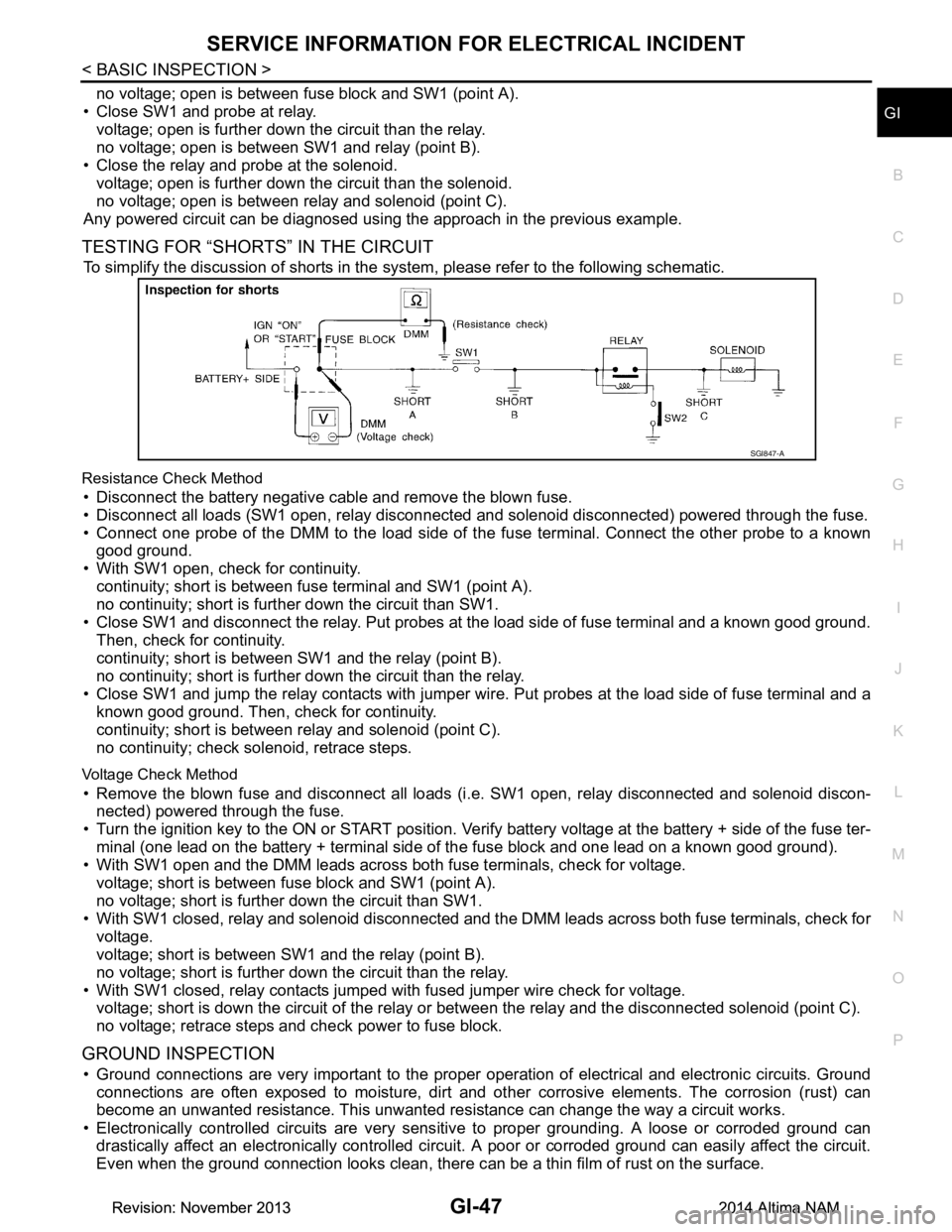
To simplify the discussion of shorts in the system, please refer to the following schematic.
Resistance Check Method
• Disconnect the battery negative cable and remove the blown fuse.
• Disconnect all loads (SW1 open, relay disconnected and solenoid disconnected) powered through the fuse.
• Connect one probe of the DMM to the load side of the fuse terminal. Connect the other probe to a known
good ground.
• With SW1 open, check for continuity. continuity; short is between fuse terminal and SW1 (point A).
no continuity; short is further down the circuit than SW1.
• Close SW1 and disconnect the relay. Put probes at the load side of fuse terminal and a known good ground. Then, check for continuity.
continuity; short is between SW1 and the relay (point B).
no continuity; short is further down the circuit than the relay.
• Close SW1 and jump the relay contacts with jumper wir e. Put probes at the load side of fuse terminal and a
known good ground. Then, check for continuity.
continuity; short is between relay and solenoid (point C).
no continuity; check solenoid, retrace steps.
Voltage Check Method
• Remove the blown fuse and disconnect all loads (i .e. SW1 open, relay disconnected and solenoid discon-
nected) powered through the fuse.
• Turn the ignition key to the ON or START position. Veri fy battery voltage at the battery + side of the fuse ter-
minal (one lead on the battery + terminal side of the fuse block and one lead on a known good ground).
• With SW1 open and the DMM leads across both fuse terminals, check for voltage.
voltage; short is between fuse block and SW1 (point A).
no voltage; short is further down the circuit than SW1.
• With SW1 closed, relay and solenoid disconnected and t he DMM leads across both fuse terminals, check for
voltage.
voltage; short is between SW1 and the relay (point B).
no voltage; short is further down the circuit than the relay.
• With SW1 closed, relay contacts jumped with fused jumper wire check for voltage. voltage; short is down the circuit of the relay or between the relay and the disconnected solenoid (point C).
no voltage; retrace steps and check power to fuse block.
GROUND INSPECTION
• Ground connections are very important to the proper operation of electrical and electronic circuits. Ground
connections are often exposed to moisture, dirt and ot her corrosive elements. The corrosion (rust) can
become an unwanted resistance. This unwanted re sistance can change the way a circuit works.
• Electronically controlled circuits are very sens itive to proper grounding. A loose or corroded ground can
drastically affect an electronically controlled circuit. A poor or corroded ground can easily affect the circuit.
Even when the ground connection looks clean, there c an be a thin film of rust on the surface.
SGI847-A
Revision: November 20132014 Altima NAMRevision: November 20132014 Altima NAM
Page 2773 of 4801
![NISSAN TEANA 2014 Service Manual
HAC-124
< SYSTEM DESCRIPTION >[MANUAL AIR CONDITIONER]
DIAGNOSIS SYSTEM (BCM)
DIAGNOSIS SYSTEM (BCM)
CONSULT Function (BCM - COMMON ITEM)INFOID:0000000009958322
CAUTION:
After disconnecting the CONS NISSAN TEANA 2014 Service Manual
HAC-124
< SYSTEM DESCRIPTION >[MANUAL AIR CONDITIONER]
DIAGNOSIS SYSTEM (BCM)
DIAGNOSIS SYSTEM (BCM)
CONSULT Function (BCM - COMMON ITEM)INFOID:0000000009958322
CAUTION:
After disconnecting the CONS](/manual-img/5/57390/w960_57390-2772.png)
HAC-124
< SYSTEM DESCRIPTION >[MANUAL AIR CONDITIONER]
DIAGNOSIS SYSTEM (BCM)
DIAGNOSIS SYSTEM (BCM)
CONSULT Function (BCM - COMMON ITEM)INFOID:0000000009958322
CAUTION:
After disconnecting the CONSULT vehicle interface (VI) from the data link connector, the ignition must
be cycled OFF → ON (for at least 5 seconds) → OFF. If this step is not performed, the BCM may not go
to ”sleep mode”, potentially causing a di scharged battery and a no-start condition.
APPLICATION ITEM
CONSULT performs the following functions via CAN communication with BCM.
SYSTEM APPLICATION
BCM can perform the following functions.
Direct Diagnostic Mode Description
Ecu Identification The BCM part number is displayed.
Self Diagnostic Result The BCM self diagnostic results are displayed.
Data Monitor The BCM input/output data is displayed in real time.
Active Test The BCM activates outputs to test components.
Work support The settings for BCM functions can be changed.
Configuration • The vehicle specification can be read and saved.
• The vehicle specification can be written when replacing BCM.
CAN Diag Support Mntr The result of transmit/receive diagnosis of CAN communication is displayed.
System Sub System Direct Diagnostic Mode
Ecu Identification
Self Diagnostic Result
Data Monitor
Active Test
Work support
Configuration
CAN Diag Support Mntr
Door lock DOOR LOCK ××××
Rear window defogger REAR DEFOGGER ×××
Warning chime BUZZER ××
Interior room lamp timer INT LAMP ×××
Remote keyless entry system MULTI REMOTE ENT ×××
Exterior lamp HEADLAMP ×××
Wiper and washer WIPER ×××
Turn signal and hazard warning lamps FLASHER ××
Air conditioner AIR CONDITIONER ×
Intelligent Key system INTELLIGENT KEY ××××
Combination switch COMB SW ×
BCM BCM × × ×××
Immobilizer IMMU ×××
Interior room lamp battery saver BATTERY SAVER ××
Trunk open TRUNK ×
Vehicle security system THEFT ALM ×××
RAP system RETAINED PWR ×
Revision: November 20132014 Altima NAMRevision: November 20132014 Altima NAM
Page 2822 of 4801

INL-1
DRIVER CONTROLS
C
D E
F
G H
I
J
K
M
SECTION INL
A
B
INL
N
O P
CONTENTS
INTERIOR LIGHTING SYSTEM
PRECAUTION ................ ...............................3
PRECAUTIONS .............................................. .....3
Precaution for Supplemental Restraint System
(SRS) "AIR BAG" and "SEAT BELT PRE-TEN-
SIONER" ............................................................. ......
3
Precaution for Work ..................................................3
PREPARATION ............................................4
PREPARATION .............................................. .....4
Special Service Tool ........................................... ......4
SYSTEM DESCRIPTION ..............................5
COMPONENT PARTS ................................... .....5
Component Parts Location .................................. ......5
Component Description .............................................5
INTERIOR ROOM LAMP CONTROL SYSTEM
.....
7
System Diagram .................................................. ......7
System Description ...................................................7
ILLUMINATION CONTROL SYSTEM .................9
System Diagram .................................................. ......9
System Description ...................................................9
DIAGNOSIS SYSTEM (BCM) ............................11
COMMON ITEM ..................................................... ....11
COMMON ITEM : CONSULT Function (BCM -
COMMON ITEM) ................................................. ....
11
INT LAMP .............................................................. ....12
INT LAMP : CONSULT Function (BCM - INT
LAMP) ................................................................. ....
12
BATTERY SAVER ................................................. ....13
BATTERY SAVER : CONSULT Function (BCM -
BATTERY SAVER) ............ .....................................
13
INTELLIGENT KEY ............................................... ....13
INTELLIGENT KEY : CONSULT Function (BCM -
INTELLIGENT KEY) ........... .....................................
13
DIAGNOSIS SYSTEM (IPDM E/R) ...................17
Diagnosis Description .......................................... ....17
CONSULT Function (IPDM E/R) .............................18
ECU DIAGNOSIS INFORMATION ..............21
BCM, IPDM E/R .................................................21
List of ECU Reference ......................................... ....21
WIRING DIAGRAM ......................................22
INTERIOR ROOM LAMP ..................................22
Wiring Diagram .................................................... ....22
ILLUMINATION .................................................33
Wiring Diagram ........................................................33
BASIC INSPECTION ...................................47
DIAGNOSIS AND REPAIR WORKFLOW ........47
Work Flow ............................................................ ....47
DTC/CIRCUIT DIAGNOSIS .........................50
POWER SUPPLY AND GROUND CIRCUIT ....50
BCM ....................................................................... ....50
BCM : Diagnosis Procedure ....................................50
IPDM E/R ................................................................ ....50
IPDM E/R : Diagnosis Procedure ............................50
BATTERY SAVER OUTPUT/POWER SUP-
PLY CIRCUIT ....................................................
52
Description ........................................................... ....52
Component Function Check ....................................52
Diagnosis Procedure ...............................................52
INTERIOR ROOM LAMP CONTROL CIRCUIT
...
54
Description ........................................................... ....54
Revision: November 20132014 Altima NAMRevision: November 20132014 Altima NAM
Page 2828 of 4801

INTERIOR ROOM LAMP CONTROL SYSTEMINL-7
< SYSTEM DESCRIPTION >
C
D E
F
G H
I
J
K
M A
B
INL
N
O P
INTERIOR ROOM LAMP CONTROL SYSTEM
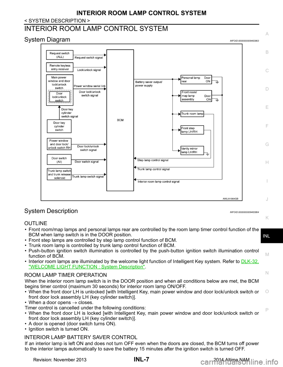
System DiagramINFOID:0000000009463863
System DescriptionINFOID:0000000009463864
OUTLINE
• Front room/map lamps and personal lamps rear are controll ed by the room lamp timer control function of the
BCM when lamp switch is in the DOOR position.
• Front step lamps are controlled by step lamp control function of BCM.
• Trunk room lamp is controlled by trunk lamp control function of BCM.
• Push-button ignition switch illumination is controlled by the push-button ignition switch illumination control
function of BCM.
• Interior room lamps are illuminated by the welcome light function of Intelligent Key system. Refer to DLK-32,
"WELCOME LIGHT FUNCTION : System Description".
ROOM LAMP TIMER OPERATION
When the interior room lamp switch is in the DOOR position and when all conditions below are met, the BCM
begins timer control (maximum 30 seconds ) for interior room lamp ON/OFF.
• When the front door LH is unlocked [with Intelligent Key, main power window and door lock/unlock switch or
front door lock assembly LH (key cylinder switch)].
• When a door opens → closes.
Timer control is cancelled under the following conditions:
• When the front door LH is locked [with Intelligent Key, main power window and door lock/unlock switch or front door lock assembly LH (key cylinder switch)].
• A door is opened (door switch turns ON).
• Ignition switch is turned ON.
INTERIOR LAMP BATTERY SAVER CONTROL
If an interior lamp is left ON and does not turn OF F even when the doors are closed, the BCM turns off power
to the interior lamps automatically to save the batte ry 15 minutes after the ignition switch is turned OFF.
AWLIA1984GB
Revision: November 20132014 Altima NAMRevision: November 20132014 Altima NAM
Page 2829 of 4801

INL-8
< SYSTEM DESCRIPTION >
INTERIOR ROOM LAMP CONTROL SYSTEM
The BCM controls the following interior lamps:
• Front step lamp LH/RH
• Front room/map lamp LH/RH
• Personal lamp rear LH/RH
• Vanity mirror lamp LH/RH (if equipped)
• Trunk room lamp
After the battery saver system turns the la mps OFF, the lamps will illuminate again when:
• A signal is received from an Intelligent Key or main power window and door lock/unlock switch or when the front door lock assembly LH (key cylinder switch) is locked or unlocked.
• A door is opened or closed.
Revision: November 20132014 Altima NAMRevision: November 20132014 Altima NAM
Page 2832 of 4801

DIAGNOSIS SYSTEM (BCM)INL-11
< SYSTEM DESCRIPTION >
C
D E
F
G H
I
J
K
M A
B
INL
N
O P
DIAGNOSIS SYSTEM (BCM)
COMMON ITEM
COMMON ITEM : CONSULT Function (BCM - COMMON ITEM)INFOID:0000000009956797
CAUTION:
After disconnecting the CONSULT vehicle interface (VI) from the data link connector, the ignition must
be cycled OFF → ON (for at least 5 seconds) → OFF. If this step is not performed, the BCM may not go
to ”sleep mode”, potentiall y causing a discharged battery and a no-start condition.
APPLICATION ITEM
CONSULT performs the following functions via CAN communication with BCM.
SYSTEM APPLICATION
BCM can perform the following functions.
Direct Diagnostic Mode Description
Ecu Identification The BCM part number is displayed.
Self Diagnostic Result The BCM self diagnostic results are displayed.
Data Monitor The BCM input/output data is displayed in real time.
Active Test The BCM activates outputs to test components.
Work support The settings for BCM functions can be changed.
Configuration • The vehicle specification can be read and saved.
• The vehicle specification can be written when replacing BCM.
CAN Diag Support Mntr The result of transmit/receive diagnosis of CAN communication is displayed.
System Sub System Direct Diagnostic Mode
Ecu Identification
Self Diagnostic Result
Data Monitor
Active Test
Work support
Configuration
CAN Diag Su pport Mntr
Door lock DOOR LOCK ××××
Rear window defogger REAR DEFOGGER ×××
Warning chime BUZZER ××
Interior room lamp timer INT LAMP ×××
Remote keyless entry system MULTI REMOTE ENT ×××
Exterior lamp HEADLAMP ×××
Wiper and washer WIPER ×××
Turn signal and hazard warning lamps FLASHER ××
Air conditioner AIR CONDITIONER ×
Intelligent Key system INTELLIGENT KEY ××××
Combination switch COMB SW ×
BCM BCM × × ×××
Immobilizer IMMU ×××
Interior room lamp battery saver BATTERY SAVER ××
Trunk open TRUNK ×
Vehicle security system THEFT ALM ×××
Revision: November 20132014 Altima NAMRevision: November 20132014 Altima NAM
Page 2833 of 4801

INL-12
< SYSTEM DESCRIPTION >
DIAGNOSIS SYSTEM (BCM)
INT LAMP
INT LAMP : CONSULT Function (BCM - INT LAMP)INFOID:0000000009956798
CAUTION:
After disconnecting the CONSULT vehicle interface (VI) from the data link connector, the ignition must
be cycled OFF → ON (for at least 5 seconds) → OFF. If this step is not performed, the BCM may not go
to ”sleep mode”, potentially causing a di scharged battery and a no-start condition.
DATA MONITOR
ACTIVE TEST
WORK SUPPORT
NOTE:
The items listed below are the only applicable Work Support it ems for this vehicle. If other items are displayed
on CONSULT, do not use or change t he setting for these other items.
RAP system RETAINED PWR ×
Signal buffer system SIGNAL BUFFER ×
TPMS AIR PRESSURE MONITOR ××××
System Sub System
Direct Diagnostic Mode
Ecu Identification
Self Diagnostic Result
Data Monitor
Active Test
Work support
Configuration
CAN Diag Support Mntr
Monitor Item [Unit] Description
REQ SW -DR [On/Off] Indicates condition of door request switch LH.
REQ SW -AS [On/Off] Indicates condition of door request switch RH.
PUSH -SW [On/Off] Indicates condition of push-button ignition switch.
UNLK SEN -DR [On/Off] Indicates condition of door unlock sensor.
DOOR SW-DR [On/Off] Indicates condition of front door switch LH.
DOOR SW-AS [On/Off] Indicates condition of front door switch RH.
DOOR SW-RR [On/Off] Indicates condition of rear door switch RH.
DOOR SW-RL [On/Off] Indicates condition of rear door switch LH.
DOOR SW-BK [On/Off] Indicates condition of trunk switch.
CDL LOCK SW [On/Off] Indicates condition of lock signal from door lock and unlock switch.
CDL UNLOCK SW [On/Off] Indicates condition of unlock signal from door lock and unlock switch.
KEY CYL LK-SW [On/Off] Indicates condition of lock signal from door key cylinder switch.
KEY CYL UN-SW [On/Off] Indicates condition of unlock signal from door key cylinder switch.
TRNK/HAT MNTR [On/Off] Indicates condition of trunk room lamp switch.
RKE-LOCK [On/Off] Indicates condition of lock signal from Intelligent Key.
RKE-UNLOCK [On/Off] Indicates condition of unlock signal from Intelligent Key.
Te s t I t e m D e s c r i p t i o n
INT LAMP This test is able to check interior room lamp operation [On/Off].
STEP LAMP TEST This test is able to check step lamp operation [On/Off].
Revision: November 20132014 Altima NAMRevision: November 20132014 Altima NAM
Page 2834 of 4801

DIAGNOSIS SYSTEM (BCM)INL-13
< SYSTEM DESCRIPTION >
C
D E
F
G H
I
J
K
M A
B
INL
N
O P
* : Initial setting
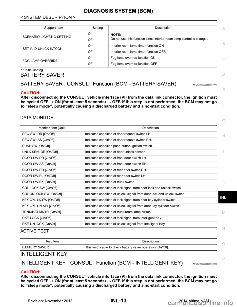
BATTERY SAVER
BATTERY SAVER : CONSULT Function (BCM - BATTERY SAVER)INFOID:0000000009956799
CAUTION:
After disconnecting the CONSULT vehicle interface (VI) from the data link connector, the ignition must
be cycled OFF → ON (for at least 5 seconds) → OFF. If this step is not performed, the BCM may not go
to ”sleep mode”, potentiall y causing a discharged battery and a no-start condition.
DATA MONITOR
ACTIVE TEST
INTELLIGENT KEY
INTELLIGENT KEY : CONSULT Func tion (BCM - INTELLIGENT KEY)INFOID:0000000009956802
CAUTION:
After disconnecting the CONSULT vehicle interface (VI) from the data link connector, the ignition must
be cycled OFF → ON (for at least 5 seconds) → OFF. If this step is not performed, the BCM may not go
to ”sleep mode”, potentiall y causing a discharged battery and a no-start condition.
Support Item Setting Description
SCENARIO LIGHTING SETTING On
NOTE:
Do not use this function since interior room lamp control is changed.
Off*
SET I/L D-UNLCK INTCON On Interior room lamp timer function ON.
Off* Interior room lamp timer function OFF.
FOG LAMP OVERRIDE On* Fog lamp override function ON.
Off Fog lamp override function OFF.
Monitor Item [Unit] Description
REQ SW -DR [On/Off] Indicates condition of door request switch LH.
REQ SW -AS [On/Off] Indicates condition of door request switch RH.
PUSH SW [On/Off] Indicates condition push-button ignition switch.
UNLK SEN -DR [On/Off] Indicates condition of door unlock sensor.
DOOR SW-DR [On/Off] Indicates condition of front door switch LH.
DOOR SW-AS [On/Off] Indicates condition of front door switch RH.
DOOR SW-RR [On/Off] Indicates condition of rear door switch RH.
DOOR SW-RL [On/Off] Indicates condition of rear door switch LH.
DOOR SW-BK [On/Off] Indicates condition of trunk switch.
CDL LOCK SW [On/Off] Indicates condition of lock signal from door lock and unlock switch.
CDL UNLOCK SW [On/Off] Indicates condition of unlock signal from door lock and unlock switch.
KEY CYL LK-SW [On/Off] Indicates condition of lo ck signal from door key cylinder switch.
KEY CYL UN-SW [On/Off] Indicates condition of unl ock signal from door key cylinder switch.
TRNK/HAT MNTR [On/Off] Indicates condition of trunk room lamp switch.
RKE-LOCK [On/Off] Indicates condition of lock signal from Intelligent Key.
RKE-UNLOCK [On/Off] Indicates condition of unlock signal from Intelligent Key.
Test item Description
BATTERY SAVER This test is able to check battery saver operation [On/Off].
Revision: November 20132014 Altima NAMRevision: November 20132014 Altima NAM