2014 NISSAN TEANA check engine
[x] Cancel search: check enginePage 2557 of 4801
PRECAUTIONSGI-29
< PRECAUTION >
C
D E
F
G H
I
J
K L
M B
GI
N
O P
To prevent ECM from storing the diagnostic trou ble codes, do not carelessly disconnect the harness
connectors which are related to the engine cont rol system and TCM (transmission control module)
system. The connectors should be disconnected only when working according to the WORK FLOW of
TROUBLE DIAGNOSES in EC and TM sections.
Three Way CatalystINFOID:0000000009462996
If a large amount of unburned fuel flows into the catalyst , the catalyst temperature will be excessively high. To
prevent this, follow the instructions.
• Use unleaded gasoline only. Leaded gasoline will seriously damage the three way catalyst.
• When checking for ignition spark or measuring engine compression, make tests quickly and only when nec- essary.
• Do not run engine when the fuel tank level is low, otherwise the engine may misfire, causing damage to the
catalyst.
Do not place the vehicle on flammable material. Keep flammable material off the exhaust pipe and the three
way catalyst.
Fuel (Regular Unleaded Ga soline Recommended) QR25DEINFOID:0000000009462997
Use unleaded regular gasoline with an octane rating of at least 87 AKI (Anti-Knock Index) number (Research
octane number 91). E-85 fuel (85% fuel ethanol, 15% unl eaded gasoline) may only be used in vehicles specif-
ically designed for E-85 fuel (i.e. Flexible Fuel Vehicle - FFV models).
CAUTION:
Do not use leaded gasoli ne. Using leaded gasoline will damage the three way catalyst. Do not use E-85
fuel (85% fuel ethanol, 15% unlead ed gasoline) unless the vehicle is specifically designed for E-85 fuel
(i.e. Flexible Fuel Vehicle - FFV models). Using a fu el other than that specified could adversely affect
the emission control devices and systems, and could also affect the warranty coverage validity.
Fuel (Regular Unleaded Gasoline Recommended) VQ35DEINFOID:0000000009462998
Use unleaded regular gasoline with an octane rating of at least 87 AKI (Anti-Knock Index) number (Research
octane number 91). E-85 fuel (85% fuel ethanol, 15% unl eaded gasoline) may only be used in vehicles specif-
ically designed for E-85 fuel (i.e. Flexible Fuel Vehicle - FFV models).
CAUTION:
Do not use leaded gasoli ne. Using leaded gasoline will damage the three way catalyst. Do not use E-85
fuel (85% fuel ethanol, 15% unlead ed gasoline) unless the vehicle is specifically designed for E-85 fuel
(i.e. Flexible Fuel Vehicle - FFV models). Using a fu el other than that specified could adversely affect
the emission control devices and systems, and could also affect the warranty coverage validity.
Multiport Fuel Injection System or Engine Control SystemINFOID:0000000009462999
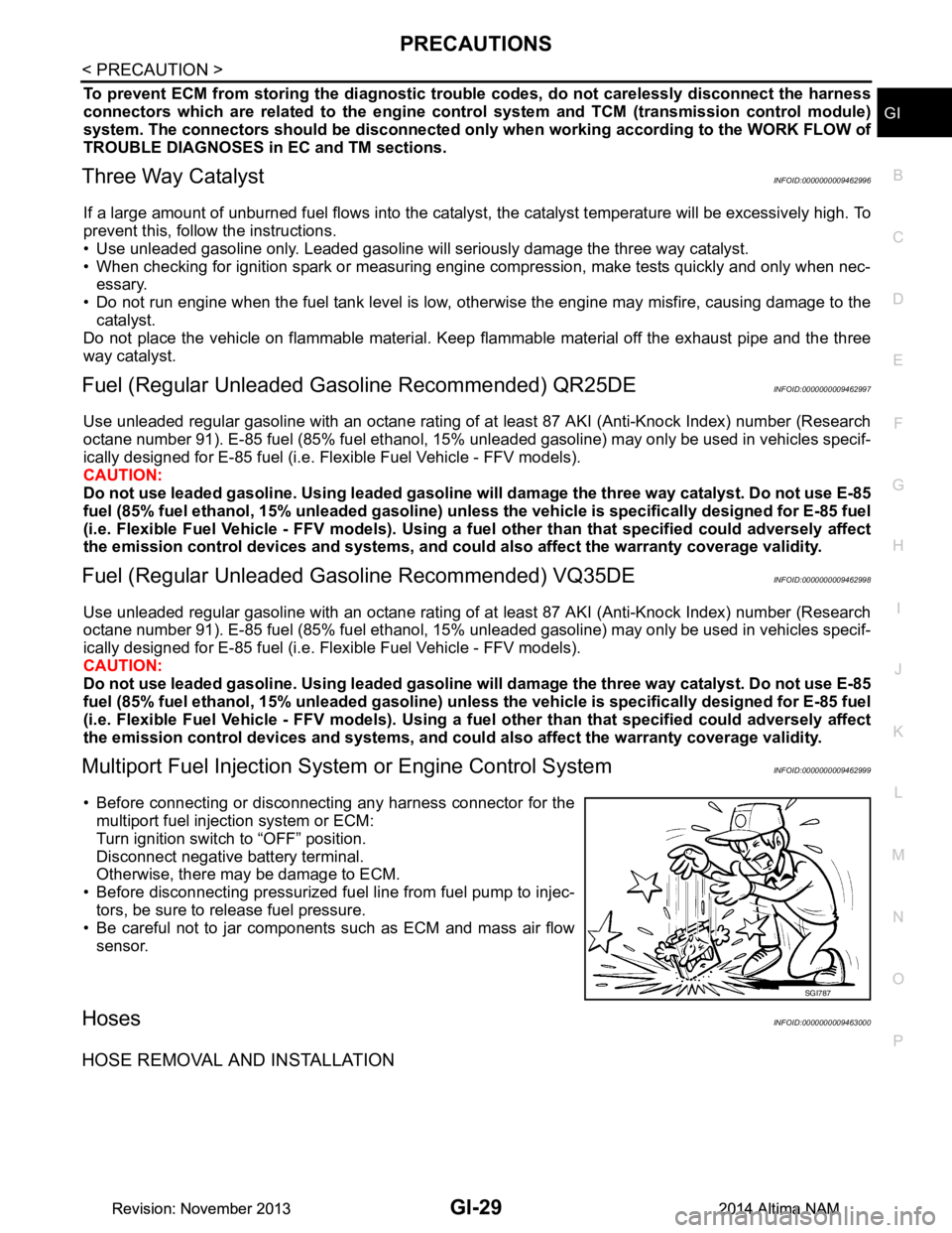
• Before connecting or disconnecti ng any harness connector for the
multiport fuel injection system or ECM:
Turn ignition switch to “OFF” position.
Disconnect negative battery terminal.
Otherwise, there may be damage to ECM.
• Before disconnecting pressurized fuel line from fuel pump to injec-
tors, be sure to release fuel pressure.
• Be careful not to jar components such as ECM and mass air flow sensor.
HosesINFOID:0000000009463000
HOSE REMOVAL AND INSTALLATION
SGI787
Revision: November 20132014 Altima NAMRevision: November 20132014 Altima NAM
Page 2567 of 4801
SERVICE INFORMATION FOR ELECTRICAL INCIDENTGI-39
< BASIC INSPECTION >
C
D E
F
G H
I
J
K L
M B
GI
N
O PBASIC INSPECTION
SERVICE INFORMATION FO R ELECTRICAL INCIDENT
Work FlowINFOID:0000000009463011
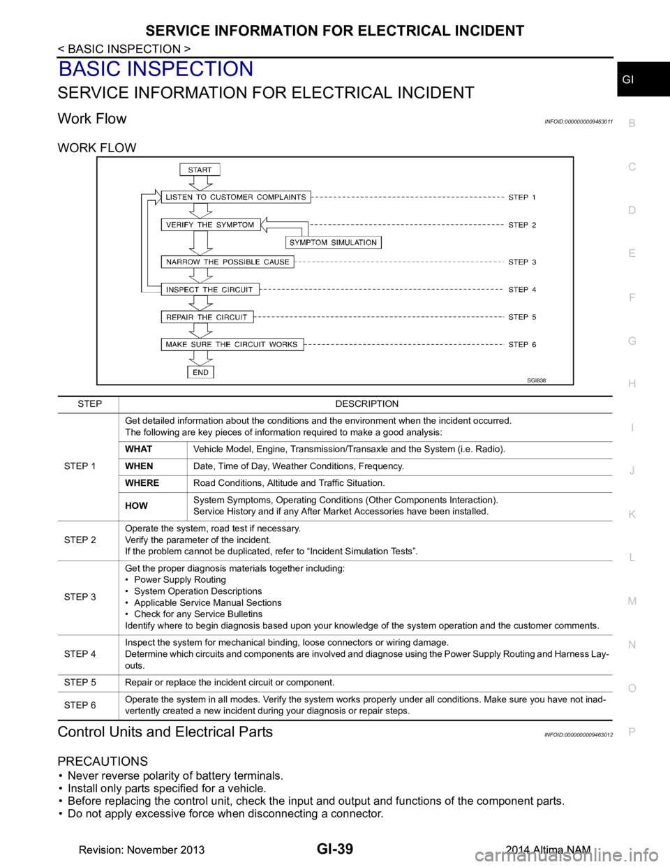
WORK FLOW
Control Units and Electrical PartsINFOID:0000000009463012
PRECAUTIONS
• Never reverse polarity of battery terminals.
• Install only parts specified for a vehicle.
• Before replacing the control unit, check the i nput and output and functions of the component parts.
• Do not apply excessive force when disconnecting a connector.
SGI838
STEP DESCRIPTION
STEP 1 Get detailed information about the conditions and the environment when the incident occurred.
The following are key pieces of information required to make a good analysis:
WHAT Vehicle Model, Engine, Transmission/Transaxle and the System (i.e. Radio).
WHEN Date, Time of Day, Weather Conditions, Frequency.
WHERE Road Conditions, Altitude and Traffic Situation.
HOW System Symptoms, Operating Conditions (Other Components Interaction).
Service History and if any After Market Accessories have been installed.
STEP 2 Operate the system, road test if necessary.
Verify the parameter of the incident.
If the problem cannot be duplicated, refer to “Incident Simulation Tests”.
STEP 3 Get the proper diagnosis materials together including:
• Power Supply Routing
• System Operation Descriptions
• Applicable Service Manual Sections
• Check for any Service Bulletins
Identify where to begin diagnosis based upon your knowledge of the system operation and the customer comments.
STEP 4 Inspect the system for mechanical binding, loose connectors or wiring damage.
Determine which circuits and components are involved and diagnose using the Power Supply Routing and Harness Lay-
outs.
STEP 5 Repair or replace the incident circuit or component.
STEP 6 Operate the system in all modes. Verify the system works properly under all conditions. Make sure you have not inad-
vertently created a new incident during your diagnosis or repair steps.
Revision: November 20132014 Altima NAMRevision: November 20132014 Altima NAM
Page 2572 of 4801
GI-44
< BASIC INSPECTION >
SERVICE INFORMATION FOR ELECTRICAL INCIDENT
lowing section illustrates ways to simulate the conditions/environment under which the owner experiences an
electrical incident.
The section is broken into the six following topics:• Vehicle vibration
• Heat sensitive
• Freezing
• Water intrusion
• Electrical load
• Cold or hot start up
Get a thorough description of the incident from the customer . It is important for simulating the conditions of the
problem.
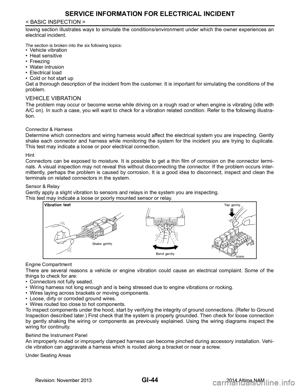
VEHICLE VIBRATION
The problem may occur or become worse while driving on a rough road or when engine is vibrating (idle with
A/C on). In such a case, you will want to check for a vi bration related condition. Refer to the following illustra-
tion.
Connector & Harness
Determine which connectors and wiring harness would affect the electrical system you are inspecting. Gently
shake each connector and harness while monitoring the sy stem for the incident you are trying to duplicate.
This test may indicate a loose or poor electrical connection.
Hint
Connectors can be exposed to moisture. It is possible to get a thin film of corrosion on the connector termi-
nals. A visual inspection may not reveal this without disconnecting the connector. If the problem occurs inter-
mittently, perhaps the problem is caused by corrosion. It is a good idea to disconnect, inspect and clean the
terminals on related connectors in the system.
Sensor & Relay
Gently apply a slight vibration to sensors and relays in the system you are inspecting.
This test may indicate a loose or poorly mounted sensor or relay.
Engine Compartment
There are several reasons a vehicle or engine vibration could cause an electrical complaint. Some of the
things to check for are:
• Connectors not fully seated.
• Wiring harness not long enough and is being stressed due to engine vibrations or rocking.
• Wires laying across brackets or moving components.
• Loose, dirty or corroded ground wires.
• Wires routed too close to hot components.
To inspect components under the hood, start by verifyi ng the integrity of ground connections. (Refer to Ground
Inspection described later.) First check that the system is properly grounded. Then check for loose connection
by gently shaking the wiring or components as previous ly explained. Using the wiring diagrams inspect the
wiring for continuity.
Behind the Instrument Panel
An improperly routed or improperly clamped harness can become pinched during accessory installation. Vehi-
cle vibration can aggravate a harness which is routed along a bracket or near a screw.
Under Seating Areas
SGI839
Revision: November 20132014 Altima NAMRevision: November 20132014 Altima NAM
Page 2579 of 4801
CONSULT CHECKING SYSTEMGI-51
< BASIC INSPECTION >
C
D E
F
G H
I
J
K L
M B
GI
N
O PCONSULT CHECKING SYSTEM
DescriptionINFOID:0000000009463016
CAUTION:
After disconnecting the CONSULT vehicle interface (VI) from the data link connector, the ignition must
be cycled OFF → ON (for at least 5 seconds) → OFF. If this step is not performed, the BCM may not go
to “sleep mode”, potentiall y causing a discharged battery and a no-start condition.
NOTE:
This vehicle is diagnosed using the CONSULT-III plus.
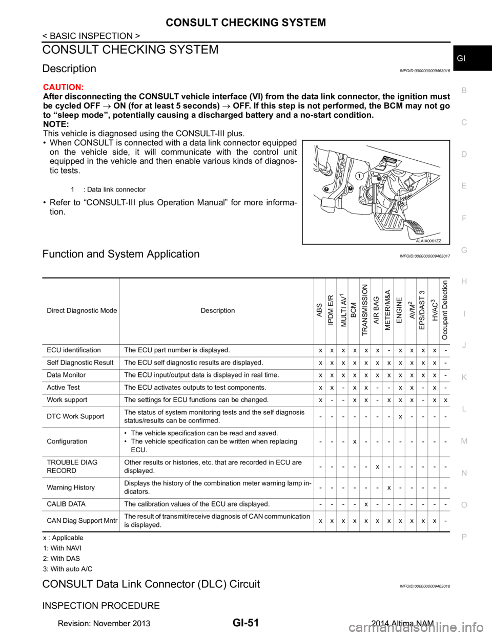
• When CONSULT is connected with a data link connector equipped on the vehicle side, it will communicate with the control unit
equipped in the vehicle and then enable various kinds of diagnos-
tic tests.
• Refer to “CONSULT-III plus Operation Manual” for more informa- tion.
Function and System ApplicationINFOID:0000000009463017
x : Applicable
1: With NAVI
2: With DAS
3: With auto A/C
CONSULT Data Link Connector (DLC) CircuitINFOID:0000000009463018
INSPECTION PROCEDURE
1 : Data link connector
ALAIA0061ZZ
Direct Diagnostic Mode DescriptionABS
IPDM E/R
MULTI AV
1
BCM
TRANSMISSION
AIR BAG
METER/M&A
ENGINE
AV M
2
EPS/DAST 3 HVAC
3
Occupant Detection
ECU identification The ECU part number is displayed. x x x x x x - x x x x -
Self Diagnostic Result The ECU self diagnostic results are displayed. x x x x x x x x x x x -
Data Monitor The ECU input/output data is displayed in real time. x x x x x x x x x x x -
Active Test The ECU activates outputs to test components. x x - x x - - x x - x -
Work support The settings for ECU functions can be changed. x - - x x - x x x - x x
DTC Work Support The status of system monitoring tests and the self diagnosis
status/results can be confirmed. -------x----
Configuration • The vehicle specification can be read and saved.
• The vehicle specification can be written when replacing ECU. ---x--------
TROUBLE DIAG
RECORD Other results or histories, etc. that are recorded in ECU are
displayed. -----x------
Warning History Displays the history of the combination meter warning lamp in-
dicators. ------x-----
CALIB DATA The calibration values of the ECU are displayed. - - - - x - - - - - - -
CAN Diag Support Mntr The result of transmit/receive diagnosis of CAN communication
is displayed. xxxxxxxxxxx-
Revision: November 20132014 Altima NAMRevision: November 20132014 Altima NAM
Page 2586 of 4801
GW-6
< SYMPTOM DIAGNOSIS >
SQUEAK AND RATTLE TROUBLE DIAGNOSES
If possible, drive the vehicle with the customer until the noise is duplicated. Note any additional information on
the Diagnostic Worksheet regarding the conditions or lo cation of the noise. This information can be used to
duplicate the same conditions when you confirm the repair.
If the noise can be duplicated easily during the test drive, to help identify the source of the noise, try to dupli-
cate the noise with the vehicle stopped by doing one or all of the following:
1) Close a door.
2) Tap or push/pull around the area where the noise appears to be coming from.
3) Rev the engine.
4) Use a floor jack to recreate vehicle “twist”.
5) At idle, apply engine load (electrical load, half-clutch on M/T model, drive position on CVT and A/T models).
6) Raise the vehicle on a hoist and hit a tire with a rubber hammer.
• Drive the vehicle and attempt to duplicate the conditions the customer states exist when the noise occurs.
• If it is difficult to duplicate the noise, drive the v ehicle slowly on an undulating or rough road to stress the
vehicle body.
CHECK RELATED SERVICE BULLETINS
After verifying the customer concern or symptom, chec k ASIST for Technical Service Bulletins (TSBs) related
to that concern or symptom.
If a TSB relates to the symptom, follo w the procedure to repair the noise.
LOCATE THE NOISE AND IDENTIFY THE ROOT CAUSE
1. Narrow down the noise to a general area. To help pi npoint the source of the noise, use a listening tool
(Chassis Ear: J-39570, Engine Ear: J-39565 and mechanic's stethoscope).
2. Narrow down the noise to a more specific area and identify the cause of the noise by:
• removing the components in the area that you suspect the noise is coming from. Do not use too much force when removing clips and fasteners, otherwise clips and fasteners can be
broken or lost during the repair, resulting in the creation of new noise.
• tapping or pushing/pulling the component that you suspect is causing the noise.
Do not tap or push/pull the component with excessive force, otherwise the noise will be eliminated only
temporarily.
• feeling for a vibration with your hand by touching the component(s) that you suspect is (are) causing the
noise.
• placing a piece of paper between components that you suspect are causing the noise.
• looking for loose components and contact marks. Refer to GW-6, "Generic Squeak and Rattle Troubleshooting"
.
REPAIR THE CAUSE
• If the cause is a loose component, tighten the component securely.
• If the cause is insufficient clearance between components:
- separate components by repositioning or loos ening and retightening the component, if possible.
- insulate components with a suitable insulator such as urethane pads, foam blocks, felt cloth tape or urethane
tape. A NISSAN Squeak and Rattle Kit (J-50397) is av ailable through your authorized NISSAN Parts Depart-
ment.
CAUTION:
Do not use excessive force as many components are constructed of plastic and may be damaged.
NOTE:
• Always check with the Parts Department for the latest parts information.
• The materials contained in the NISSAN Squeak and Rattle Kit (J-50397) are listed on the inside cover of the
kit; and can each be ordered separately as needed.
• The following materials not found in the kit can also be used to repair squeaks and rattles.
- SILICONE GREASE: Use instead of UHMW tape that will be visible or does not fit. The silicone grease will
only last a few months.
- SILICONE SPRAY: Use when grease cannot be applied.
- DUCT TAPE: Use to eliminate movement.
CONFIRM THE REPAIR
Confirm that the cause of a noise is repaired by test driving the vehicle. Operate the vehicle under the same
conditions as when the noise originally occurred. Refer to the notes on the Diagnostic Worksheet.
Generic Squeak and Rattle TroubleshootingINFOID:0000000009463658
Refer to Table of Contents for specific component removal and installation information.
Revision: November 20132014 Altima NAM
Page 2609 of 4801
PRECAUTIONSHA-3
< PRECAUTION >
C
D E
F
G H
J
K L
M A
B
HA
N
O P
PRECAUTION
PRECAUTIONS
Precaution for Supplemental Restraint System (SRS) "AIR BAG" and "SEAT BELT
PRE-TENSIONER"
INFOID:0000000009951784
The Supplemental Restraint System such as “A IR BAG” and “SEAT BELT PRE-TENSIONER”, used along
with a front seat belt, helps to reduce the risk or severi ty of injury to the driver and front passenger for certain
types of collision. Information necessary to service t he system safely is included in the SR and SB section of
this Service Manual.
WARNING:
• To avoid rendering the SRS inoper ative, which could increase the risk of personal injury or death in
the event of a collision which would result in air bag inflation, all maintenance must be performed by
an authorized NISSAN/INFINITI dealer.
• Improper maintenance, including in correct removal and installation of the SRS, can lead to personal
injury caused by unintentional act ivation of the system. For removal of Spiral Cable and Air Bag
Module, see the SR section.
• Do not use electrical test equipm ent on any circuit related to the SRS unless instructed to in this
Service Manual. SRS wiring harnesses can be identi fied by yellow and/or orange harnesses or har-
ness connectors.
PRECAUTIONS WHEN USING POWER TOOLS (AIR OR ELECTRIC) AND HAMMERS
WARNING:
• When working near the Airbag Diagnosis Sensor Un it or other Airbag System sensors with the Igni-
tion ON or engine running, DO NOT use air or el ectric power tools or strike near the sensor(s) with a
hammer. Heavy vibration could activate the sensor( s) and deploy the air bag(s), possibly causing
serious injury.
• When using air or electric power tools or hammers , always switch the Ignition OFF, disconnect the
battery and wait at least three mi nutes before performing any service.
Precaution for WorkINFOID:0000000009463909
• When removing or disassembling each component, be ca reful not to damage or deform it. If a component
may be subject to interference, be sure to protect it with a shop cloth.
• When removing (disengaging) components with a screwdriver or similar tool, be sure to wrap the component with a shop cloth or vinyl tape to protect it.
• Protect the removed parts with a shop cloth and prevent them from being dropped.
• Replace a deformed or damaged clip.
• If a part is specified as a non-reusabl e part, always replace it with a new one.
• Be sure to tighten bolts and nuts securely to the specified torque.
• After installation is complete, be sure to check that each part works properly.
• Follow the steps below to clean components:
- Water soluble dirt:
• Dip a soft cloth into lukewarm water, wring the water out of the cloth and wipe the dirty area.
• Then rub with a soft, dry cloth.
-Oily dirt:
• Dip a soft cloth into lukewarm water with mild detergent (concentration: within 2 to 3%) and wipe the dirty area.
• Then dip a cloth into fresh water, wring the water out of the cloth and wipe the detergent off.
• Then rub with a soft, dry cloth.
- Do not use organic solvent such as thinner, benzene, alcohol or gasoline.
- For genuine leather seats, use a genuine leather seat cleaner.
Precaution for Workin g with HFC-134a (R-134a)INFOID:0000000009463910
WARNING:
• CFC-12 (R-12) refrigerant and HFC-134a (R-134a) refr igerant are not compatible. If the refrigerants
are mixed compressor failure is likely to occur. Refer to HA-21, "Leak Test"
. To determine the purity
of HFC-134a (R-134a) in the vehicle and recovery tank, use Refrigerant Recovery/Recycling Recharg-
ing equipment and Refrigerant Identifier.
Revision: November 20132014 Altima NAM
Page 2628 of 4801
HA-22
< PERIODIC MAINTENANCE >
REFRIGERANT
4. Press UV lamp switch (5) and check A/C system for refrigerant leakage. (Where refrigerant leakage
occurs, fluorescent leak detec tion dye appears in green color.)
WARNING:
Do not look directly into UV lamp light source.
NOTE:
• For continuous operating time of UV lamp, follow the manufacturer operating instructions.
• Illuminate piping joints from different angles using UV lamp and check that there is no leakage.
• Use a mirror in area that is difficult to see to check refrigerant leakage.
• Refrigerant leakage from evaporator can be detected by soaking cotton swab or a similar material with
drain hose water and illuminating it using UV lamp.
• Dust, dirt and packing materials adhesive used for condenser, evaporator, and other locations may fluo- resce. Be careful not to misidentify leakage.
5. Repair or replace parts where refrigerant leakage occurs and wipe off fluorescent leak detection dye. NOTE:
Completely wipe off fluorescent leak detection dy e from gaps between parts, screw threads, and others
using a cotton swab or similar materials.
6. Use a UV lamp to check that no fluorescent leak detection dye remains after finishing work.
WARNING:
Do not look directly into UV lamp light source.
NOTE:
• For continuous operating time of UV lamp, follow the manufacturer operating instructions.
• Dust, dirt, and packing materials adhesive used for condenser, evaporator, and other locations may flu-
oresce. Be careful not to misidentify leakage.
CHECK REFRIGERANT LEAKAGE USING ELECTRICAL LEAK DETECTOR
WARNING:
Do not check refrigerant leakage while the engine is running.
CAUTION:
Be careful of the following it ems so that inaccurate checks or misidentifications are avoided.
• Do not allow refrigerant vapor, shop chemical vapor s, cigarette smoke or others around the vehicle.
• Always check refrigerant leakage in a low air flow en vironment so that refrigerant may not disperse
when leakage occurs.
1. Stop the engine.
2. Connect recovery/recycling/recharging equipment or manifold gauge set (J-39183-C) to A/C service
valve.
3. Check that A/C refrigerant pressure is 345 kPa (3.52 kg/cm
2, 50 psi) or more when temperature is 16 °C
(61 °F) or more. When pressure is lower than the specif ied value, recycle refrigerant completely and fill
refrigerant to the specified level.
NOTE:
Leakages may not be detected if A/C refrigerant pressure is 345 kPa (3.52 kg/cm
2, 50 psi) or less when
temperature is less than 16 °C (61 °F).
4. Clean area where refrigerant leakage check is performed and check refrigerant leakage along all surfaces of pipe connections and A/C system components us ing electrical leak detector (J-41995) probe.
CAUTION:
• Continue checking when a leakag e is found. Always continue and complete checking along all
pipe connections and A/C system components for additional leakage.
• When a leakage is detected, clean leakage area using compressed air and check again.
• When checking leakage of cooling unit inside, always clean inside of drain hose so that the
probe surface may not be exposed to water or dirt.
NOTE:
• Always check leakage starting from high-pressure side and continue to low-pressure side.
• When checking leakage of cooling unit inside, operate bl ower fan motor for 15 minutes or more at the
maximum fan speed while the engine is stopped, and then in sert electrical leak detector probe into drain
hose and hold for 10 minutes or more.
• When disconnecting shut-off valve that is connected to A/C service valve, always evacuate remaining
refrigerant so that misidentification can be avoided.
5. Repair or replace parts where refrigerant leak age is detected. (Leakage is detected but leakage area is
unknown.)
Revision: November 20132014 Altima NAM
Page 2629 of 4801
REFRIGERANTHA-23
< PERIODIC MAINTENANCE >
C
D E
F
G H
J
K L
M A
B
HA
N
O P
6. Start the engine and set A/C control in the following conditions. • A/C switch ON
• Air flow: VENT (ventilation)
• Intake door position: Recirculation
• Temperature setting: Full cold
• Fan (blower) speed: Maximum speed set
7. Run the engine at approximately 1,500 rpm for 2 minutes or more.
8. Stop the engine. Check again for refrigerant leakage. Go to step 4. WARNING:
Be careful not to get burned when the engine is hot.
NOTE:
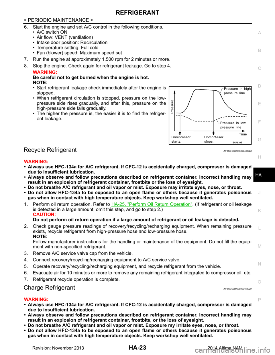
• Start refrigerant leakage check immediately after the engine is stopped.
• When refrigerant circulation is stopped, pressure on the low- pressure side rises gradually, and after this, pressure on the
high-pressure side falls gradually.
• The higher the pressure is, the easier it is to find the refriger-
ant leakage.
Recycle RefrigerantINFOID:0000000009463928
WARNING:
• Always use HFC-134a for A/C refrigerant. If CFC-12 is accidentally charged, compressor is damaged
due to insufficient lubrication.
• Always observe and follow precaution s described on refrigerant container. Incorrect handling may
result in an explosion of refrigerant co ntainer, frostbite or the loss of eyesight.
• Do not breathe A/C refrigerant and oil vapor or mi st. Exposure may irritate eyes, nose, or throat.
• Do not allow HFC-134a to be exposed to an open flame or others because it generates poisonous
gas when in contact with high temperatur e objects. Keep workshop well ventilated.
1. Perform oil return operation. Refer to HA-25, "Perform Oil Return Operation"
. (If refrigerant or oil leakage
is detected in a large amount, omit this step, and go to step 2.)
CAUTION:
Do not perform oil return operation if a large am ount of refrigerant or oil leakage is detected.
2. Check gauge pressure readings of recovery/recyc ling/recharging equipment. When remaining pressure
exists, recycle refrigerant from high-pressure hose and low-pressure hose.
NOTE:
Follow manufacturer instructions for the handling or maintenance of the equipment. Do not fill the equip-
ment with non-specified refrigerant.
3. Remove A/C service valve cap from the vehicle.
4. Connect recovery/recycling/recharging equipment to A/C service valve.
5. Operate recovery/recycling/recharging equipment , and recycle refrigerant from the vehicle.
6. Evacuate air for 10 minutes or more to remove any remaining refrigerant integrated to compressor oil, etc.
7. Refrigerant recycle operation is complete.
Charge RefrigerantINFOID:0000000009463929
WARNING:
• Always use HFC-134a for A/C refrigerant. If CFC-12 is accidentally charged, compressor is damaged
due to insufficient lubrication.
• Always observe and follow precaution s described on refrigerant container. Incorrect handling may
result in an explosion of refrigerant co ntainer, frostbite, or the loss of eyesight.
• Do not breathe A/C refrigerant and oil vapor or mi st. Exposure my irritate eyes, nose, or throat.
• Do not allow HFC-134a to be exposed to an open flame or others because it generates poisonous
gas when in contact with high temperatur e objects. Keep workshop well ventilated.
SHA839E
Revision: November 20132014 Altima NAM