2014 NISSAN TEANA check engine
[x] Cancel search: check enginePage 2284 of 4801

EXL-18
< SYSTEM DESCRIPTION >
DIAGNOSIS SYSTEM (BCM)
HEADLAMP
HEADLAMP : CONSULT Function (BCM - HEADLAMP)INFOID:0000000009956425
CAUTION:
After disconnecting the CONSULT vehicle interface (VI) from the data link connector, the ignition must
be cycled OFF → ON (for at least 5 seconds) → OFF. If this step is not performed, the BCM may not go
to ”sleep mode”, potentially causing a di scharged battery and a no-start condition.
DATA MONITOR
ACTIVE TEST
RAP system RETAINED PWR ×
Signal buffer system SIGNAL BUFFER ×
TPMS AIR PRESSURE MONITOR ××××
System Sub System
Direct Diagnostic Mode
Ecu Identification
Self Diagnostic Result
Data Monitor
Active Test
Work support
Configuration
CAN Diag Support Mntr
Monitor Item [Unit] Description
PUSH SW [On/Off] Indicates condition of push-button ignition switch.
ENGINE STATE [STOP/STALL/CRANK/RUN] Indicates engine st atus received from ECM on CAN communication line.
VEH SPEED 1 [km/h] Indicates vehicle speed signal received from ABS on CAN communication line.
TURN SIGNAL R [On/Off]
Indicates condition of combination switch.
TURN SIGNAL L [On/Off]
TAIL LAMP SW [On/Off]
HI BEAM SW [On/Off]
HEAD LAMP SW 1 [On/Off]
HEAD LAMP SW 2 [On/Off]
PASSING SW [On/Off]
AUTO LIGHT SW [On/Off]
FR FOG SW [On/Off]
DOOR SW-DR [On/Off] Indicates condition of front door switch LH.
DOOR SW-AS [On/Off] Indicates condition of front door switch RH.
DOOR SW-RR [On/Off] Indicates condition of rear door switch RH.
DOOR SW-RL [On/Off] Indicates condition of rear door switch LH.
DOOR SW-BK [On/Off] Indicates condition of trunk switch.
OPTI SEN (DTCT) [V] Indicates outside brightness voltage signal from optical sensor.
OPTI SEN (FILT) [V] Indicates outside brightness voltage signal from optical sensor filtered by BCM.
Test Item Description
FR FOG LAMP This test is able to check front fog lamp operation [On/Off].
DAYTIME RUNNING LIGHT This test is able to check daytime running la mp operation [On/Off].
ILL DIM SIGNAL This test is able to check head lamp illumination dimming operation [On/Off].
Revision: November 20132014 Altima NAMRevision: November 20132014 Altima NAM
Page 2288 of 4801

EXL-22
< SYSTEM DESCRIPTION >
DIAGNOSIS SYSTEM (IPDM E/R)
DIAGNOSIS SYSTEM (IPDM E/R)
Diagnosis DescriptionINFOID:0000000009956487
AUTO ACTIVE TEST
Description
In auto active test mode, the IPDM E/R sends a drive signal to the follo wing systems to check their operation.
• Front wiper (LO, HI)
• Front fog lamps
• Parking lamps
• Side marker lamps
• Tail lamps
• License plate lamps
• Daytime running lamps
• Headlamps (LO, HI)
• A/C compressor
• Cooling fans (LO, HI)
Operation Procedure
CAUTION:
Do not start the engine.
NOTE:
When auto active test is performed with hood opened, sprinkle water on windshield before hand.
NOTE:
• If auto active test mode cannot be actuat ed, check door switch system. Refer to DLK-100,
"Component Function Check".
• When auto active test mode has to be cancelled halfway through test, turn ignition switch OFF.
1. Close the hood and lift the wiper arms from the windshield. (Prevent windshield damage due to wiper
operation)
2. Turn ignition switch OFF.
3. Turn the ignition switch ON, and within 20 seconds, press the front door switch LH 10 times. Then turn the ignition switch OFF.
4. Turn the ignition switch ON within 10 seconds. Af ter that the horn sounds once, and the auto active test
starts.
5. After a series of the following operations is repeated 3 times, auto active test is completed.
Inspection in Auto Active Test Mode
When auto active test mode is actuated, the following operation sequence is repeated 3 times.
*: Outputs duty ratio of 50% for 5 seconds → duty ratio of 100% for 5 seconds on the cooling fan control module.
Operation se-
quence Inspection Location Operation
1 Front wiper LO for 3 seconds → HI for 3 seconds
2 •Front fog lamps
• Parking lamps
• Side marker lamps
•Tail lamps
• License plate lamps 10 seconds
3 Daytime running lamps 10 seconds
4 Headlamps LO ⇔ HI 5 times
5 A/C compressor ON ⇔ OFF 5 times
6
*Cooling fans LO for 5 seconds → HI for 5 seconds
Revision: November 20132014 Altima NAMRevision: November 20132014 Altima NAM
Page 2355 of 4801
POWER SUPPLY AND GROUND CIRCUITEXL-89
< DTC/CIRCUIT DIAGNOSIS >
C
D E
F
G H
I
J
K
M A
B
EXL
N
O P
DTC/CIRCUIT DIAGNOSIS
POWER SUPPLY AND GROUND CIRCUIT
BCM (BODY CONTROL MODULE)
BCM (BODY CONTROL MODULE) : Diagnosis ProcedureINFOID:0000000009956493
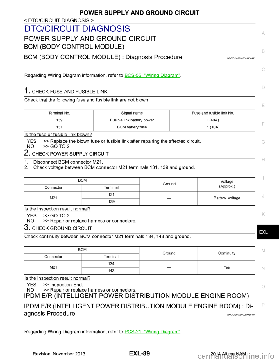
Regarding Wiring Diagram information, refer to BCS-55, "Wiring Diagram".
1. CHECK FUSE AND FUSIBLE LINK
Check that the following fuse and fusible link are not blown.
Is the fuse or fusible link blown?
YES >> Replace the blown fuse or fusible link after repairing the affected circuit.
NO >> GO TO 2
2. CHECK POWER SUPPLY CIRCUIT
1. Disconnect BCM connector M21.
2. Check voltage between BCM connector M21 terminals 131, 139 and ground.
Is the inspection result normal?
YES >> GO TO 3
NO >> Repair or replace harness or connectors.
3. CHECK GROUND CIRCUIT
Check continuity between BCM connector M21 terminals 134, 143 and ground.
Is the inspection result normal?
YES >> Inspection End.
NO >> Repair or replace harness or connectors.
IPDM E/R (INTELLIGENT POWER DIST RIBUTION MODULE ENGINE ROOM)
IPDM E/R (INTELLIGENT POWER DISTRIBUTION MODULE ENGINE ROOM) : Di-
agnosis Procedure
INFOID:0000000009956494
Regarding Wiring Diagram information, refer to PCS-21, "Wiring Diagram".
Terminal No. Signal name Fuse and fusible link No.
139 Fusible link battery power I (40A)
131 BCM battery fuse 1 (10A)
BCM GroundVo l ta g e
(Approx.)
Connector Terminal
M21 131
—Batteryvoltage
139
BCM Ground Continuity
Connector Terminal
M21 134
—Yes
143
Revision: November 20132014 Altima NAMRevision: November 20132014 Altima NAM
Page 2357 of 4801
HEADLAMP (HI) CIRCUITEXL-91
< DTC/CIRCUIT DIAGNOSIS >
C
D E
F
G H
I
J
K
M A
B
EXL
N
O P
HEADLAMP (HI) CIRCUIT
DescriptionINFOID:0000000009463577
The IPDM E/R (intelligent power distribution modul e engine room) controls the headlamp high relay based on
inputs from the BCM over the CAN communication li nes. When the headlamp high relay is energized, power
flows through fuses 34 and 35, located in the IPDM E/R. Power then flows to the front combination lamps to
the headlamp high beam.
Component Function CheckINFOID:0000000009463578
1.CHECK HEADLAMP (HI) OPERATION
WITHOUT CONSULT
1. Start IPDM E/R auto active test. Refer to PCS-8, "Diagnosis Description"
.
2. Check that the headlamp switches to the high beam. NOTE:
HI/LO is repeated 1 second each when using the IPDM E/R auto active test.
CONSULT
1. Select EXTERNAL LAMP of IP DM E/R active test item.
2. While operating the test items, check t hat the headlamp switches to the high beam.
Is the inspection result normal?
YES >> Headlamp (HI) circuit is normal.
NO >> Refer to EXL-91, "Diagnosis Procedure"
.
Diagnosis ProcedureINFOID:0000000009463579
Regarding Wiring Diagram information, refer to EXL-27, "Wiring Diagram - Halogen" or EXL-33, "Wiring Dia-
gram - Xenon".
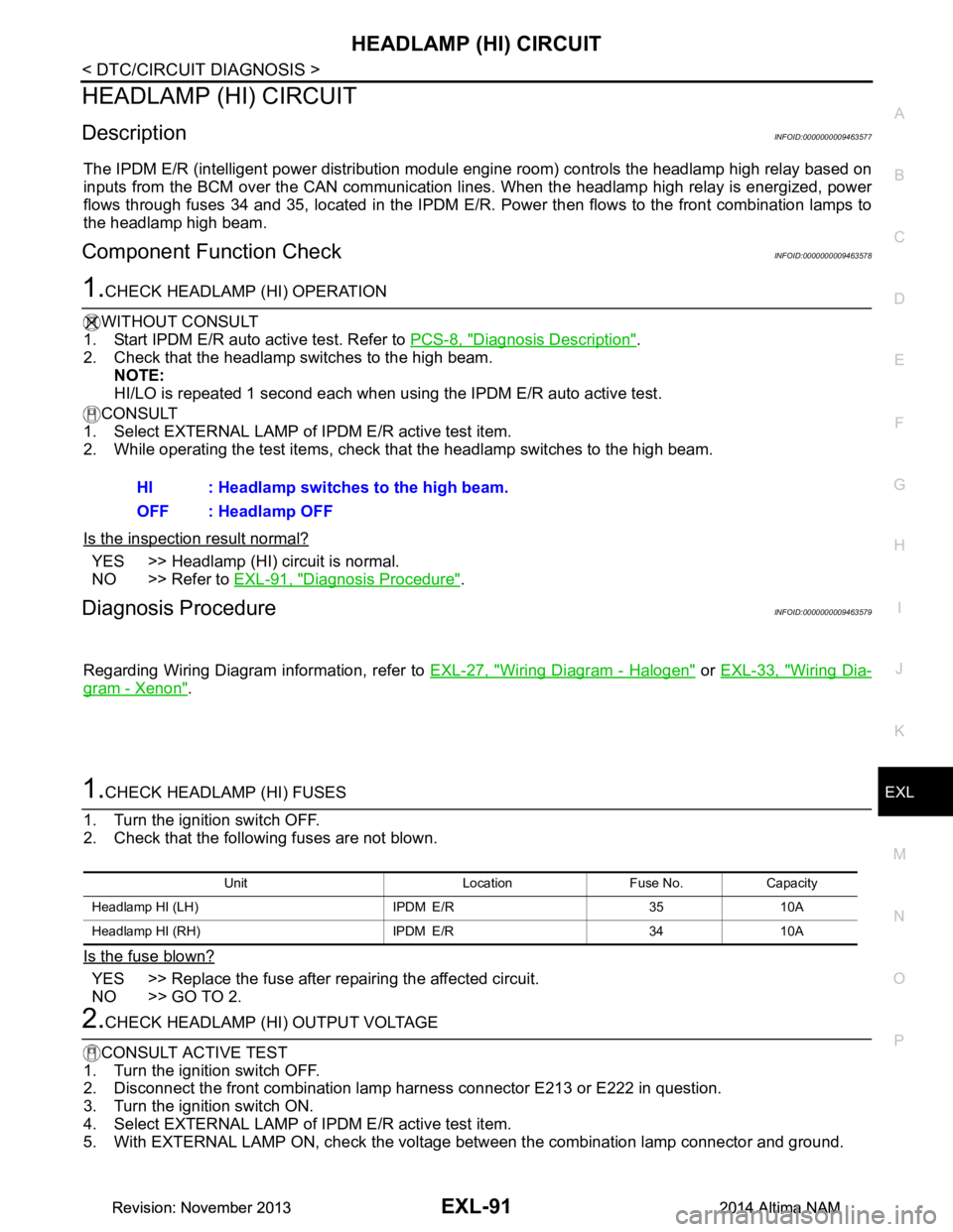
1.CHECK HEADLAMP (HI) FUSES
1. Turn the ignition switch OFF.
2. Check that the following fuses are not blown.
Is the fuse blown?
YES >> Replace the fuse after repairing the affected circuit.
NO >> GO TO 2.
2.CHECK HEADLAMP (HI) OUTPUT VOLTAGE
CONSULT ACTIVE TEST
1. Turn the ignition switch OFF.
2. Disconnect the front combination lamp harness connector E213 or E222 in question.
3. Turn the ignition switch ON.
4. Select EXTERNAL LAMP of IP DM E/R active test item.
5. With EXTERNAL LAMP ON, check the voltage between the combination lamp connector and ground.
HI : Headlamp switches to the high beam.
OFF : Headlamp OFF
Unit Location Fuse No. Capacity
Headlamp HI (LH) IPDM E/R 35 10A
Headlamp HI (RH) IPDM E/R 34 10A
Revision: November 20132014 Altima NAMRevision: November 20132014 Altima NAM
Page 2359 of 4801
HEADLAMP (LO) CIRCUITEXL-93
< DTC/CIRCUIT DIAGNOSIS >
C
D E
F
G H
I
J
K
M A
B
EXL
N
O P
HEADLAMP (LO) CIRCUIT
HEADLAMP (HALOGEN)
HEADLAMP (HALOGEN) : DescriptionINFOID:0000000009463580
The IPDM E/R (intelligent power distribution modul e engine room) controls the headlamp low relay based on
inputs from the BCM over the CAN communication li nes. When the headlamp low relay is energized, power
flows through fuses 36 and 37, located in the IPDM E/R. Power then flows to the front combination lamps to
the headlamp low beam.
HEADLAMP (HALOGEN) : Component Function CheckINFOID:0000000009463581
1.CHECK HEADLAMP (LO) OPERATION
WITHOUT CONSULT
1. Start IPDM E/R auto active test. Refer to PCS-8, "Diagnosis Description"
.
2. Check that the headlamp is turned ON.
NOTE:
HI/LO is repeated 1 second each when using the IPDM E/R auto active test.
CONSULT
1. Select EXTERNAL LAMP of IP DM E/R active test item.
2. While operating the test items, check that the headlamp is turned ON.
Is the inspection result normal?
YES >> Headlamp (LO) is normal.
NO >> Refer to EXL-93, "HEADLAMP (HALOGEN) : Diagnosis Procedure"
.
HEADLAMP (HALOGEN) : Diagnosis ProcedureINFOID:0000000009463582
Regarding Wiring Diagram information, refer to EXL-27, "Wiring Diagram - Halogen".
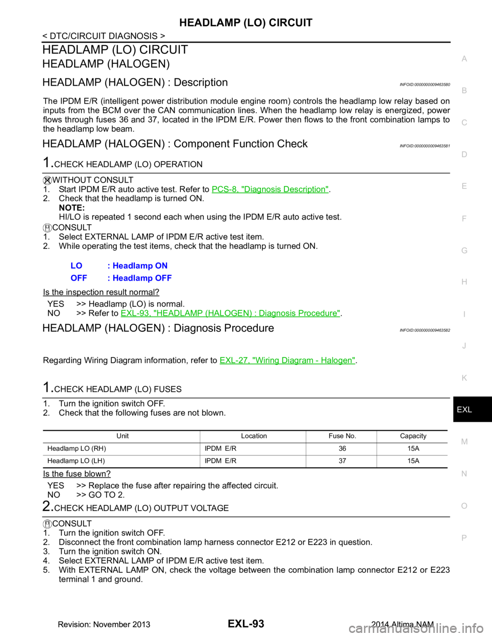
1.CHECK HEADLAMP (LO) FUSES
1. Turn the ignition switch OFF.
2. Check that the following fuses are not blown.
Is the fuse blown?
YES >> Replace the fuse after repairing the affected circuit.
NO >> GO TO 2.
2.CHECK HEADLAMP (LO) OUTPUT VOLTAGE
CONSULT
1. Turn the ignition switch OFF.
2. Disconnect the front combination lamp harness connector E212 or E223 in question.
3. Turn the ignition switch ON.
4. Select EXTERNAL LAMP of IP DM E/R active test item.
5. With EXTERNAL LAMP ON, check the voltage betw een the combination lamp connector E212 or E223
terminal 1 and ground. LO : Headlamp ON
OFF : Headlamp OFF
Unit Location Fuse No. Capacity
Headlamp LO (RH) IPDM E/R 36 15A
Headlamp LO (L H) IPDM E/R 37 15A
Revision: November 20132014 Altima NAMRevision: November 20132014 Altima NAM
Page 2360 of 4801
EXL-94
< DTC/CIRCUIT DIAGNOSIS >
HEADLAMP (LO) CIRCUIT
Is the inspection result normal?
YES >> GO TO 4.
NO >> GO TO 3.
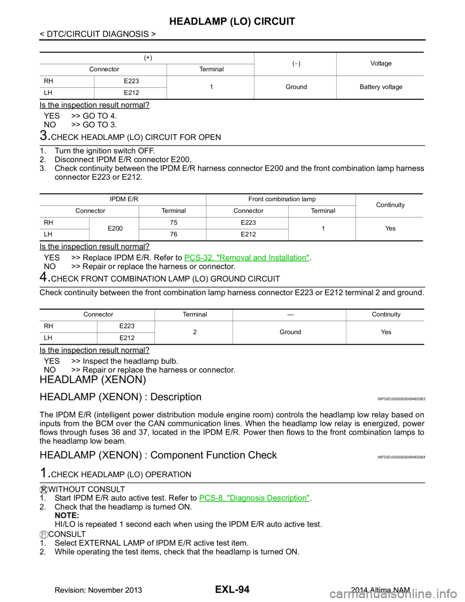
3.CHECK HEADLAMP (LO) CIRCUIT FOR OPEN
1. Turn the ignition switch OFF.
2. Disconnect IPDM E/R connector E200.
3. Check continuity between the IPDM E/R harness c onnector E200 and the front combination lamp harness
connector E223 or E212.
Is the inspection result normal?
YES >> Replace IPDM E/R. Refer to PCS-32, "Removal and Installation".
NO >> Repair or replace the harness or connector.
4.CHECK FRONT COMBINATION LAMP (LO) GROUND CIRCUIT
Check continuity between the front combination la mp harness connector E223 or E212 terminal 2 and ground.
Is the inspection result normal?
YES >> Inspect the headlamp bulb.
NO >> Repair or replace the harness or connector.
HEADLAMP (XENON)
HEADLAMP (XENON) : DescriptionINFOID:0000000009463583
The IPDM E/R (intelligent power distribution modul e engine room) controls the headlamp low relay based on
inputs from the BCM over the CAN communication li nes. When the headlamp low relay is energized, power
flows through fuses 36 and 37, located in the IPDM E/R. Power then flows to the front combination lamps to
the headlamp low beam.
HEADLAMP (XENON) : Component Function CheckINFOID:0000000009463584
1.CHECK HEADLAMP (LO) OPERATION
WITHOUT CONSULT
1. Start IPDM E/R auto active test. Refer to PCS-8, "Diagnosis Description"
.
2. Check that the headlamp is turned ON. NOTE:
HI/LO is repeated 1 second each when usi ng the IPDM E/R auto active test.
CONSULT
1. Select EXTERNAL LAMP of IP DM E/R active test item.
2. While operating the test items, c heck that the headlamp is turned ON.
(+)
(− )Voltage
Connector Terminal
RH E223 1 Ground Battery voltage
LH E212
IPDM E/R Front combination lamp Continuity
Connector Terminal Connector Terminal
RH E20075 E223
1Yes
LH 76 E212
Connector Terminal — Continuity
RH E223 2GroundYes
LH E212
Revision: November 20132014 Altima NAMRevision: November 20132014 Altima NAM
Page 2367 of 4801
FRONT FOG LAMP CIRCUITEXL-101
< DTC/CIRCUIT DIAGNOSIS >
C
D E
F
G H
I
J
K
M A
B
EXL
N
O P
FRONT FOG LAMP CIRCUIT
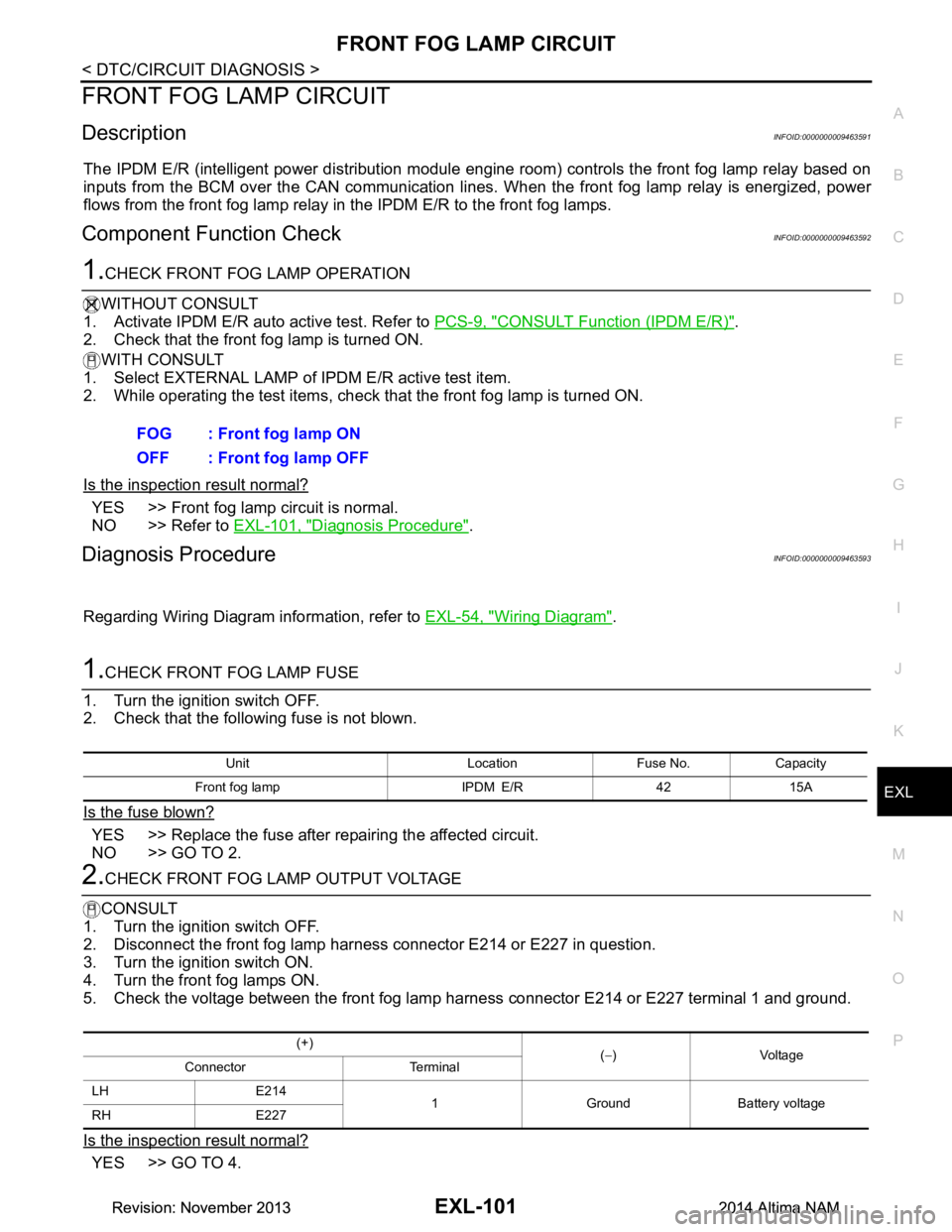
DescriptionINFOID:0000000009463591
The IPDM E/R (intelligent power di stribution module engine room) controls the front fog lamp relay based on
inputs from the BCM over the CAN communication lines . When the front fog lamp relay is energized, power
flows from the front fog lamp relay in the IPDM E/R to the front fog lamps.
Component Function CheckINFOID:0000000009463592
1.CHECK FRONT FOG LAMP OPERATION
WITHOUT CONSULT
1. Activate IPDM E/R auto active test. Refer to PCS-9, "CONSULT Function (IPDM E/R)"
.
2. Check that the front fog lamp is turned ON.
WITH CONSULT
1. Select EXTERNAL LAMP of IP DM E/R active test item.
2. While operating the test items, check that the front fog lamp is turned ON.
Is the inspection result normal?
YES >> Front fog lamp circuit is normal.
NO >> Refer to EXL-101, "Diagnosis Procedure"
.
Diagnosis ProcedureINFOID:0000000009463593
Regarding Wiring Diagram information, refer to EXL-54, "Wiring Diagram".
1.CHECK FRONT FOG LAMP FUSE
1. Turn the ignition switch OFF.
2. Check that the following fuse is not blown.
Is the fuse blown?
YES >> Replace the fuse after repairing the affected circuit.
NO >> GO TO 2.
2.CHECK FRONT FOG LAMP OUTPUT VOLTAGE
CONSULT
1. Turn the ignition switch OFF.
2. Disconnect the front fog lamp harness connector E214 or E227 in question.
3. Turn the ignition switch ON.
4. Turn the front fog lamps ON.
5. Check the voltage between the front fog lamp harness connector E214 or E227 terminal 1 and ground.
Is the inspection result normal?
YES >> GO TO 4. FOG : Front fog lamp ON
OFF : Front fog lamp OFF
Unit Location Fuse No. Capacity
Front fog lamp IPDM E/R 42 15A
(+) (− )Voltage
Connector Terminal
LH E214 1 Ground Battery voltage
RH E227
Revision: November 20132014 Altima NAMRevision: November 20132014 Altima NAM
Page 2384 of 4801
EXL-118
< SYMPTOM DIAGNOSIS >
DAYTIME LIGHT SYSTEM INOPERATIVE
DAYTIME LIGHT SYSTEM INOPERATIVE
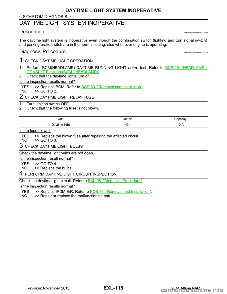
DescriptionINFOID:0000000009463609
The daytime light system is inoperative even though the combination switch (lighting and turn signal switch)
and parking brake switch are in the normal setting, also whenever engine is operating.
Diagnosis ProcedureINFOID:0000000009463610
1.CHECK DAYTIME LIGHT OPERATION
1. Perform BCM(HEADLAMP) DAYTIME RUNNING LIGHT active test. Refer to BCS-19, "HEADLAMP :
CONSULT Function (BCM - HEADLAMP)".
2. Check that the daytime lights turn on.
Is the inspection results normal?
YES >> Replace BCM. Refer to BCS-80, "Removal and Installation".
NO >> GO TO 2.
2.CHECK DAYTIME LIGHT RELAY FUSE
1. Turn ignition switch OFF.
2. Check that the following fuse is not blown.
Is the fuse blown?
YES >> Replace the blown fuse after repairing the affected circuit.
NO >> GO TO 3.
3.CHECK DAYTIME LIGHT BULBS
Check the daytime light bulbs are not open.
Is the inspection result normal?
YES >> GO TO 4.
NO >> Replace the bulbs.
4.PERFORM DAYTIME LIGH T CIRCUIT INSPECTION
Check the daytime light circuit. Refer to EXL-98, "Diagnosis Procedure"
.
Is the inspection results normal?
YES >> Replace IPDM E/R. Refer to PCS-32, "Removal and Installation".
NO >> Repair or replace the malfunctioning part.
Unit Fuse No. Capacity
Daytime light 43 10 A
Revision: November 20132014 Altima NAMRevision: November 20132014 Altima NAM