Page 4136 of 4801
STEERING COLUMNST-33
< REMOVAL AND INSTALLATION >
C
D E
F
H I
J
K L
M A
B
ST
N
O P
STEERING COLUMN
Exploded ViewINFOID:0000000009461270
Removal and InstallationINFOID:0000000009461271
REMOVAL
Hole Cover Seal, Hole Cove r and Lower Shaft Assembly
1. Set wheels to the straight-ahead position.
2. Remove the instrument lower panel LH. Refer to IP-14, "Exploded View"
.
3. Remove lower side bolt (A) of lower shaft assembly (1). • Steering gear (2)
1. Steering column assembly 2. Hole cover 3. Hole cover seal
4. Lower shaft assembly
AWGIA0219ZZ
ALGIA0147ZZ
Revision: November 20132014 Altima NAMRevision: November 20132014 Altima NAM
Page 4137 of 4801

ST-34
< REMOVAL AND INSTALLATION >
STEERING COLUMN
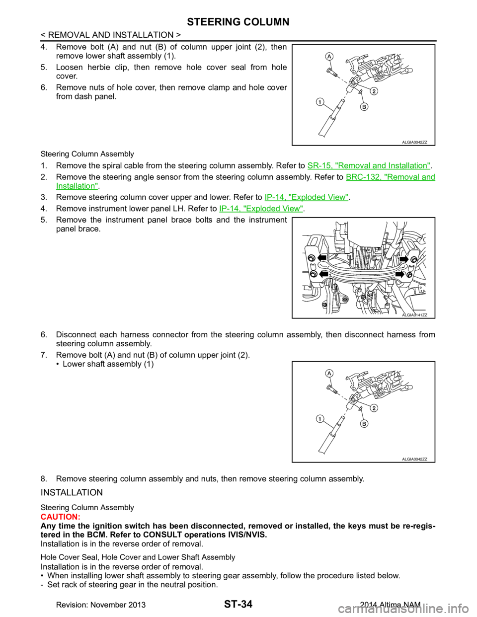
4. Remove bolt (A) and nut (B) of column upper joint (2), thenremove lower shaft assembly (1).
5. Loosen herbie clip, then remove hole cover seal from hole cover.
6. Remove nuts of hole cover, then remove clamp and hole cover from dash panel.
Steering Column Assembly
1. Remove the spiral cable from the steering column assembly. Refer to SR-15, "Removal and Installation".
2. Remove the steering angle sensor from the steering column assembly. Refer to BRC-132, "Removal and
Installation".
3. Remove steering column cover upper and lower. Refer to IP-14, "Exploded View"
.
4. Remove instrument lower panel LH. Refer to IP-14, "Exploded View"
.
5. Remove the instrument panel brace bolts and the instrument panel brace.
6. Disconnect each harness connector from the steeri ng column assembly, then disconnect harness from
steering column assembly.
7. Remove bolt (A) and nut (B) of column upper joint (2). • Lower shaft assembly (1)
8. Remove steering column assembly and nuts, then remove steering column assembly.
INSTALLATION
Steering Column Assembly
CAUTION:
Any time the ignition switch has been disconnected, removed or inst alled, the keys must be re-regis-
tered in the BCM. Refer to CONSULT operations IVIS/NVIS.
Installation is in the reverse order of removal.
Hole Cover Seal, Hole Cove r and Lower Shaft Assembly
Installation is in the reverse order of removal.
• When installing lower shaft assembly to steering gear assembly, follow the procedure listed below.
- Set rack of steering gear in the neutral position.
ALGIA0042ZZ
ALGIA0141ZZ
ALGIA0042ZZ
Revision: November 20132014 Altima NAMRevision: November 20132014 Altima NAM
Page 4635 of 4801

DUCTS AND GRILLESVTL-7
< REMOVAL AND INSTALLATION >
C
D E
F
G H
J
K L
M A
B
VTL
N
O P
DEFROSTER NOZZLE
DEFROSTER NOZZLE : Removal and InstallationINFOID:0000000009461577
REMOVAL
1. Remove the side defroster ducts (LH/RH). Refer to VTL-7, "SIDE DEFROSTER DUCT : Removal and
Installation".
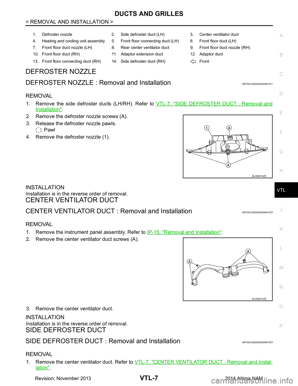
2. Remove the defroster nozzle screws (A).
3. Release the defroster nozzle pawls. : Pawl
4. Remove the defroster nozzle (1).
INSTALLATION
Installation is in the reverse order of removal.
CENTER VENTILATOR DUCT
CENTER VENTILATOR DUCT : Removal and InstallationINFOID:0000000009461578
REMOVAL
1. Remove the instrument panel assembly. Refer to IP-15, "Removal and Installation".
2. Remove the center ventilator duct screws (A).
3. Remove the center ventilator duct.
INSTALLATION
Installation is in the reverse order of removal.
SIDE DEFROSTER DUCT
SIDE DEFROSTER DUCT : Re moval and InstallationINFOID:0000000009461579
REMOVAL
1. Remove the center ventilator duct. Refer to VTL-7, "CENTER VENTILATOR DUCT : Removal and Instal-
lation".
1. Defroster nozzle 2. Side defroster duct (LH) 3. Center ventilator duct
4. Heating and cooling unit assembly 5. Front floor connecting duct (LH) 6. Front floor duct (LH)
7. Front floor duct nozzle (LH) 8. Rear center ventilator duct 9. Front floor duct nozzle (RH)
10. Front floor duct (RH) 11. Adaptor extension duct 12. Adaptor duct
13. Front floor connecting duct (RH) 14. Side defroster duct (RH) Front
ALIIA0613ZZ
ALIIA0614ZZ
Revision: November 20132014 Altima NAM
Page 4636 of 4801

VTL-8
< REMOVAL AND INSTALLATION >
DUCTS AND GRILLES
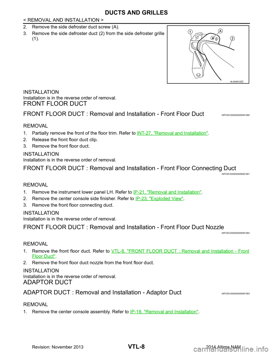
2. Remove the side defroster duct screw (A).
3. Remove the side defroster duct (2) from the side defroster grille
(1).
INSTALLATION
Installation is in the reverse order of removal.
FRONT FLOOR DUCT
FRONT FLOOR DUCT : Removal and In stallation - Front Floor DuctINFOID:0000000009461580
REMOVAL
1. Partially remove the front of the floor trim. Refer to INT-27, "Removal and Installation".
2. Release the front floor duct clip.
3. Remove the front floor duct.
INSTALLATION
Installation is in the reverse order of removal.
FRONT FLOOR DUCT : Removal and Installa tion - Front Floor Connecting Duct
INFOID:0000000009461581
REMOVAL
1. Remove the instrument lower panel LH. Refer to IP-21, "Removal and Installation".
2. Remove the center console side finisher. Refer to IP-23, "Exploded View"
.
3. Remove the front floor connecting duct.
INSTALLATION
Installation is in the reverse order of removal.
FRONT FLOOR DUCT : Removal and Insta llation - Front Floor Duct Nozzle
INFOID:0000000009461582
REMOVAL
1. Remove the front floor duct. Refer to VTL-8, "FRONT FLOOR DUCT : Removal and Installation - Front
Floor Duct".
2. Remove the front floor duct nozzle from the front floor duct.
INSTALLATION
Installation is in the reverse order of removal.
ADAPTOR DUCT
ADAPTOR DUCT : Removal and Installation - Adaptor DuctINFOID:0000000009461583
REMOVAL
1. Remove the center console assembly. Refer to IP-18, "Removal and Installation".
ALIIA0612ZZ
Revision: November 20132014 Altima NAM
Page 4638 of 4801
VTL-10
< REMOVAL AND INSTALLATION >
DUCTS AND GRILLES
Exploded View
INFOID:0000000009461586
FRONT
REAR
CENTER VENTIL AT O R G R I L L E
ALIIA0637ZZ
1. Instrument panel 2. Side defroster grille (LH) 3. Side ventilator grille (LH)
4. Center ventilator grille 5. Cluster lid C 6. Side ventilator grille (RH)
7. Side defroster grille (LH)
ALIIA0638ZZ
1. Center console assembly 2. Rear center ventilator grille
Revision: November 20132014 Altima NAM
Page 4681 of 4801

WT-6
< SYSTEM DESCRIPTION >
COMPONENT PARTS
SYSTEM DESCRIPTION
COMPONENT PARTS
Component Parts LocationINFOID:0000000009464476
Component DescriptionINFOID:0000000009464477
BCMINFOID:0000000009464478
The BCM reads the air pressure signal received by the remote keyless entry receiver. In addition, the BCM
also uses the outside key antennas (driver side, pass enger side and rear bumper) to identify the location of
the transmitters (if equipped with individual tire pressure display).
The BCM has a self-diagnosis function used to detect system malfunctions.
AWEIA0254ZZ
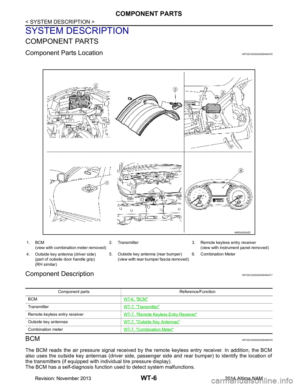
1. BCM
(view with combination meter removed) 2. Transmitter 3. Remote keyless entry receiver
(view with instrument panel removed)
4. Outside key antenna (driver side) (part of outside door handle grip)
(RH similar) 5. Outside key antenna (rear bumper)
(view with rear bumper fascia removed) 6. Combination Meter
Component parts Reference/Function
BCM WT-6, "BCM"
TransmitterWT-7, "Transmitter"
Remote keyless entry receiverWT-7, "Remote Keyless Entry Receiver"
Outside key antennasWT-7, "Outside Key Antennas"
Combination meterWT-7, "Combination Meter"
Revision: November 20132014 Altima NAMRevision: November 20132014 Altima NAM