2014 NISSAN TEANA instrument panel
[x] Cancel search: instrument panelPage 3768 of 4801

SQUEAK AND RATTLE TROUBLE DIAGNOSESSE-19
< SYMPTOM DIAGNOSIS >
C
D E
F
G H
I
K L
M A
B
SE
N
O P
INSTRUMENT PANEL
Most incidents are caused by contact and movement between:
1. Cluster lid A and the instrument panel
2. Acrylic lens and combination meter housing
3. Instrument panel to front pillar finisher
4. Instrument panel to windshield
5. Instrument panel pins
6. Wiring harnesses behind the combination meter
7. A/C defroster duct and duct joint
These incidents can usually be located by tapping or moving the components to duplicate the noise or by
pressing on the components while driving to stop the noi se. Most of these incidents can be repaired by apply-
ing felt cloth tape or silicone spray (in hard to reach areas). Urethane pads can be used to insulate wiring har-
ness.
CAUTION:
Do not use silicone spray to isolate a squeak or ra ttle. If you saturate the area with silicone, you will
not be able to recheck the repair.
CENTER CONSOLE
Components to pay attention to include:
1. Shift selector assembly cover to finisher
2. A/C control unit and cluster lid C
3. Wiring harnesses behind audio and A/C control unit
The instrument panel repair and isolation pr ocedures also apply to the center console.
DOORS
Pay attention to the:
1. Finisher and inner panel making a slapping noise
2. Inside handle escutcheon to door finisher
3. Wiring harnesses tapping
4. Door striker out of alignment causing a popping noise on starts and stops
Tapping or moving the components or pressing on them wh ile driving to duplicate the conditions can isolate
many of these incidents. You can usually insulate the ar eas with felt cloth tape or insulator foam blocks from
the NISSAN Squeak and Rattle Kit (J-50397) to repair the noise.
TRUNK
Trunk noises are often caused by a loose jack or loose items put into the trunk by the owner.
In addition look for:
1. Trunk lid bumpers out of adjustment
2. Trunk lid striker out of adjustment
3. The trunk lid torsion bars knocking together
4. A loose license plate or bracket
Most of these incidents can be repaired by adjusting, se curing or insulating the item(s) or component(s) caus-
ing the noise.
SUNROOF/HEADLINING
Noises in the sunroof/headlining area can often be traced to one of the following:
1. Sunroof lid, rail, linkage or seals making a rattle or light knocking noise
2. Sun visor shaft shaking in the holder
3. Front or rear windshield touching headlining and squeaking
Again, pressing on the components to stop the noise while duplicating the conditions can isolate most of these
incidents. Repairs usually consist of insulating with felt cloth tape.
OVERHEAD CONSOLE (FRONT AND REAR)
Overhead console noises are often caused by the cons ole panel clips not being engaged correctly. Most of
these incidents are repaired by pushing up on the c onsole at the clip locations until the clips engage.
In addition look for:
Revision: November 20132014 Altima NAMRevision: November 20132014 Altima NAM
Page 3837 of 4801

SEC-12
< SYSTEM DESCRIPTION >
SYSTEM
NOTE:
Refer to DLK-23, "INTELLIGENT KEY SYSTEM : System Description"
for any functions other than engine
start function of Intelligent Key system.
PRECAUTIONS FOR INTELLIGENT KEY SYSTEM
The transponder [the chip for NVIS (NATS) ID verifi cation] is integrated into the Intelligent Key.
In that case, the NVIS (NATS) ID verification can be performed when Intelligent Key backside is con-
tacted to push-button ignition switch. If verification result is OK, engine can be started.
OPERATION WHEN INTELLIGENT KEY IS CARRIED
1. When the push-button ignition switch is pressed, the BCM activates the inside key antenna and transmits
the request signal to the Intelligent Key.
2. The Intelligent Key receives the request signal and transmits the Intelligent Key ID signal to the BCM.
3. BCM receives the Intelligent Key ID signal via remote keyless entry receiver and verifies it with the regis-
tered ID.
4. BCM turns ACC relay ON and transmits the ignition power supply ON signal to IPDM E/R.
5. IPDM E/R turns the ignition relay ON and starts the ignition power supply.
6. BCM detects that the selector leve r position and brake pedal operating condition.
7. BCM transmits the starter request signal to IPDM E/R and turns the starter relay in IPDM E/R ON if BCM judges that the engine start condition* is satisfied.
8. IPDM E/R turns the starter control relay ON when receiving the starter request signal.
9. Power supply is supplied through the starter relay and the starter control relay to operate the starter motor. CAUTION:
If a malfunction is detected in the Intelligent Key system, the “KEY” warning lamp in the combina-
tion meter illuminates. At that ti me, the engine cannot be started.
10. When BCM receives feedback signal from ECM indicati ng that the engine is started, the BCM transmits a
stop signal to IPDM E/R and stops cranking by turning OFF the starter motor relay. (If engine start is
unsuccessful, cranking stops autom atically within 5 seconds.)
CAUTION:
When the Intelligent Key is carri ed outside of the vehicle (inside key antenna detection area) while
the power supply is in the ACC or ON position, even if the engine start condition* is satisfied, the
engine cannot be started.
*: For the engine start condition, refer to the tabl e below “POWER SUPPLY POSITION CHANGE TABLE BY
PUSH-BUTTON IGNITION SWITCH OPERATION”.
OPERATION RANGE
Engine can be started when Intelligent Key is inside the vehicle. However, sometimes engine may not start
when Intelligent Key is on instrument panel or in glove box.
ENGINE START OPERATION WHEN INTELLIGENT KEY IS CONTACTED TO PUSH-BUTTON IG-
NITION SWITCH
When Intelligent Key battery is discharged, the NVIS (NATS) ID verification between transponder in Intelligent
Key and BCM is performed when Intelligent Key backside is contacted to push-button ignition switch. If the
verification result is OK, engine can be started.
POWER SUPPLY POSITION CHANGE TABLE BY PUSH-BUTTON IGNITION SWITCH OPERA-
TION
The power supply position changing operation c an be performed with the following operations.
NOTE:
• When an Intelligent Key is within the detection area of inside key antenna and when Intelligent Key backside
is contacted to push-button ignition switch, it is equivalent to the operations below.
• When starting the engine, the BCM monitors under the engine start conditions:
- Brake pedal operating condition
- Selector lever position
- Vehicle speed
Vehicle speed: less than 4 km/h (2.5 MPH)
Revision: November 20132014 Altima NAMRevision: November 20132014 Altima NAM
Page 3964 of 4801

SR-2
< PRECAUTION >
PRECAUTIONS
PRECAUTION
PRECAUTIONS
Precaution for Supplemental Restraint System (SRS) "AIR BAG" and "SEAT BELT
PRE-TENSIONER"
INFOID:0000000009951759
The Supplemental Restraint System such as “A IR BAG” and “SEAT BELT PRE-TENSIONER”, used along
with a front seat belt, helps to reduce the risk or severi ty of injury to the driver and front passenger for certain
types of collision. Information necessary to service the system safely is included in the SR and SB section of
this Service Manual.
WARNING:
• To avoid rendering the SRS inopera tive, which could increase the risk of personal injury or death in
the event of a collision which would result in air bag inflation, all maintenance must be performed by
an authorized NISS AN/INFINITI dealer.
• Improper maintenance, including in correct removal and installation of the SRS, can lead to personal
injury caused by unintent ional activation of the system. For re moval of Spiral Cable and Air Bag
Module, see the SR section.
• Do not use electrical test equipmen t on any circuit related to the SRS unless instructed to in this
Service Manual. SRS wiring harn esses can be identified by yellow and/or orange harnesses or har-
ness connectors.
PRECAUTIONS WHEN USING POWER TOOLS (AIR OR ELECTRIC) AND HAMMERS
WARNING:
• When working near the Airbag Diagnosis Sensor Unit or other Airbag System sensors with the Igni-
tion ON or engine running, DO NOT use air or electri c power tools or strike near the sensor(s) with a
hammer. Heavy vibration could activate the sensor( s) and deploy the air bag(s), possibly causing
serious injury.
• When using air or electric power tools or hammers , always switch the Ignition OFF, disconnect the
battery and wait at least three minutes before performing any service.
ServiceINFOID:0000000009463063
• Do not use electrical test equipment to check SRS ci rcuits unless instructed to in this Service Manual.
• Before servicing the SRS, turn ignition switch OFF, disconnect both battery cables and wait at least three
minutes.
For approximately three minutes after the cables are remo ved, it is still possible for the air bag and seat belt
pre-tensioner to deploy. Therefore, do not work on any SRS connectors or wires until at least three minutes
have passed.
• Diagnosis sensor unit must always be installed with their arrow marks “ ⇐” pointing towards the front of the
vehicle for proper operation. Also chec k diagnosis sensor unit for cracks, deformities or rust before installa-
tion and replace as required.
• The spiral cable must be aligned with the neutral position since its rotations are limited. Do not turn steering
wheel and column after removal of steering gear.
• Handle air bag module carefully. Always place driver and front passenger air bag modules with the pad side facing upward and seat mounted front side air bag m odule standing with the stud bolt side facing down.
• Conduct self-diagnosis to check entire SRS for proper function after replacing any components.
• After air bag inflates, the instrument panel assembly should be replaced if damaged.
• Always replace instrument panel pad following front passenger air bag deployment.
Precaution for WorkINFOID:0000000009463065
• When removing or disassembling each component, be careful not to damage or deform it. If a component may be subject to interference, be sure to protect it with a shop cloth.
• When removing (disengaging) components with a screwdriver or similar tool, be sure to wrap the component with a shop cloth or vinyl tape to protect it.
• Protect the removed parts with a s hop cloth and prevent them from being dropped.
• Replace a deformed or damaged clip.
• If a part is specified as a non-reusable part, always replace it with a new one.
• Be sure to tighten bolts and nuts securely to the specified torque.
• After installation is complete, be sure to check that each part works properly.
Revision: November 20132014 Altima NAM
Page 3968 of 4801

SR-6
< BASIC INSPECTION >
COLLISION DIAGNOSIS
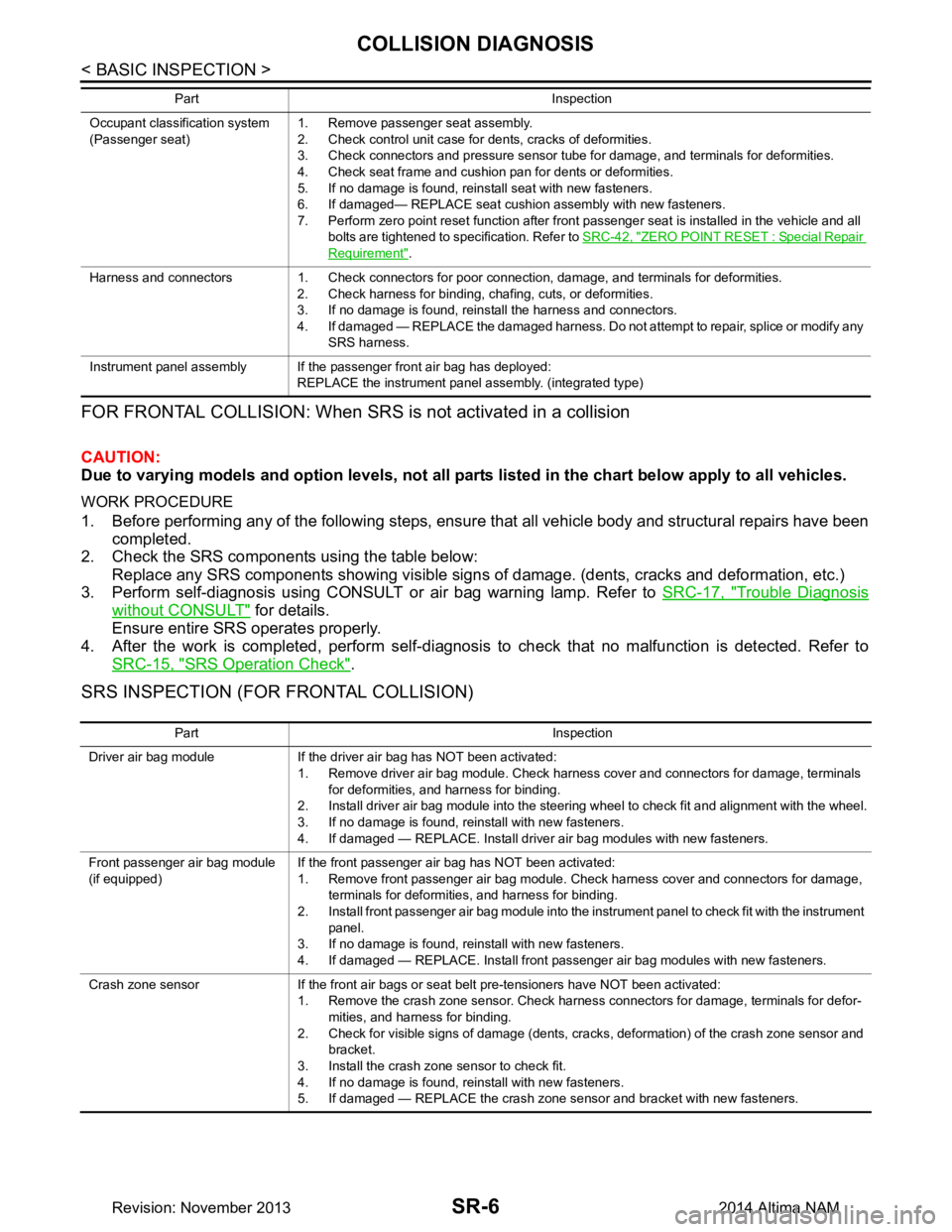
FOR FRONTAL COLLISION: When SRS is not activated in a collision
CAUTION:
Due to varying models and option levels, not all part s listed in the chart below apply to all vehicles.
WORK PROCEDURE
1. Before performing any of the following steps, ensur e that all vehicle body and structural repairs have been
completed.
2. Check the SRS components using the table below:
Replace any SRS components showing visible signs of damage. (dents, cracks and deformation, etc.)
3. Perform self-diagnosis using CONSULT or air bag warning lamp. Refer to SRC-17, "Trouble Diagnosis
without CONSULT" for details.
Ensure entire SRS operates properly.
4. After the work is completed, perform self-diagnosis to check that no malfunction is detected. Refer to
SRC-15, "SRS Operation Check"
.
SRS INSPECTION (FOR FRONTAL COLLISION)
Occupant classification system
(Passenger seat) 1. Remove passenger seat assembly.
2. Check control unit case for dents, cracks of deformities.
3. Check connectors and pressure sensor tube for damage, and terminals for deformities.
4. Check seat frame and cushion pan for dents or deformities.
5. If no damage is found, reinstall seat with new fasteners.
6. If damaged— REPLACE seat cushion assembly with new fasteners.
7. Perform zero point reset function after front passenger seat is installed in the vehicle and all bolts are tightened to specification. Refer to SRC-42, "ZERO POINT RESET : Special Repair
Requirement".
Harness and connectors 1. Check connectors for poor connection, damage, and terminals for deformities. 2. Check harness for binding, chafing, cuts, or deformities.
3. If no damage is found, reinstall the harness and connectors.
4. If damaged — REPLACE the damaged harness. Do not attempt to repair, splice or modify any SRS harness.
Instrument panel assembly If the passenger front air bag has deployed: REPLACE the instrument panel assembly. (integrated type)
Part Inspection
Part Inspection
Driver air bag module If the driver air bag has NOT been activated: 1. Remove driver air bag module. Check harness cover and connectors for damage, terminals for deformities, and harness for binding.
2. Install driver air bag module into the steering wheel to check fit and alignment with the wheel.
3. If no damage is found, reinstall with new fasteners.
4. If damaged — REPLACE. Install driver air bag modules with new fasteners.
Front passenger air bag module
(if equipped) If the front passenger air bag has NOT been activated:
1. Remove front passenger air bag module. Check harness cover and connectors for damage, terminals for deformities, and harness for binding.
2. Install front passenger air bag module into the instrument panel to check fit with the instrument panel.
3. If no damage is found, reinstall with new fasteners.
4. If damaged — REPLACE. Install front passenger air bag modules with new fasteners.
Crash zone sensor If the front air bags or seat belt pre-tensioners have NOT been activated: 1. Remove the crash zone sensor. Check harness connectors for damage, terminals for defor-mities, and harness for binding.
2. Check for visible signs of damage (dents, cracks, deformation) of the crash zone sensor and bracket.
3. Install the crash zone sensor to check fit.
4. If no damage is found, reinstall with new fasteners.
5. If damaged — REPLACE the crash zone sensor and bracket with new fasteners.
Revision: November 20132014 Altima NAM
Page 3969 of 4801

COLLISION DIAGNOSISSR-7
< BASIC INSPECTION >
C
D E
F
G
I
J
K L
M A
B
SR
N
O P
For Side and Rollover CollisionINFOID:0000000009463068
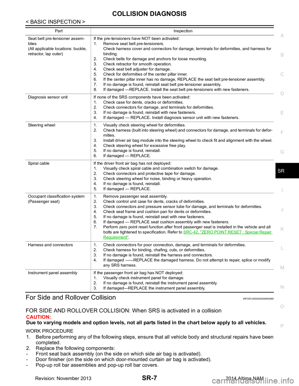
FOR SIDE AND ROLLOVER COLLISION: When SRS is activated in a collision
CAUTION:
Due to varying models and option levels, not all parts listed in the chart below apply to all vehicles.
WORK PROCEDURE
1. Before performing any of the following steps, ensur e that all vehicle body and structural repairs have been
completed.
2. Replace the following components:
- Front seat back assembly (on the side on which side air bag is activated).
- Door finisher (on the side on which door-mounted curtain air bag is activated).
- Pop-up roll bar assemblies and pop-up roll bar covers.
Seat belt pre-tensioner assem-
blies
(All applicable locations: buckle,
retractor, lap outer) If the pre-tensioners have NOT been activated:
1. Remove seat belt pre-tensioners.
Check harness cover and connectors for damage, terminals for deformities, and harness for
binding.
2. Check belts for damage and anchors for loose mounting.
3. Check retractor for smooth operation.
4. Check seat belt adjuster for damage.
5. Check for deformities of the center pillar inner.
6. If the center pillar inner has no damage, REPLACE the seat belt pre-tensioner assembly.
7. If no damage is found, reinstall seat belt pre-tensioner assembly.
8. If damaged —REPLACE. Install the seat belt pre-tensioners with new fasteners.
Diagnosis sensor unit If none of the SRS components have been activated: 1. Check case for dents, cracks or deformities.
2. Check connectors for damage, and terminals for deformities.
3. If no damage is found, reinstall with new fasteners.
4. If damaged — REPLACE. Install diagnosis sensor unit with new fasteners.
Steering wheel 1. Visually check steering wheel for deformities. 2. Check harness (built into steering wheel) and connectors for damage, and terminals for defor-mities.
3. Install driver air bag module into the steering wheel to check fit and alignment with the wheel.
4. Check steering wheel for excessive free play.
5. If no damage is found, reinstall.
6. If damaged — REPLACE.
Spiral cable If the driver front air bag has not deployed: 1. Visually check spiral cable and combination switch for damage.
2. Check connectors and protective tape for damage.
3. Check steering wheel for noise, binding or heavy operation.
4. If no damage is found, reinstall.
5. If damaged — REPLACE.
Occupant classification system
(Passenger seat) 1. Remove passenger seat assembly.
2. Check control unit case for dents, cracks of deformities.
3. Check connectors and pressure sensor tube for damage, and terminals for deformities.
4. Check seat frame and cushion pan for dents or deformities.
5. If no damage is found, reinstall seat with new fasteners.
6. If damaged — REPLACE seat cushion assembly with new fasteners.
7. Perform zero point reset function after front passenger seat is installed in the vehicle and all
bolts are tightened to specification. Refer to SRC-42, "ZERO POINT RESET : Special Repair
Requirement".
Harness and connectors 1. Check connectors for poor connection, damage, and terminals for deformities. 2. Check harness for binding, chafing, cuts, or deformities.
3. If no damage is found, reinstall the harness and connectors.
4. If damaged ——REPLACE the damaged harness. Do not attempt to repair, splice or modify any SRS harness.
Instrument panel assembly If the passenger front air bag has NOT deployed: 1. Visually check instrument panel for damage.
2. If no damage is found, reinstall the instrument panel assembly.
3. If damaged—REPLACE the instrument panel assembly.
Part Inspection
Revision: November 20132014 Altima NAM
Page 3979 of 4801

FRONT PASSENGER AIR BAG MODULESR-17
< REMOVAL AND INSTALLATION >
C
D E
F
G
I
J
K L
M A
B
SR
N
O P
FRONT PASSENGER AIR BAG MODULE
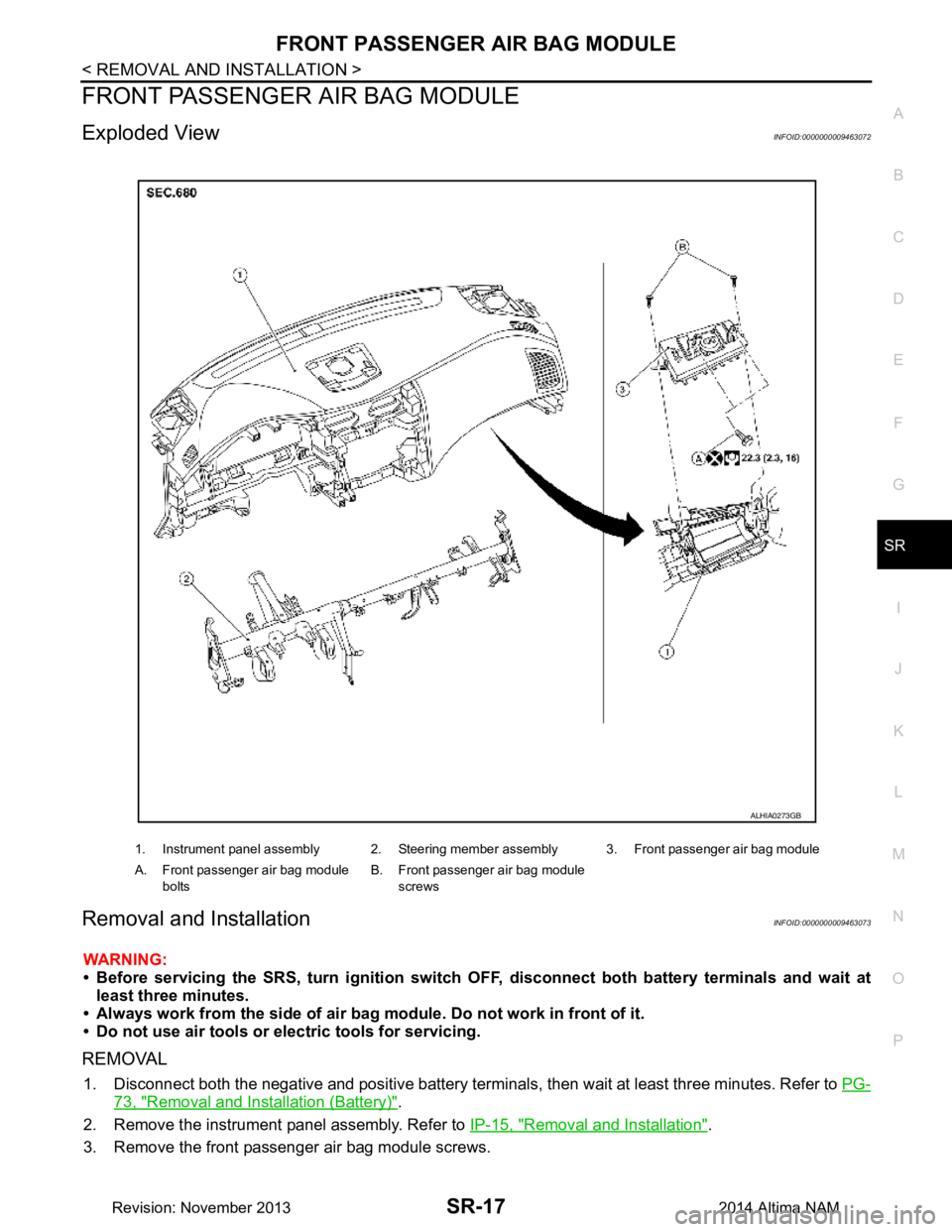
Exploded ViewINFOID:0000000009463072
Removal and InstallationINFOID:0000000009463073
WARNING:
• Before servicing the SRS, turn ignition switch OFF, disconnect both battery terminals and wait at
least three minutes.
• Always work from the side of air bag module. Do not work in front of it.
• Do not use air tools or electric tools for servicing.
REMOVAL
1. Disconnect both the negative and positive battery terminal s, then wait at least three minutes. Refer to PG-
73, "Removal and Installation (Battery)".
2. Remove the instrument panel assembly. Refer to IP-15, "Removal and Installation"
.
3. Remove the front passenger air bag module screws.
1. Instrument panel assembly 2. Steering member assembly 3. Front passenger air bag module
A. Front passenger air bag module bolts B. Front passenger air bag module
screws
ALHIA0273GB
Revision: November 20132014 Altima NAM
Page 3997 of 4801

SRC-4
< PRECAUTION >
PRECAUTIONS
PRECAUTION
PRECAUTIONS
Precaution for Supplemental Restraint System (SRS) "AIR BAG" and "SEAT BELT
PRE-TENSIONER"
INFOID:0000000009460702
The Supplemental Restraint System such as “A IR BAG” and “SEAT BELT PRE-TENSIONER”, used along
with a front seat belt, helps to reduce the risk or severi ty of injury to the driver and front passenger for certain
types of collision. Information necessary to service the system safely is included in the SR and SB section of
this Service Manual.
WARNING:
• To avoid rendering the SRS inopera tive, which could increase the risk of personal injury or death in
the event of a collision which would result in air bag inflation, all maintenance must be performed by
an authorized NISS AN/INFINITI dealer.
• Improper maintenance, including in correct removal and installation of the SRS, can lead to personal
injury caused by unintent ional activation of the system. For re moval of Spiral Cable and Air Bag
Module, see the SR section.
• Do not use electrical test equipmen t on any circuit related to the SRS unless instructed to in this
Service Manual. SRS wiring harn esses can be identified by yellow and/or orange harnesses or har-
ness connectors.
PRECAUTIONS WHEN USING POWER TOOLS (AIR OR ELECTRIC) AND HAMMERS
WARNING:
• When working near the Airbag Diagnosis Sensor Unit or other Airbag System sensors with the Igni-
tion ON or engine running, DO NOT use air or electri c power tools or strike near the sensor(s) with a
hammer. Heavy vibration could activate the sensor( s) and deploy the air bag(s), possibly causing
serious injury.
• When using air or electric power tools or hammers , always switch the Ignition OFF, disconnect the
battery and wait at least three minutes before performing any service.
Precaution for SRS "AIR BAG" and "S EAT BELT PRE-TENSIONER" Service
INFOID:0000000009460703
• Do not use electrical test equipment to check SRS ci rcuits unless instructed to in this Service Manual.
• Before servicing the SRS, turn ignition switch OFF, disconnect both battery cables and wait at least 3 min-
utes.
For approximately 3 minutes after the cables are removed, it is still possible for the air bag and seat belt pre-
tensioner to deploy. Therefore, do not work on any SR S connectors or wires until at least 3 minutes have
passed.
• The air bag diagnosis sensor unit must always be installed with the arrow mark “ ⇐” pointing toward the front
of the vehicle for proper operation. Also check air bag diagnosis sensor unit for cracks, deformities or rust
before installation and replace as required.
• The spiral cable must be aligned with the neutral position since its rotations are limited. Do not attempt to
turn steering wheel or column after removal of steering gear.
• Handle air bag module carefully. Always place driver and front passenger air bag modules with the pad side facing upward and seat mounted front side air bag m odule standing with the stud bolt side facing down.
• Conduct self-diagnosis to check entire SRS for proper function after replacing any components.
• After air bag inflates, the front instrument panel assembly should be replaced if damaged.
Revision: November 20132014 Altima NAMRevision: November 20132014 Altima NAM
Page 4000 of 4801

COMPONENT PARTSSRC-7
< SYSTEM DESCRIPTION >
C
D E
F
G
I
J
K L
M A
B
SRC
N
O P
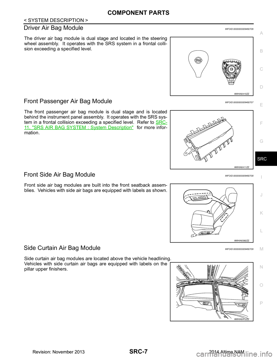
Driver Air Bag ModuleINFOID:0000000009460706
The driver air bag module is dual stage and located in the steering
wheel assembly. It operates with the SRS system in a frontal colli-
sion exceeding a specified level.
Front Passenger Air Bag ModuleINFOID:0000000009460707
The front passenger air bag module is dual stage and is located
behind the instrument panel assembly . It operates with the SRS sys-
tem in a frontal collision exceeding a specified level. Refer to SRC-
11, "SRS AIR BAG SYSTEM : System Description" for more infor-
mation.
Front Side Air Bag ModuleINFOID:0000000009460708
Front side air bag modules are built into the front seatback assem-
blies. Vehicles with side air bags are equipped with labels as shown.
Side Curtain Air Bag ModuleINFOID:0000000009460709
Side curtain air bag modules are located above the vehicle headlining.
Vehicles with side curtain air bags are equipped with labels on the
pillar upper finishers.
AWHIA0410ZZ
AWHIA0411ZZ
AWHIA0382ZZ
AWHIA0412ZZ
Revision: November 20132014 Altima NAMRevision: November 20132014 Altima NAM