2014 NISSAN TEANA battery
[x] Cancel search: batteryPage 2577 of 4801
SERVICE INFORMATION FOR ELECTRICAL INCIDENTGI-49
< BASIC INSPECTION >
C
D E
F
G H
I
J
K L
M B
GI
N
O P
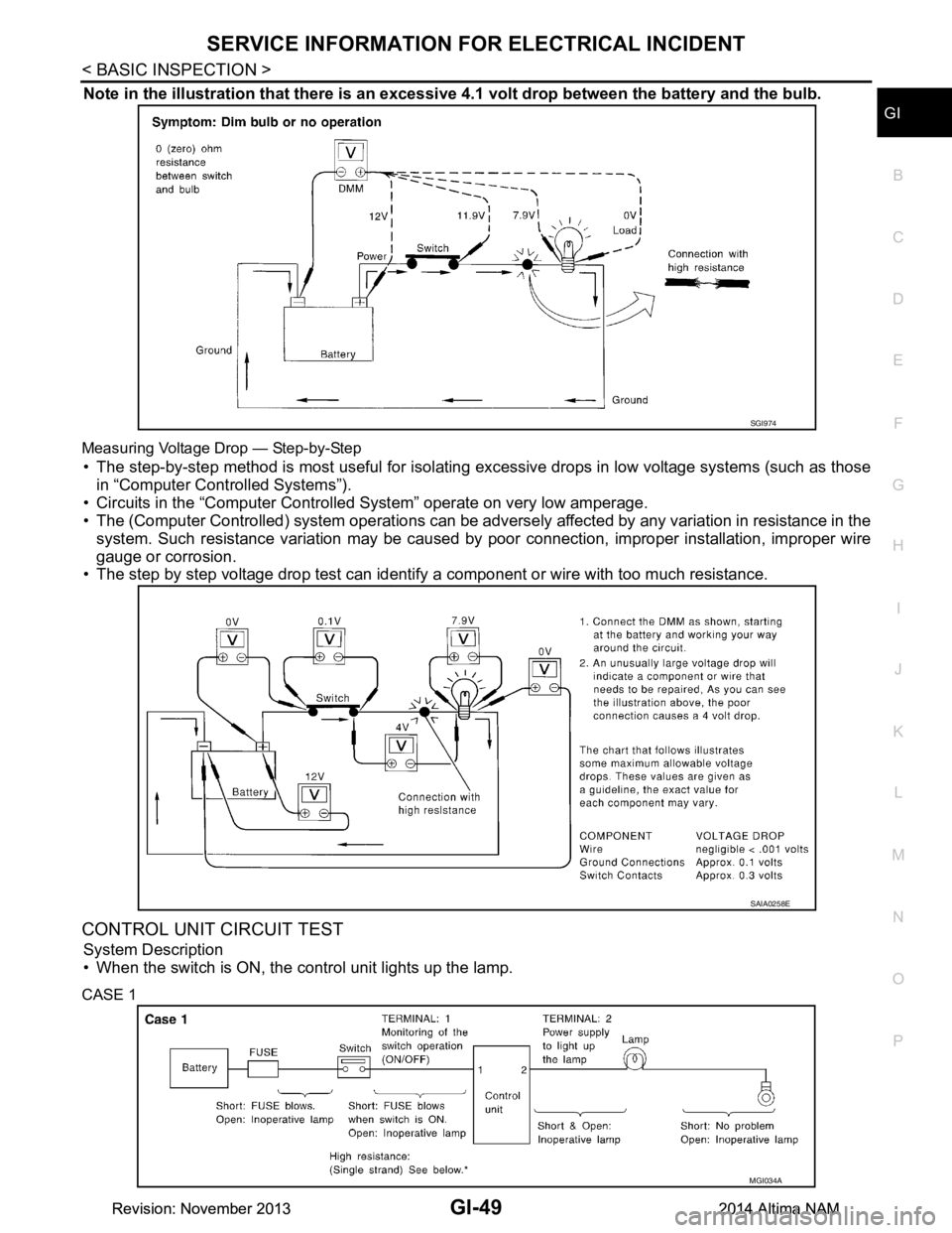
Note in the illustration that there is an excessi ve 4.1 volt drop between the battery and the bulb.
Measuring Voltage Drop — Step-by-Step
• The step-by-step method is most useful for isolating excessive drops in low voltage systems (such as those
in “Computer Controlled Systems”).
• Circuits in the “Computer Controll ed System” operate on very low amperage.
• The (Computer Controlled) system operations can be adversely affected by any variation in resistance in the
system. Such resistance variation may be caused by poor connection, improper installation, improper wire
gauge or corrosion.
• The step by step voltage drop test can identify a component or wire with too much resistance.
CONTROL UNIT CIRCUIT TEST
System Description
• When the switch is ON, the control unit lights up the lamp.
CASE 1
SGI974
SAIA0258E
MGI034A
Revision: November 20132014 Altima NAMRevision: November 20132014 Altima NAM
Page 2578 of 4801
GI-50
< BASIC INSPECTION >
SERVICE INFORMATION FOR ELECTRICAL INCIDENT
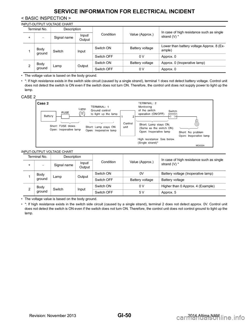
INPUT-OUTPUT VOLTAGE CHART
• The voltage value is based on the body ground.
• *: If high resistance exists in the switch side circuit (caused by a single strand), terminal 1 does not detect battery voltag e. Control unit
does not detect the switch is ON even if the switch does not turn ON. Therefore, the control unit does not supply power to ligh t up the
lamp.
CASE 2
INPUT-OUTPUT VOLTAGE CHART
• The voltage value is based on the body ground.
• *: If high resistance exists in the switch side circuit (caused by a single strand), terminal 2 does not detect approx. 0V. Co ntrol unit
does not detect the switch is ON even if the switch does not turn ON. Therefore, the control unit does not control ground to li ght up the
lamp. Terminal No. Description
Condition Value (Approx.)In case of high resistance such as single
strand (V) *
+ −Signal name Input/
Output
1 Body
ground Switch Input Switch ON Battery voltage
Lower than battery voltage Approx. 8 (Ex-
ample)
Switch OFF 0 V Approx. 0
2 Body
ground Lamp Output Switch ON Battery voltage Approx. 0 (Inoperative lamp)
Switch OFF 0 V Approx. 0
Terminal No. Description Condition Value (Approx.)In case of high resistance such as single
strand (V) *
+ −Signal name Input/
Output
1 Body
ground Lamp Output Switch ON 0V Battery voltage (Inoperative lamp)
Switch OFF Battery voltage Battery voltage
2 Body
ground Switch Input Switch ON 0 V Higher than 0 Approx. 4 (Example)
Switch OFF 5 V Approx. 5
MGI035A
Revision: November 20132014 Altima NAMRevision: November 20132014 Altima NAM
Page 2579 of 4801
CONSULT CHECKING SYSTEMGI-51
< BASIC INSPECTION >
C
D E
F
G H
I
J
K L
M B
GI
N
O PCONSULT CHECKING SYSTEM
DescriptionINFOID:0000000009463016
CAUTION:
After disconnecting the CONSULT vehicle interface (VI) from the data link connector, the ignition must
be cycled OFF → ON (for at least 5 seconds) → OFF. If this step is not performed, the BCM may not go
to “sleep mode”, potentiall y causing a discharged battery and a no-start condition.
NOTE:
This vehicle is diagnosed using the CONSULT-III plus.
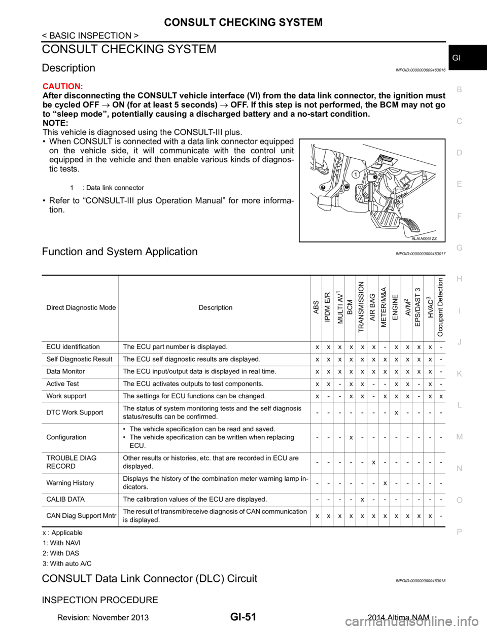
• When CONSULT is connected with a data link connector equipped on the vehicle side, it will communicate with the control unit
equipped in the vehicle and then enable various kinds of diagnos-
tic tests.
• Refer to “CONSULT-III plus Operation Manual” for more informa- tion.
Function and System ApplicationINFOID:0000000009463017
x : Applicable
1: With NAVI
2: With DAS
3: With auto A/C
CONSULT Data Link Connector (DLC) CircuitINFOID:0000000009463018
INSPECTION PROCEDURE
1 : Data link connector
ALAIA0061ZZ
Direct Diagnostic Mode DescriptionABS
IPDM E/R
MULTI AV
1
BCM
TRANSMISSION
AIR BAG
METER/M&A
ENGINE
AV M
2
EPS/DAST 3 HVAC
3
Occupant Detection
ECU identification The ECU part number is displayed. x x x x x x - x x x x -
Self Diagnostic Result The ECU self diagnostic results are displayed. x x x x x x x x x x x -
Data Monitor The ECU input/output data is displayed in real time. x x x x x x x x x x x -
Active Test The ECU activates outputs to test components. x x - x x - - x x - x -
Work support The settings for ECU functions can be changed. x - - x x - x x x - x x
DTC Work Support The status of system monitoring tests and the self diagnosis
status/results can be confirmed. -------x----
Configuration • The vehicle specification can be read and saved.
• The vehicle specification can be written when replacing ECU. ---x--------
TROUBLE DIAG
RECORD Other results or histories, etc. that are recorded in ECU are
displayed. -----x------
Warning History Displays the history of the combination meter warning lamp in-
dicators. ------x-----
CALIB DATA The calibration values of the ECU are displayed. - - - - x - - - - - - -
CAN Diag Support Mntr The result of transmit/receive diagnosis of CAN communication
is displayed. xxxxxxxxxxx-
Revision: November 20132014 Altima NAMRevision: November 20132014 Altima NAM
Page 2582 of 4801
GW-2
< PRECAUTION >
PRECAUTIONS
PRECAUTION
PRECAUTIONS
Precaution for Supplemental Restraint System (SRS) "AIR BAG" and "SEAT BELT
PRE-TENSIONER"
INFOID:0000000009951564
The Supplemental Restraint System such as “A IR BAG” and “SEAT BELT PRE-TENSIONER”, used along
with a front seat belt, helps to reduce the risk or severi ty of injury to the driver and front passenger for certain
types of collision. Information necessary to service the system safely is included in the SR and SB section of
this Service Manual.
WARNING:
• To avoid rendering the SRS inopera tive, which could increase the risk of personal injury or death in
the event of a collision which would result in air bag inflation, all maintenance must be performed by
an authorized NISS AN/INFINITI dealer.
• Improper maintenance, including in correct removal and installation of the SRS, can lead to personal
injury caused by unintent ional activation of the system. For re moval of Spiral Cable and Air Bag
Module, see the SR section.
• Do not use electrical test equipmen t on any circuit related to the SRS unless instructed to in this
Service Manual. SRS wiring harn esses can be identified by yellow and/or orange harnesses or har-
ness connectors.
PRECAUTIONS WHEN USING POWER TOOLS (AIR OR ELECTRIC) AND HAMMERS
WARNING:
• When working near the Airbag Diagnosis Sensor Unit or other Airbag System sensors with the Igni-
tion ON or engine running, DO NOT use air or electri c power tools or strike near the sensor(s) with a
hammer. Heavy vibration could activate the sensor( s) and deploy the air bag(s), possibly causing
serious injury.
• When using air or electric power tools or hammers , always switch the Ignition OFF, disconnect the
battery and wait at least three minutes before performing any service.
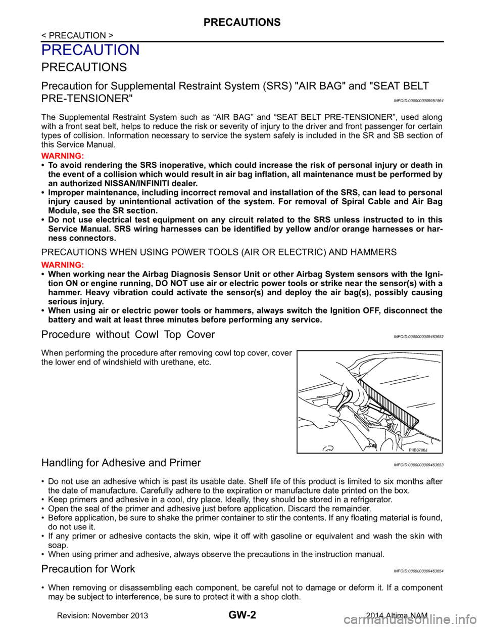
Procedure without Cowl Top CoverINFOID:0000000009463652
When performing the procedure after removing cowl top cover, cover
the lower end of windshield with urethane, etc.
Handling for Adhe sive and PrimerINFOID:0000000009463653
• Do not use an adhesive which is past its usable date. Shel f life of this product is limited to six months after
the date of manufacture. Carefully adhere to the ex piration or manufacture date printed on the box.
• Keep primers and adhesive in a cool, dry place. Ideally, they should be stored in a refrigerator.
• Open the seal of the primer and adhesive just before application. Discard the remainder.
• Before application, be sure to shake the primer container to stir the contents. If any floating material is found,
do not use it.
• If any primer or adhesive contacts the skin, wipe it off with gasoline or equivalent and wash the skin with
soap.
• When using primer and adhesive, always observe the precautions in the instruction manual.
Precaution for WorkINFOID:0000000009463654
• When removing or disassembling each component, be careful not to damage or deform it. If a component
may be subject to interference, be sure to protect it with a shop cloth.
PIIB3706J
Revision: November 20132014 Altima NAM
Page 2594 of 4801
GW-14
< REMOVAL AND INSTALLATION >
FRONT DOOR GLASS
FRONT DOOR GLASS
Removal and InstallationINFOID:0000000009463662
WARNING:
• Before servicing, turn ignition sw itch OFF, disconnect both battery terminals and wait at least three
minutes.
• Do not use air tools or el ectric tools for servicing.
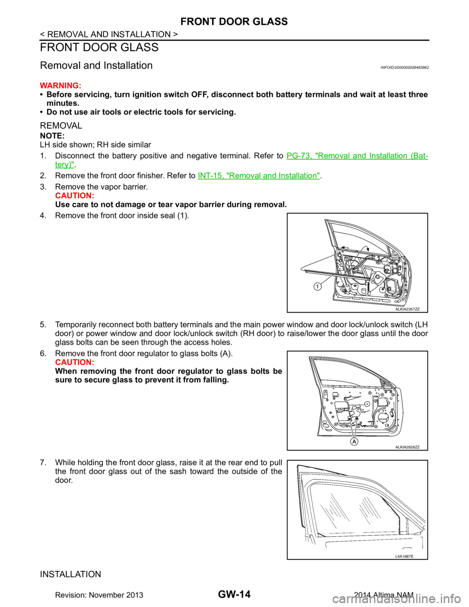
REMOVAL
NOTE:
LH side shown; RH side similar
1. Disconnect the battery positive and negative terminal. Refer to PG-73, "Removal and Installation (Bat-
tery)".
2. Remove the front door finisher. Refer to INT-15, "Removal and Installation"
.
3. Remove the vapor barrier. CAUTION:
Use care to not damage or tear vapor barrier during removal.
4. Remove the front door inside seal (1).
5. Temporarily reconnect both battery terminals and the main power window and door lock/unlock switch (LH door) or power window and door lock/unlock switch ( RH door) to raise/lower the door glass until the door
glass bolts can be seen through the access holes.
6. Remove the front door regul ator to glass bolts (A).
CAUTION:
When removing the front door regulator to glass bolts be
sure to secure glass to prevent it from falling.
7. While holding the front door glass, raise it at the rear end to pull the front door glass out of the sash toward the outside of the
door.
INSTALLATION
ALKIA2357ZZ
ALKIA2628ZZ
LIIA1687E
Revision: November 20132014 Altima NAM
Page 2595 of 4801
FRONT DOOR GLASSGW-15
< REMOVAL AND INSTALLATION >
C
D E
F
G H
I
J
L
M A
B
GW
N
O P
Installation is in the reverse order of removal.
• Tighten the front door regulator to glass bolts to specification.
FRONT DOOR GLASS INSPECTION AFTER INSTALLATION
• Check that the door glass is securely set into the glass run groove.
• Lower the door glass slightly [approximately 10 to 20 mm (0.4 to 0.8 in)] and check that the clearance to the
sash is parallel. If the clearance between the door gla ss and sash is not parallel, loosen the regulator bolts,
guide rail bolts, and door glass and guide rail bolts to correct the glass position.
Inspection and AdjustmentINFOID:0000000009463663
SYSTEM INITIALIZATION (IF NECESSARY)
• If any of the following occur, syst em initialization must be performed.
- Electric power supply to power window switch or motor is interrupted by blown fuse or disconnecting battery cable, etc.
- Removal and installation of the regulator assembly.
- Removal and installation of the motor from the regulator assembly.
- Removal and installation of the harness connector of the power window switch.
- Operation of the regulator assembly as a unit.
- Removal and installation of the door glass.
- Removal and installation of the door glass run.
- Window is partly opened and or closed multiple times with out being fully closed.
• To perform system initialization, refer to the following:
- For LH ONLY ANTI-PINCH, refer to PWC-27, "ADDITIONAL SERVICE WHEN REMOVING BATTERY
NEGATIVE TERMINAL : Special Repair Requirement".
- For LH&RH FRONT ANTI-PINCH, refer to PWC-93, "ADDITIONAL SERVICE WHEN REMOVING BAT-
TERY NEGATIVE TERMINAL : Special Repair Requirement".
INSPECT THE FUNCTION OF THE ANTI-PINCH SYSTEM.
To inspect the anti-pinch system, refer to the following:
• For LH ONLY ANTI-PINCH, refer to PWC-27, "ADDITIONAL SERVICE WHEN REMOVING BATTERY
NEGATIVE TERMINAL : Special Repair Requirement".
• For LH&RH FRONT ANTI-PINCH, refer to PWC-93, "ADDITIONAL SERVICE WHEN REMOVING BAT-
TERY NEGATIVE TERMINAL : Special Repair Requirement".
Front door regulator to glass bol
ts : 6.1 N·m (0.62 kg-m, 54 in-lb)
Revision: November 20132014 Altima NAM
Page 2596 of 4801
GW-16
< REMOVAL AND INSTALLATION >
FRONT REGULATOR
FRONT REGULATOR
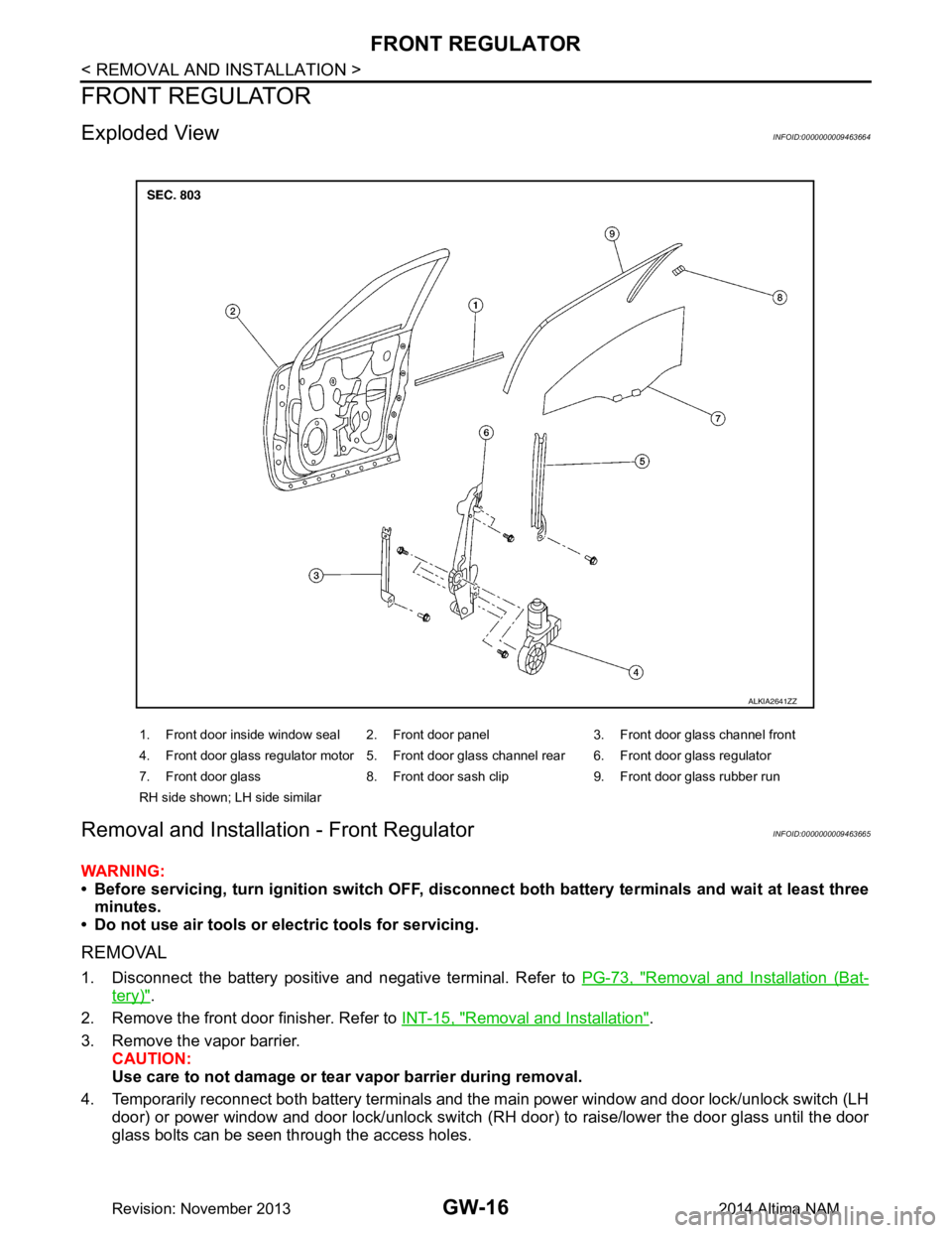
Exploded ViewINFOID:0000000009463664
Removal and Installation - Front RegulatorINFOID:0000000009463665
WARNING:
• Before servicing, turn ignition sw itch OFF, disconnect both battery terminals and wait at least three
minutes.
• Do not use air tools or el ectric tools for servicing.
REMOVAL
1. Disconnect the battery positive and negative terminal. Refer to PG-73, "Removal and Installation (Bat-
tery)".
2. Remove the front door finisher. Refer to INT-15, "Removal and Installation"
.
3. Remove the vapor barrier. CAUTION:
Use care to not damage or tear vapor barrier during removal.
4. Temporarily reconnect both battery terminals and the main power window and door lock/unlock switch (LH door) or power window and door lock/unlock switch ( RH door) to raise/lower the door glass until the door
glass bolts can be seen through the access holes.
1. Front door inside window seal 2. Front door panel 3. Front door glass channel front
4. Front door glass regulator motor 5. Front door glass channel rear 6. Front door glass regulator
7. Front door glass 8. Front door sash clip 9. Front door glass rubber run
RH side shown; LH side similar
ALKIA2641ZZ
Revision: November 20132014 Altima NAM
Page 2598 of 4801
GW-18
< REMOVAL AND INSTALLATION >
FRONT REGULATOR
Inspection and Adjustment
INFOID:0000000009463666
SYSTEM INITIALIZATION (IF NECESSARY)
• If any of the following occur, sy stem initialization must be performed.
- Electric power supply to power window switch or moto r is interrupted by blown fuse or disconnecting battery
cable, etc.
- Removal and installation of the regulator assembly.
- Removal and installation of the motor from the regulator assembly.
- Removal and installation of the harness connector of the power window switch.
- Operation of the regulator assembly as a unit.
- Removal and installation of the door glass.
- Removal and installation of the door glass run.
- Window is partly opened and or closed multiple times with out being fully closed.
• To perform system initialization, refer to the following:
- For LH ONLY ANTI-PINCH, refer to PWC-27, "ADDITIONAL SERVICE WHEN REMOVING BATTERY
NEGATIVE TERMINAL : Special Repair Requirement".
- For LH&RH FRONT ANTI-PINCH, refer to PWC-93, "ADDITIONAL SERVICE WHEN REMOVING BAT-
TERY NEGATIVE TERMINAL : Special Repair Requirement".
INSPECT THE FUNCTION OF THE ANTI-PINCH SYSTEM.
To inspect the anti-pinch system, refer to the following:
• For LH ONLY ANTI-PINCH, refer to PWC-27, "ADDITIONAL SERVICE WHEN REMOVING BATTERY
NEGATIVE TERMINAL : Special Repair Requirement".
• For LH&RH FRONT ANTI-PINCH, refer to PWC-93, "ADDITIONAL SERVICE WHEN REMOVING BAT-
TERY NEGATIVE TERMINAL : Special Repair Requirement".
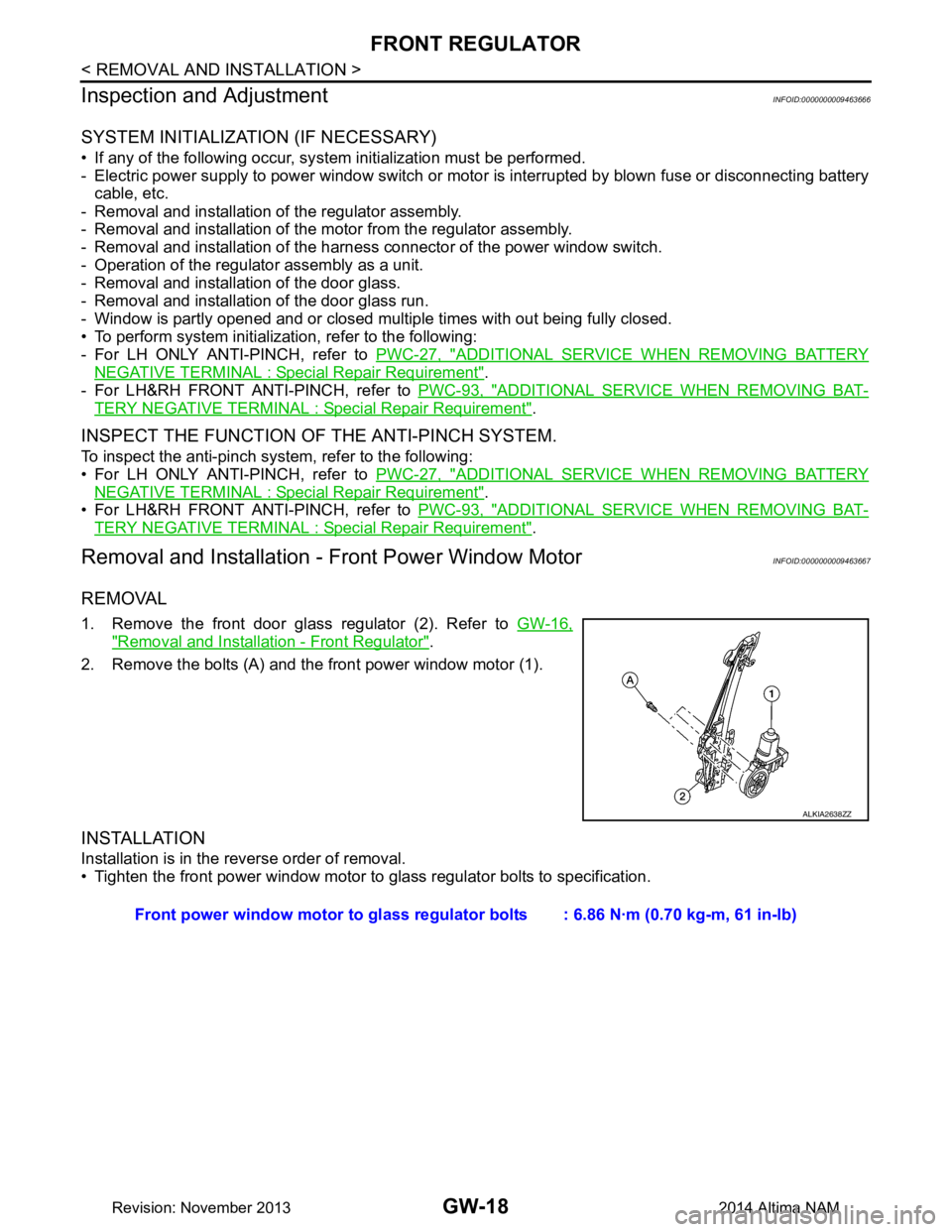
Removal and Installation - Front Power Window MotorINFOID:0000000009463667
REMOVAL
1. Remove the front door glass regulator (2). Refer to GW-16,
"Removal and Installation - Front Regulator".
2. Remove the bolts (A) and the front power window motor (1).
INSTALLATION
Installation is in the reverse order of removal.
• Tighten the front power window motor to glass regulator bolts to specification.
ALKIA2638ZZ
Front power window motor to glass regulator bolts : 6.86 N·m (0.70 kg-m, 61 in-lb)
Revision: November 20132014 Altima NAM