2014 NISSAN TEANA hood open
[x] Cancel search: hood openPage 3842 of 4801

SYSTEMSEC-17
< SYSTEM DESCRIPTION >
C
D E
F
G H
I
J
L
M A
B
SEC
N
O P
• The panic alarm does not start when the theft warning alarm is activating and the panic alarm stops when the theft warning alarm is activated.
The priority of the functions are as per the following.
THEFT WARNING ALARM
• The theft warning alarm function activates horns and headlamps intermittently when BCM detects that any
door or hood is opened by unauthorized means whil e the system is in the ARMED state.
• Security indicator lamp on combination meter always blinks when power supply position is any position other
than ON. Security indicator lamp blinking warns that the vehicle is equipped with a vehicle security system.
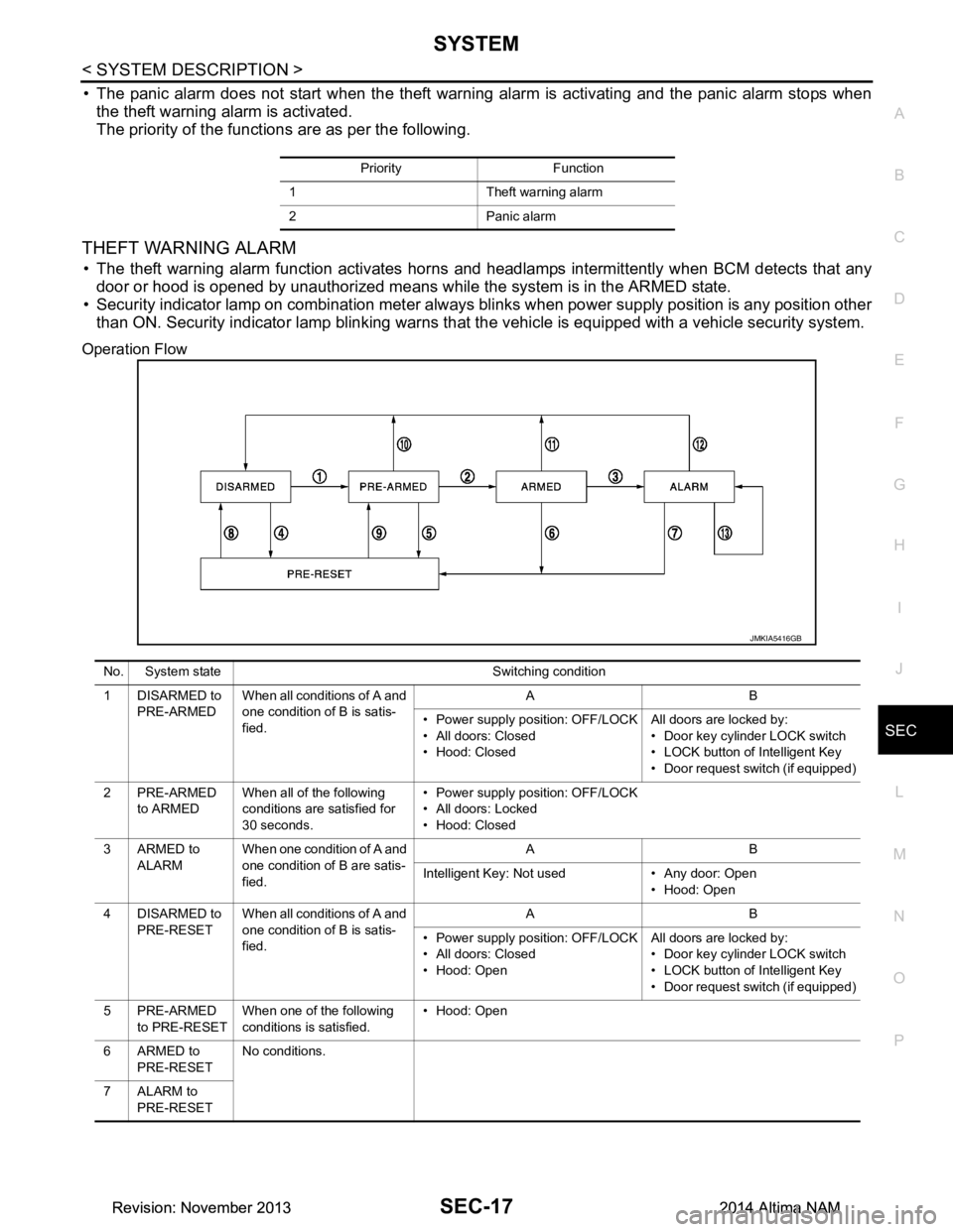
Operation Flow
Priority Function
1 Theft warning alarm
2 Panic alarm
JMKIA5416GB
No. System state Switching condition
1 DISARMED to PRE-ARMED When all conditions of A and
one condition of B is satis-
fied. AB
• Power supply position: OFF/LOCK
• All doors: Closed
• Hood: Closed All doors are locked by:
• Door key cylinder LOCK switch
• LOCK button of Intelligent Key
• Door request switch (if equipped)
2PRE-ARMED to ARMED When all of the following
conditions are satisfied for
30 seconds. • Power supply position: OFF/LOCK
• All doors: Locked
• Hood: Closed
3ARMED to ALARM When one condition of A and
one condition of B are satis-
fied. AB
Intelligent Key: Not used • Any door: Open • Hood: Open
4 DISARMED to PRE-RESET When all conditions of A and
one condition of B is satis-
fied. AB
• Power supply position: OFF/LOCK
• All doors: Closed
• Hood: Open All doors are locked by:
• Door key cylinder LOCK switch
• LOCK button of Intelligent Key
• Door request switch (if equipped)
5PRE-ARMED to PRE-RESET When one of the following
conditions is satisfied. • Hood: Open
6ARMED to PRE-RESET No conditions.
7 ALARM to PRE-RESET
Revision: November 20132014 Altima NAMRevision: November 20132014 Altima NAM
Page 3843 of 4801

SEC-18
< SYSTEM DESCRIPTION >
SYSTEM
NOTE:
• BCM ignores the door key cylinder UNLOCK switch signal input for 1 second after the door key cylinder LOCK switch signal input .
• To lock/unlock all doors by operating remote controller button of Intelligent Key or door request switch (if equipped), Intell igent Key
must be within the detection area of outside key antenna. For details, refer to DLK-21, "System Description"
.
• To open trunk by operating trunk opener switch, Intelligent Key must be within the detection area of outside key antenna. For details,
refer to DLK-41, "System Description"
.
DISARMED Phase
The vehicle security system is not set in the DISAR MED phase. The vehicle security system stays in this
phase while any door is open because it is assumed that the owner is inside or nearby the vehicle. Security
indicator lamp blinks every 2.4 seconds.
When the vehicle security system is reset, eac h phase switches to the DISARMED phase directly.
PRE-ARMED Phase
The PRE-ARMED phase is the transient state bet ween the DISARMED phase and the ARMED phase. This
phase is maintained for 30 seconds so that the owner c an reset the setting due to a mis-operation. This phase
switches to the ARMED phase when vehicle conditions are not changed for 30 seconds. Security indicator
lamp illuminates while being in this phase.
To reset the PRE-ARMED phase, refer to the s witching condition of No. 10 in the table above.
ARMED Phase
The vehicle security system is set and BCM monitors all necessary inputs. If any door or hood is opened with-
out using Intelligent Key, vehicle security system switc hes to the ALARM phase. Security indicator lamp blinks
every 2.4 seconds.
To reset the ARMED phase, refer to the switching condition of No. 11 in the table above.
ALARM Phase
BCM transmits “Theft Warning Horn Request” signal and “High Beam Request” signal intermittently to IPDM
E/R via CAN communication. In this phase, horns and headlamps are activated intermittently for approxi-
mately 50 seconds to warn that the vehicle is a ccessed by unauthorized means. ON/OFF timing of horns and
headlamps are synchronized. After 50 seconds, the vehicle security system returns to the ARMED phase. At
this time, if BCM still detects unauthorized access to t he vehicle, the system is switched to the ALARM phase
again. This RE-ALARM operation is carried out a maximum of 2 times.
To cancel the ALARM operation, refer to the switching condition of No. 12 in the table above.
NOTE:
If a battery terminal is disconnected during the ALARM phase, theft warning alarm stops. But when the battery
terminal is reconnected, theft warning alarm is activated again.
8 PRE-RESET to
DISARMED When one of the following
conditions is satisfied. • Power supply positi
on: ACC/ON/CRANKING/RUN
• Door key cylinder UNLOCK switch: ON
• UNLOCK button of Intelligent Key: ON
• Door request switch (if equipped): ON
• UNLOCK switch of door lock and unlock switch: ON
• Any door: Open
9 PRE-RESET to PRE-ARMED When all of the following
conditions are satisfied. • Power supply position: OFF/LOCK
• All doors: Closed
• Hood: Closed
10 PRE-ARMED to DISARMED When one of the following
conditions is satisfied. • Power supply positi
on: ACC/ON/CRANKING/RUN
• Door key cylinder UNLOCK switch: ON
• UNLOCK button of Intelligent Key: ON
• TRUNK button of Intelligent Key: ON
• Door request switch (if equipped): ON
• Any door: Open
11 A R M E D t o DISARMED When one of the following
conditions is satisfied. • Power supply positi
on: ACC/ON/CRANKING/RUN
• Door key cylinder UNLOCK switch: ON
• UNLOCK button of Intelligent Key: ON
• TRUNK button of In telligent Key: ON
• Door request switch (if equipped): ON
12 ALARM to
DISARMED
13 RE-ALARM When one of the following conditions is satisfied after
the ALARM operation is fin-
ished. • Any door: Open
• Hood: Open
No. System state Switching condition
Revision: November 20132014 Altima NAMRevision: November 20132014 Altima NAM
Page 3950 of 4801

HOOD SWITCHSEC-125
< DTC/CIRCUIT DIAGNOSIS >
C
D E
F
G H
I
J
L
M A
B
SEC
N
O P
HOOD SWITCH
Component Function CheckINFOID:0000000009461186
1.CHECK FUNCTION
1. Select HOOD SW in Data Monito r mode of IPDM E/R using CONSULT.
2. Check HOOD SW indication under the following condition.
Is the indication normal?
YES >> Hood switch is OK.
NO >> Go to SEC-125, "Diagnosis Procedure"
.
Diagnosis ProcedureINFOID:0000000009461187
Regarding Wiring Diagram information, refer to SEC-50, "Wiring Diagram".
1.CHECK HOOD SWITCH SIGNAL CIRCUITS
1. Turn ignition switch OFF.
2. Disconnect hood switch connector.
3. Check voltage between hood switch harness connector and ground.
Is the inspection result normal?
YES >> GO TO 3.
NO >> GO TO 2.
2.CHECK HOOD SWITCH SIGNAL CIRCUITS
1. Disconnect IPDM E/R connector.
2. Check continuity between IPDM E/R har ness connector and hood switch harness connector.
3. Check continuity between IPDM E/R harness connector and ground.
Is the inspection result normal?
YES >> Replace IPDM E/R. Refer to PCS-32, "Removal and Installation".
NO >> Repair or replace harness.
Monitor item Condition Indication
HOOD SW Hood Open ON
Close OFF
(+) (–) Voltage (V)
IPDM E/R
Connector Terminal
E201 94
Ground Battery voltage
96
IPDM E/R Hood switch Continuity
Connector Terminal Connector Terminal
E201 94
E248 1
Ye s
96 2
IPDM E/R GroundContinuity
Connector Terminal
E201 94
No
96
Revision: November 20132014 Altima NAMRevision: November 20132014 Altima NAM
Page 4747 of 4801

WW-12
< SYSTEM DESCRIPTION >
DIAGNOSIS SYSTEM (IPDM E/R)
DIAGNOSIS SYSTEM (IPDM E/R)
Diagnosis DescriptionINFOID:0000000009944155
AUTO ACTIVE TEST
Description
In auto active test mode, the IPDM E/R sends a drive signal to the follo wing systems to check their operation.
• Front wiper (LO, HI)
• Front fog lamps
• Parking lamps
• Side marker lamps
• Tail lamps
• License plate lamps
• Daytime running lamps
• Headlamps (LO, HI)
• A/C compressor
• Cooling fans (LO, HI)
Operation Procedure
CAUTION:
Do not start the engine.
NOTE:
When auto active test is performed with hood opened, sprinkle water on windshield before hand.
NOTE:
• If auto active test mode cannot be actuat ed, check door switch system. Refer to DLK-100,
"Component Function Check".
• When auto active test mode has to be cancelled halfway through test, turn ignition switch OFF.
1. Close the hood and lift the wiper arms from the windshield. (Prevent windshield damage due to wiper
operation)
2. Turn ignition switch OFF.
3. Turn the ignition switch ON, and within 20 seconds, press the front door switch LH 10 times. Then turn the ignition switch OFF.
4. Turn the ignition switch ON within 10 seconds. Af ter that the horn sounds once, and the auto active test
starts.
5. After a series of the following operations is repeated 3 times, auto active test is completed.
Inspection in Auto Active Test Mode
When auto active test mode is actuated, the following operation sequence is repeated 3 times.
*: Outputs duty ratio of 50% for 5 seconds → duty ratio of 100% for 5 seconds on the cooling fan control module.
Operation se-
quence Inspection Location Operation
1 Front wiper LO for 3 seconds → HI for 3 seconds
2 •Front fog lamps
• Parking lamps
• Side marker lamps
•Tail lamps
• License plate lamps 10 seconds
3 Daytime running lamps 10 seconds
4 Headlamps LO ⇔ HI 5 times
5 A/C compressor ON ⇔ OFF 5 times
6
*Cooling fans LO for 5 seconds → HI for 5 seconds
Revision: November 20132014 Altima NAMRevision: November 20132014 Altima NAM
Page 4794 of 4801

WIPER BLADEWW-59
< REMOVAL AND INSTALLATION >
C
D E
F
G H
I
J
K
M A
B
WW
N
O P
WIPER BLADE
WIPER BLADE
WIPER BLADE : Remova l and InstallationINFOID:0000000009464639
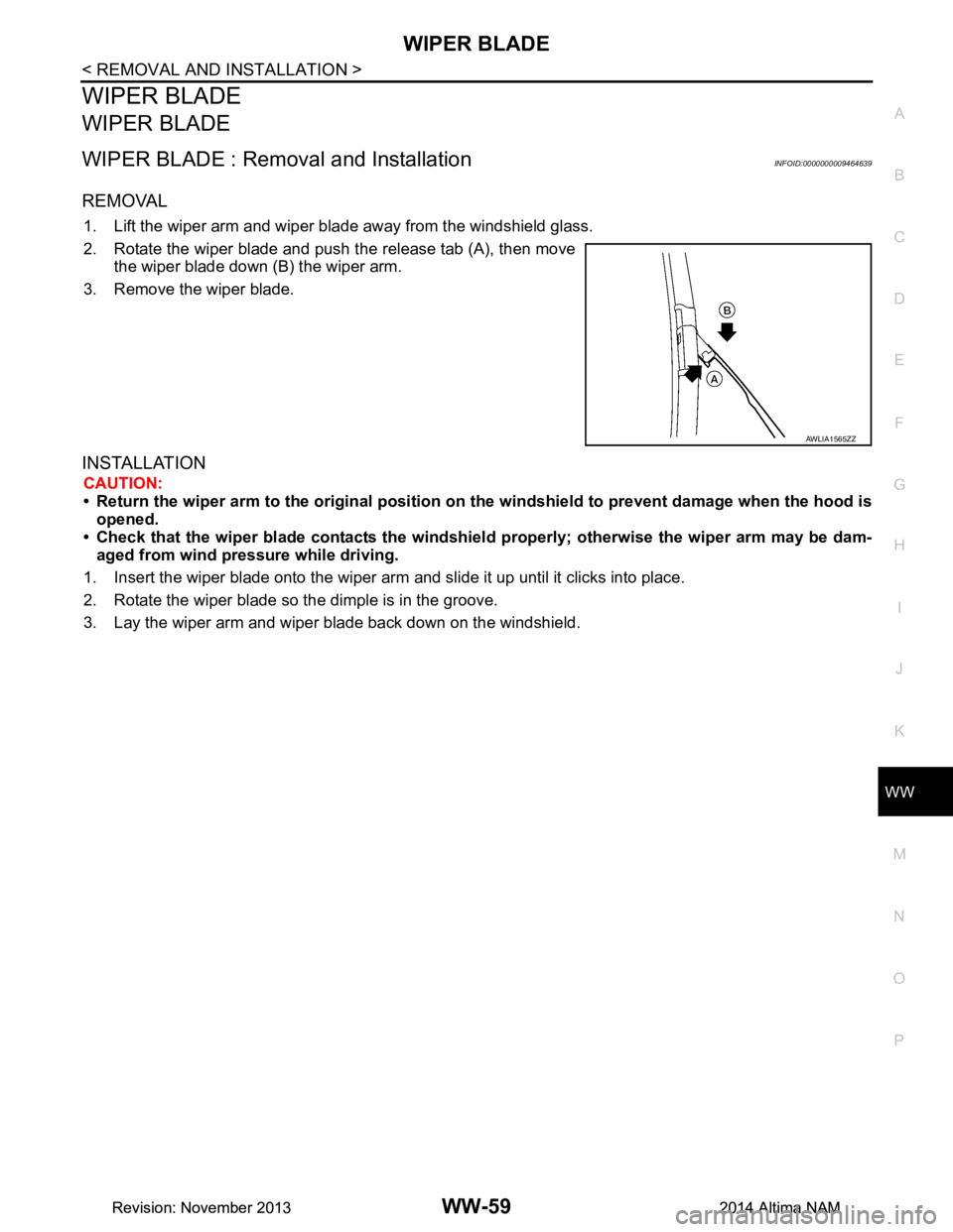
REMOVAL
1. Lift the wiper arm and wiper blade away from the windshield glass.
2. Rotate the wiper blade and push the release tab (A), then move the wiper blade down (B) the wiper arm.
3. Remove the wiper blade.
INSTALLATION
CAUTION:
• Return the wiper arm to the origin al position on the windshield to prevent damage when the hood is
opened.
• Check that the wiper blade contacts the windshiel d properly; otherwise the wiper arm may be dam-
aged from wind pressure while driving.
1. Insert the wiper blade onto the wiper arm and slide it up until it clicks into place.
2. Rotate the wiper blade so the dimple is in the groove.
3. Lay the wiper arm and wiper blade back down on the windshield.
AWLIA1565ZZ
Revision: November 20132014 Altima NAMRevision: November 20132014 Altima NAM