Page 4194 of 4801
STR-4
< SYSTEM DESCRIPTION >
COMPONENT PARTS
SYSTEM DESCRIPTION
COMPONENT PARTS
QR25DE
QR25DE : Component Parts LocationINFOID:0000000009461219
QR25DE : Component DescriptionINFOID:0000000009461220
VQ35DE
1. Transmission range switch 2. Starter motor 3. IPDM E/R
4. BCM (view with combination meter re- moved)
AWBIA1287ZZ
Component part Description
Transmission range switch Transmission range switch supplies power to the starter relay and
starter control relay inside the IPDM E/R when the shift selector is
placed in the P or N position.
BCM BCM controls the starter relay inside IPDM E/R.
IPDM E/R CPU inside IPDM E/R operates the starter relay when the ignition
switch is in the start position.
Starter motor The starter motor plunger closes and the motor is supplied with
battery power, which in turn cranks the engine, when the S termi-
nal is supplied with electric power.
Revision: November 20132014 Altima NAMRevision: November 20132014 Altima NAM
Page 4195 of 4801
COMPONENT PARTSSTR-5
< SYSTEM DESCRIPTION >
C
D E
F
G H
I
J
K L
M A
STR
NP
O
VQ35DE : Component Parts LocationINFOID:0000000009461221
VQ35DE : Component DescriptionINFOID:0000000009461222
Vehicle front
1. Starter motor 2. Transmission range switch 3. IPDM E/R
4. BCM (view combination meter re- moved)
AWBIA1288ZZ
Component part Description
Transmission range switch Transmission range switch supplies power to the starter relay and
starter control relay inside the IPDM E/R when the shift selector is
placed in the P or N position.
BCM BCM controls the starter relay inside IPDM E/R.
IPDM E/R CPU inside IPDM E/R operates the starter relay when the ignition
switch is in the start position.
Starter motor The starter motor plunger closes and the motor is supplied with
battery power, which in turn cranks the engine, when the S termi-
nal is supplied with electric power.
Revision: November 20132014 Altima NAMRevision: November 20132014 Altima NAM
Page 4775 of 4801

WW-40
< DTC/CIRCUIT DIAGNOSIS >
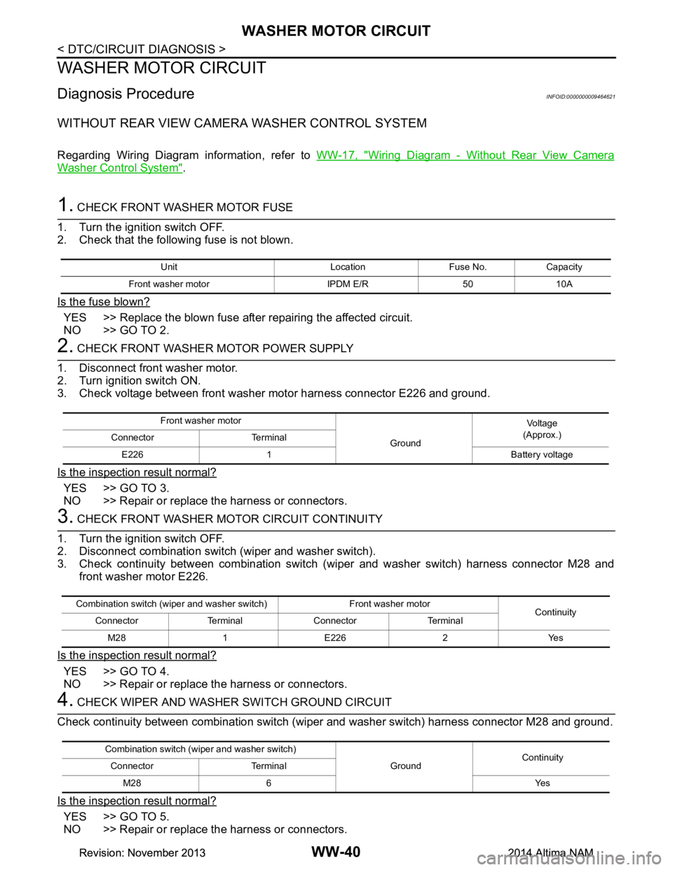
WASHER MOTOR CIRCUIT
WASHER MOTOR CIRCUIT
Diagnosis ProcedureINFOID:0000000009464621
WITHOUT REAR VIEW CAMERA WASHER CONTROL SYSTEM
Regarding Wiring Diagram information, refer to WW-17, "Wiring Diagram - Without Rear View Camera
Washer Control System".
1. CHECK FRONT WASHER MOTOR FUSE
1. Turn the ignition switch OFF.
2. Check that the following fuse is not blown.
Is the fuse blown?
YES >> Replace the blown fuse after repairing the affected circuit.
NO >> GO TO 2.
2. CHECK FRONT WASHER MOTOR POWER SUPPLY
1. Disconnect front washer motor.
2. Turn ignition switch ON.
3. Check voltage between front washer motor harness connector E226 and ground.
Is the inspection result normal?
YES >> GO TO 3.
NO >> Repair or replace the harness or connectors.
3. CHECK FRONT WASHER MOTOR CIRCUIT CONTINUITY
1. Turn the ignition switch OFF.
2. Disconnect combination switch (wiper and washer switch).
3. Check continuity between combination switch (wiper and washer switch) harness connector M28 and
front washer motor E226.
Is the inspection result normal?
YES >> GO TO 4.
NO >> Repair or replace the harness or connectors.
4. CHECK WIPER AND WASHER SWITCH GROUND CIRCUIT
Check continuity between combination switch (wiper and washer switch) harness connector M28 and ground.
Is the inspection result normal?
YES >> GO TO 5.
NO >> Repair or replace the harness or connectors.
Unit Location Fuse No. Capacity
Front washer motor IPDM E/R 50 10A
Front washer motor
GroundVo l ta g e
(Approx.)
Connector Terminal
E226 1 Battery voltage
Combination switch (wiper and washer switch) Front washer motor Continuity
Connector Terminal Connector Terminal
M281E2262 Yes
Combination switch (wiper and washer switch) GroundContinuity
Connector Terminal
M28 6 Yes
Revision: November 20132014 Altima NAMRevision: November 20132014 Altima NAM
Page 4776 of 4801

WASHER MOTOR CIRCUITWW-41
< DTC/CIRCUIT DIAGNOSIS >
C
D E
F
G H
I
J
K
M A
B
WW
N
O P
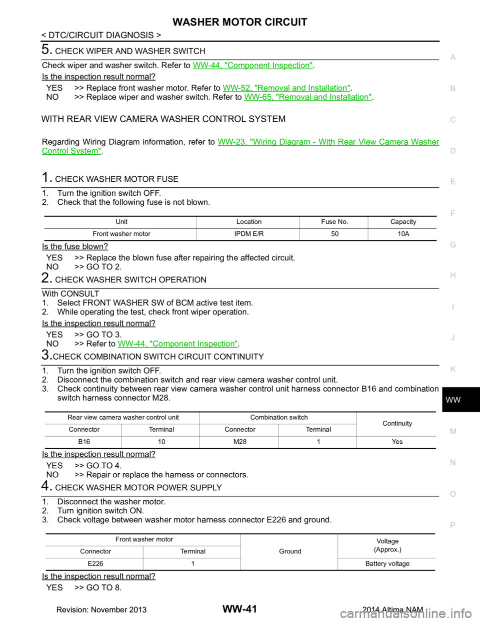
5. CHECK WIPER AND WASHER SWITCH
Check wiper and washer switch. Refer to WW-44, "Component Inspection"
.
Is the inspection result normal?
YES >> Replace front washer motor. Refer to WW-52, "Removal and Installation".
NO >> Replace wiper and washer switch. Refer to WW-65, "Removal and Installation"
.
WITH REAR VIEW CAMERA WASHER CONTROL SYSTEM
Regarding Wiring Diagram information, refer to WW-23, "Wiring Diagram - With Rear View Camera Washer
Control System".
1. CHECK WASHER MOTOR FUSE
1. Turn the ignition switch OFF.
2. Check that the following fuse is not blown.
Is the fuse blown?
YES >> Replace the blown fuse after repairing the affected circuit.
NO >> GO TO 2.
2. CHECK WASHER SWITCH OPERATION
With CONSULT
1. Select FRONT WASHER SW of BCM active test item.
2. While operating the test, check front wiper operation.
Is the inspection result normal?
YES >> GO TO 3.
NO >> Refer to WW-44, "Component Inspection"
.
3.CHECK COMBINATION SWITCH CIRCUIT CONTINUITY
1. Turn the ignition switch OFF.
2. Disconnect the combination switch and rear view camera washer control unit.
3. Check continuity between rear view camera was her control unit harness connector B16 and combination
switch harness connector M28.
Is the inspection result normal?
YES >> GO TO 4.
NO >> Repair or replace the harness or connectors.
4. CHECK WASHER MOTOR POWER SUPPLY
1. Disconnect the washer motor.
2. Turn ignition switch ON.
3. Check voltage between washer motor harness connector E226 and ground.
Is the inspection result normal?
YES >> GO TO 8.
Unit Location Fuse No. Capacity
Front washer motor IPDM E/R 50 10A
Rear view camera washer control unit Combination switch Continuity
Connector Terminal Connector Terminal
B16 10 M28 1 Yes
Front washer motor GroundVoltag e
(Approx.)
Connector Terminal
E226 1 Battery voltage
Revision: November 20132014 Altima NAMRevision: November 20132014 Altima NAM