2014 NISSAN TEANA battery location
[x] Cancel search: battery locationPage 2454 of 4801
FAX-2
< PRECAUTION >
PRECAUTIONS
PRECAUTION
PRECAUTIONS
Precaution for Supplemental Restraint System (SRS) "AIR BAG" and "SEAT BELT
PRE-TENSIONER"
INFOID:0000000009951700
The Supplemental Restraint System such as “A IR BAG” and “SEAT BELT PRE-TENSIONER”, used along
with a front seat belt, helps to reduce the risk or severi ty of injury to the driver and front passenger for certain
types of collision. Information necessary to service the system safely is included in the SR and SB section of
this Service Manual.
WARNING:
• To avoid rendering the SRS inopera tive, which could increase the risk of personal injury or death in
the event of a collision which would result in air bag inflation, all maintenance must be performed by
an authorized NISS AN/INFINITI dealer.
• Improper maintenance, including in correct removal and installation of the SRS, can lead to personal
injury caused by unintent ional activation of the system. For re moval of Spiral Cable and Air Bag
Module, see the SR section.
• Do not use electrical test equipmen t on any circuit related to the SRS unless instructed to in this
Service Manual. SRS wiring harn esses can be identified by yellow and/or orange harnesses or har-
ness connectors.
PRECAUTIONS WHEN USING POWER TOOLS (AIR OR ELECTRIC) AND HAMMERS
WARNING:
• When working near the Airbag Diagnosis Sensor Unit or other Airbag System sensors with the Igni-
tion ON or engine running, DO NOT use air or electri c power tools or strike near the sensor(s) with a
hammer. Heavy vibration could activate the sensor( s) and deploy the air bag(s), possibly causing
serious injury.
• When using air or electric power tools or hammers , always switch the Ignition OFF, disconnect the
battery and wait at least three minutes before performing any service.
Precautions for Drive ShaftINFOID:0000000009464432
Observe the following precautions when disassembling and assembling drive shaft.
• Joint sub-assembly does not disass emble because it is non-overhaul parts.
• Perform work in a location which is as dust-free as possible.
• Before disassembling and assembling, clean the outside of parts.
• Prevention of the entry of foreign objects must be tak en into account during disassembly of the service loca-
tion.
• Disassembled parts must be carefully reassembled in the correct order. If work is interrupted, a clean cover must be placed over parts.
• Paper shop cloths must be used. Fabric shop cloths must not be used because of the danger of lint adhering
to parts.
• Disassembled parts (except for rubber parts) should be cleaned with kerosene which shall be removed by
blowing with air or wiping with paper shop cloths.
Revision: November 20132014 Altima NAM
Page 2534 of 4801
GI-6
< HOW TO USE THIS MANUAL >
HOW TO FOLLOW TROUBLE DIAGNOSES
HOW TO FOLLOW TROUBLE DIAGNOSES
DescriptionINFOID:0000000009462973
NOTICE:
Trouble diagnoses indicate work procedures required to diagnose problems effectively. Observe the following
instructions before diagnosing.
• Before performing trouble diagnoses, read the “Work Flow” in each section.
• After repairs, re-check that the problem has been completely eliminated.
• Refer to Component Parts and Harness Connector Locat ion for the Systems described in each section for
identification/location of components and harness connectors.
• When checking circuit continuity, ignition switch should be OFF.
• Refer to the Circuit Diagram for quick pinpoint check.
If you need to check circuit continui ty between harness connectors in more detail, such as when a sub-har-
ness is used, refer to Wiring Diagram in each individual section and Harness Layout in PG section for identi-
fication of harness connectors.
• Before checking voltage at connectors, check battery voltage.
• After accomplishing the Diagnosis Procedures and Elec trical Components Inspection, make sure that all
harness connectors are reconnected as they were.
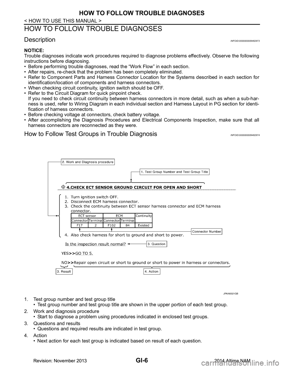
How to Follow Test Grou ps in Trouble DiagnosisINFOID:0000000009462974
1. Test group number and test group title
• Test group number and test group title are s hown in the upper portion of each test group.
2. Work and diagnosis procedure • Start to diagnose a problem using procedur es indicated in enclosed test groups.
3. Questions and results • Questions and required results are indicated in test group.
4. Action • Next action for each test group is indicated based on result of each question.
JPAIA0021GB
Revision: November 20132014 Altima NAMRevision: November 20132014 Altima NAM
Page 2556 of 4801
GI-28
< PRECAUTION >
PRECAUTIONS
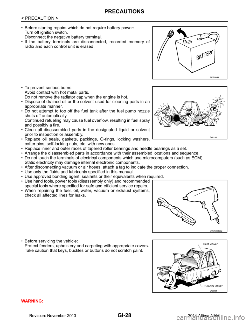
• Before starting repairs which do not require battery power:Turn off ignition switch.
Disconnect the negative battery terminal.
• If the battery terminals are disconnected, recorded memory of
radio and each control unit is erased.
• To prevent serious burns: Avoid contact with hot metal parts.
Do not remove the radiator cap when the engine is hot.
• Dispose of drained oil or the solvent used for cleaning parts in an
appropriate manner.
• Do not attempt to top off the fuel tank after the fuel pump nozzle
shuts off automatically.
Continued refueling may cause fuel overflow, resulting in fuel spray
and possibly a fire.
• Clean all disassembled parts in the designated liquid or solvent
prior to inspection or assembly.
• Replace oil seals, gaskets, packings, O-rings, locking washers, cotter pins, self-locking nuts, etc. with new ones.
• Replace inner and outer races of tapered roller bearings and needle bearings as a set.
• Arrange the disassembled parts in accordance with their assembled locations and sequence.
• Do not touch the terminals of electrical com ponents which use microcomputers (such as ECM).
Static electricity may damage internal electronic components.
• After disconnecting vacuum or air hoses, atta ch a tag to indicate the proper connection.
• Use only the fluids and lubricants specified in this manual.
• Use approved bonding agent, sealants or their equivalents when required.
• Use hand tools, power tools (disassembly only) and recommended special tools where specified for safe and efficient service repairs.
• When repairing the fuel, oil, water, vacuum or exhaust systems,
check all affected lines for leaks.
• Before servicing the vehicle: Protect fenders, upholstery and carpeting with appropriate covers.
Take caution that keys, buckles or buttons do not scratch paint.
WARNING:
SEF289H
SGI233
JPAIA0335ZZ
SGI234
Revision: November 20132014 Altima NAMRevision: November 20132014 Altima NAM
Page 2822 of 4801
INL-1
DRIVER CONTROLS
C
D E
F
G H
I
J
K
M
SECTION INL
A
B
INL
N
O P
CONTENTS
INTERIOR LIGHTING SYSTEM
PRECAUTION ................ ...............................3
PRECAUTIONS .............................................. .....3
Precaution for Supplemental Restraint System
(SRS) "AIR BAG" and "SEAT BELT PRE-TEN-
SIONER" ............................................................. ......
3
Precaution for Work ..................................................3
PREPARATION ............................................4
PREPARATION .............................................. .....4
Special Service Tool ........................................... ......4
SYSTEM DESCRIPTION ..............................5
COMPONENT PARTS ................................... .....5
Component Parts Location .................................. ......5
Component Description .............................................5
INTERIOR ROOM LAMP CONTROL SYSTEM
.....
7
System Diagram .................................................. ......7
System Description ...................................................7
ILLUMINATION CONTROL SYSTEM .................9
System Diagram .................................................. ......9
System Description ...................................................9
DIAGNOSIS SYSTEM (BCM) ............................11
COMMON ITEM ..................................................... ....11
COMMON ITEM : CONSULT Function (BCM -
COMMON ITEM) ................................................. ....
11
INT LAMP .............................................................. ....12
INT LAMP : CONSULT Function (BCM - INT
LAMP) ................................................................. ....
12
BATTERY SAVER ................................................. ....13
BATTERY SAVER : CONSULT Function (BCM -
BATTERY SAVER) ............ .....................................
13
INTELLIGENT KEY ............................................... ....13
INTELLIGENT KEY : CONSULT Function (BCM -
INTELLIGENT KEY) ........... .....................................
13
DIAGNOSIS SYSTEM (IPDM E/R) ...................17
Diagnosis Description .......................................... ....17
CONSULT Function (IPDM E/R) .............................18
ECU DIAGNOSIS INFORMATION ..............21
BCM, IPDM E/R .................................................21
List of ECU Reference ......................................... ....21
WIRING DIAGRAM ......................................22
INTERIOR ROOM LAMP ..................................22
Wiring Diagram .................................................... ....22
ILLUMINATION .................................................33
Wiring Diagram ........................................................33
BASIC INSPECTION ...................................47
DIAGNOSIS AND REPAIR WORKFLOW ........47
Work Flow ............................................................ ....47
DTC/CIRCUIT DIAGNOSIS .........................50
POWER SUPPLY AND GROUND CIRCUIT ....50
BCM ....................................................................... ....50
BCM : Diagnosis Procedure ....................................50
IPDM E/R ................................................................ ....50
IPDM E/R : Diagnosis Procedure ............................50
BATTERY SAVER OUTPUT/POWER SUP-
PLY CIRCUIT ....................................................
52
Description ........................................................... ....52
Component Function Check ....................................52
Diagnosis Procedure ...............................................52
INTERIOR ROOM LAMP CONTROL CIRCUIT
...
54
Description ........................................................... ....54
Revision: November 20132014 Altima NAMRevision: November 20132014 Altima NAM
Page 3433 of 4801
PG
PG-1
ELECTRICAL & POWER CONTROL
C
D E
F
G H
I
J
K L
B
SECTION PG
A
O P
N
CONTENTS
POWER SUPPLY, GROUND & CIRCUIT ELEMENTS
PRECAUTION ................
...............................2
PRECAUTIONS .............................................. .....2
Precaution for Supplemental Restraint System
(SRS) "AIR BAG" and "SEAT BELT PRE-TEN-
SIONER" ............................................................. ......
2
PREPARATION ............................................3
PREPARATION .............................................. .....3
Special Service Tool ........................................... ......3
Commercial Service Tool ..........................................3
BASIC INSPECTION ....................................4
BATTERY ....................................................... .....4
How to Handle Battery ........................................ ......4
Work Flow ........................................................... ......4
INSPECTION AND ADJUSTMENT .....................7
ADDITIONAL SERVICE WHEN REMOVING BAT-
TERY NEGATIVE TERMINAL ............................... ......
7
ADDITIONAL SERVICE WHEN REMOVING
BATTERY NEGATIVE TERMINAL : Special Re-
pair Requirement ................................................. ......
7
DTC/CIRCUIT DIAGNOSIS ..........................8
POWER SUPPLY ROUTING CIRCUIT .......... .....8
Wiring Diagram — Battery Power Supply — ....... ......8
Wiring Diagram — Accessory Power Supply — .....15
Wiring Diagram — Ignition Power Supply — ..........19
Fuse ........................................................................28
Fusible Link .............................................................28
GROUND ...........................................................29
Ground Distribution .............................................. ....29
HARNESS .........................................................39
Harness Layout ................................................... ....39
ELECTRICAL UNITS LOCATION ....................61
Electrical Units Location ..........................................61
HARNESS CONNECTOR .................................65
Description ...............................................................65
STANDARDIZED RELAY .................................68
Description ...............................................................68
FUSE BLOCK - JUNCTION BOX (J/B) ............70
Terminal Arrangement .............................................70
FUSE, FUSIBLE LINK AND RELAY BOX ........71
Terminal Arrangement .............................................71
IPDM E/R (INTELLIGENT POWER DISTRI-
BUTION MODULE ENGINE ROOM) ................
72
Fuse, Connector and Terminal Arrangement ...... ....72
REMOVAL AND INSTALLATION ...............73
BATTERY ..........................................................73
Exploded View ..................................................... ....73
Removal and Installation (Battery) ..........................73
Removal and Installation (Battery Tray) ..................74
SERVICE DATA AND SPECIFICATIONS
(SDS) ............... .............................................
75
BATTERY ..........................................................75
Battery ................................................................. ....75
Revision: November 20132014 Altima NAM
Page 3508 of 4801
PWC-1
BODY EXTERIOR, DOORS, ROOF & VEHICLE SECURITY
C
D E
F
G H
I
J
L
M
SECTION PWC
A
B
PWC
N
O P
CONTENTS
POWER WINDOW CONTROL SYSTEM
LH FRONT ONLY ANTI-PINCH
PRECAUTION ................ ...............................
6
PRECAUTIONS .............................................. .....6
Precaution for Supplemental Restraint System
(SRS) "AIR BAG" and "SEAT BELT PRE-TEN-
SIONER" ............................................................. ......
6
Precaution for Work ..................................................6
PREPARATION ............................................7
PREPARATION .............................................. .....7
Special Service Tool ........................................... ......7
SYSTEM DESCRIPTION ..............................8
COMPONENT PARTS ................................... .....8
Component Parts Location ................................ ......8
Component Description .............................................8
SYSTEM .............................................................10
System Diagram ................................................. ....10
System Description .................................................10
Fail-safe ..................................................................11
DIAGNOSIS SYSTEM (BCM) ............................13
COMMON ITEM ..................................................... ....13
COMMON ITEM : CONSULT Function (BCM -
COMMON ITEM) ................................................. ....
13
RETAINED PWR ................................................... ....14
RETAINED PWR : CONSULT Function (BCM -
RETAINED PWR) ............................................... ....
14
ECU DIAGNOSIS INFORMATION ..............15
BCM (BODY CONTROL MODULE) ............... ....15
List of ECU Reference ........................................ ....15
POWER WINDOW MAIN SWITCH ....................16
Reference Value ................................................. ....16
WIRING DIAGRAM ......................................18
POWER WINDOW SYSTEM .............................18
Wiring Diagram - With Left Front Only Power Win-
dow Anti- Pinch .................................................... ....
18
BASIC INSPECTION ...................................25
DIAGNOSIS AND REPAIR WORKFLOW ........25
Work Flow ............................................................ ....25
INSPECTION AND ADJUSTMENT ..................27
ADDITIONAL SERVICE WHEN REMOVING BAT-
TERY NEGATIVE TERMINAL ............................... ....
27
ADDITIONAL SERVICE WHEN REMOVING
BATTERY NEGATIVE TERMINAL : Description . ....
27
ADDITIONAL SERVICE WHEN REMOVING
BATTERY NEGATIVE TERMINAL : Special Re-
pair Requirement ................................................. ....
27
ADDITIONAL SERVICE WHEN REPLACING
CONTROL UNIT .................................................... ....
27
ADDITIONAL SERVICE WHEN REPLACING
CONTROL UNIT : Description ............................. ....
27
ADDITIONAL SERVICE WHEN REPLACING
CONTROL UNIT : Special Repair Requirement .. ....
27
DTC/CIRCUIT DIAGNOSIS .........................29
POWER SUPPLY AND GROUND CIRCUIT ....29
BCM ....................................................................... ....29
BCM : Diagnosis Procedure ....................................29
POWER WINDOW MAIN SWITCH ........................ ....29
POWER WINDOW MAIN SWITCH : Description ....29
POWER WINDOW MAIN SWITCH : Component
Function Check .................................................... ....
30
POWER WINDOW MAIN SWITCH : Diagnosis
Procedure ............................................................ ....
30
POWER WINDOW MAIN SWITCH : Component
Inspection ............................................................ ....
33
Revision: November 20132014 Altima NAMRevision: November 20132014 Altima NAM
Page 3510 of 4801
PWC-3
C
D E
F
G H
I
J
L
M A
B
PWC
N
O P
MAIN POWER WINDOW AND DOOR LOCK/
UNLOCK SWITCH ......................................... ....
65
Removal and Installation .........................................65
POWER WINDOW AND DOOR LOCK/UN-
LOCK SWITCH RH ........................................ ....
66
Removal and Installation .........................................66
REAR POWER WINDOW SWITCH ............... ....67
Removal and Installation .........................................67
LH & RH FRONT ANTI-PINCH
PRECAUTION ................ ..............................
68
PRECAUTIONS .............................................. ....68
Precaution for Supplemental Restraint System
(SRS) "AIR BAG" and "SEAT BELT PRE-TEN-
SIONER" ............................................................. ....
68
Precaution for Work ................................................68
PREPARATION ...........................................69
PREPARATION .............................................. ....69
Special Service Tool ........................................... ....69
SYSTEM DESCRIPTION .............................70
COMPONENT PARTS ................................... ....70
Component Parts Location ................................ ....70
Component Description ...........................................70
SYSTEM .............................................................72
System Diagram ................................................. ....72
System Description .................................................72
Fail-safe ..................................................................74
DIAGNOSIS SYSTEM (BCM) ............................75
COMMON ITEM ..................................................... ....75
COMMON ITEM : CONSULT Function (BCM -
COMMON ITEM) ................................................. ....
75
RETAINED PWR ................................................... ....76
RETAINED PWR : CONSULT Function (BCM -
RETAINED PWR) ............................................... ....
76
ECU DIAGNOSIS INFORMATION ..............77
BCM (BODY CONTROL MODULE) ............... ....77
List of ECU Reference ........................................ ....77
POWER WINDOW MAIN SWITCH ....................78
Reference Value ................................................. ....78
Fail Safe .................................................................79
FRONT POWER WINDOW SWITCH .................81
Reference Value ................................................. ....81
Fail Safe .................................................................82
WIRING DIAGRAM ......................................83
POWER WINDOW SYSTEM .......................... ....83
Wiring Diagram - With Left And Right Front Power
Window Anti-Pinch .............................................. ....
83
BASIC INSPECTION ...................................91
DIAGNOSIS AND REPAIR WORKFLOW ........91
Work Flow ............................................................ ....91
INSPECTION AND ADJUSTMENT ..................93
ADDITIONAL SERVICE WHEN REMOVING BAT-
TERY NEGATIVE TERMINAL ............................... ....
93
ADDITIONAL SERVICE WHEN REMOVING
BATTERY NEGATIVE TERMINAL : Description . ....
93
ADDITIONAL SERVICE WHEN REMOVING
BATTERY NEGATIVE TERMINAL : Special Re-
pair Requirement ................................................. ....
93
ADDITIONAL SERVICE WHEN REPLACING
CONTROL UNIT .................................................... ....
93
ADDITIONAL SERVICE WHEN REPLACING
CONTROL UNIT : Description ............................. ....
93
ADDITIONAL SERVICE WHEN REPLACING
CONTROL UNIT : Special Repair Requirement .. ....
93
DTC/CIRCUIT DIAGNOSIS .........................95
POWER SUPPLY AND GROUND CIRCUIT ....95
BCM ....................................................................... ....95
BCM : Diagnosis Procedure ....................................95
POWER WINDOW MAIN SWITCH ........................ ....95
POWER WINDOW MAIN SWITCH : Description ....95
POWER WINDOW MAIN SWITCH : Component
Function Check .................................................... ....
96
POWER WINDOW MAIN SWITCH : Diagnosis
Procedure ............................................................ ....
96
POWER WINDOW MAIN SWITCH : Component
Inspection ............................................................ ....
98
POWER WINDOW MAIN SWITCH : Special Re-
pair Requirement ................................................. ....
99
FRONT POWER WINDOW SWITCH ..................... ....99
FRONT POWER WINDOW SWITCH : Descrip-
tion ....................................................................... ....
99
FRONT POWER WINDOW SWITCH : Compo-
nent Function Check ............................................ ..
100
FRONT POWER WINDOW SWITCH : Diagnosis
Procedure ............................................................ ..
100
FRONT POWER WINDOW SWITCH : Special
Repair Requirement ............................................ ..
101
REAR POWER WINDOW SWITCH ....................... ..101
REAR POWER WINDOW SWITCH : Description ..101
REAR POWER WINDOW SWITCH : Component
Function Check .................................................... ..
101
REAR POWER WINDOW SWITCH : Diagnosis
Procedure ............................................................ ..
101
REAR POWER WINDOW SWITCH : Component
Inspection ............................................................ ..
103
Revision: November 20132014 Altima NAMRevision: November 20132014 Altima NAM
Page 3776 of 4801
FRONT SEATSE-27
< REMOVAL AND INSTALLATION >
C
D E
F
G H
I
K L
M A
B
SE
N
O P
CAUTION:
Make sure that the seat harness or the floor trim is not damaged during installation.
DRIVER SIDE : Removal and Installation - Seatback BoardINFOID:0000000009462935
REMOVAL
CAUTION:
• Before servicing, turn ignition swit ch OFF, disconnect both battery terminals and wait at least three
minutes.
• Always work from the side or back of the seat back assembly, do not work in front of seat.
1. Slide the seat to the full forward position.
2. Disconnect the negative and positive battery terminal s and wait at least three minutes. Refer to PG-73,
"Removal and Installation (Battery)".
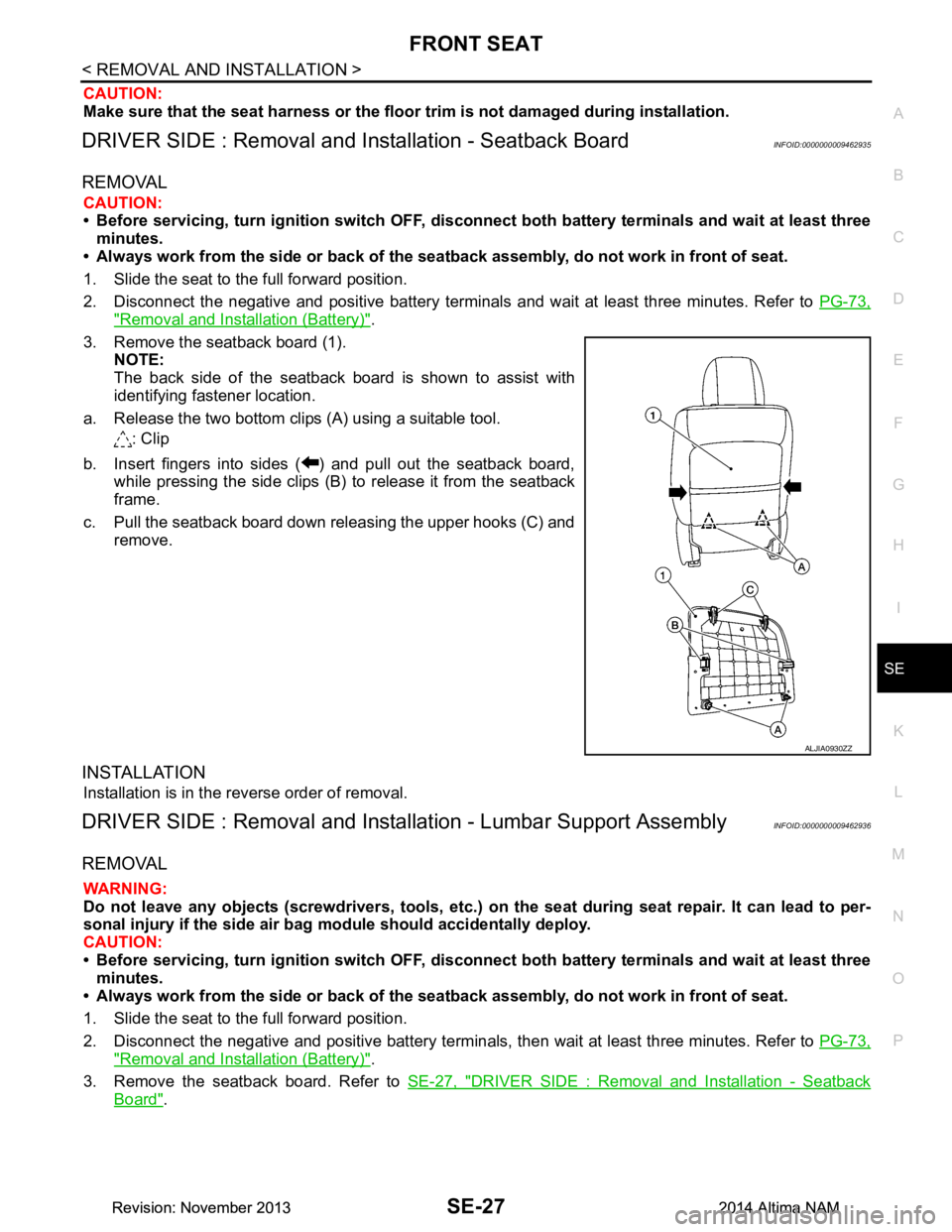
3. Remove the seatback board (1). NOTE:
The back side of the seatback boar d is shown to assist with
identifying fastener location.
a. Release the two bottom clips (A) using a suitable tool. : Clip
b. Insert fingers into sides ( ) and pull out the seatback board, while pressing the side clips (B) to release it from the seatback
frame.
c. Pull the seatback board down releasing the upper hooks (C) and remove.
INSTALLATION
Installation is in the reverse order of removal.
DRIVER SIDE : Removal and Installation - Lumbar Support AssemblyINFOID:0000000009462936
REMOVAL
WARNING:
Do not leave any objects (screwdriver s, tools, etc.) on the seat during seat repair. It can lead to per-
sonal injury if the side air bag module should accidentally deploy.
CAUTION:
• Before servicing, turn ignition swit ch OFF, disconnect both battery terminals and wait at least three
minutes.
• Always work from the side or back of the seat back assembly, do not work in front of seat.
1. Slide the seat to the full forward position.
2. Disconnect the negative and positive bat tery terminals, then wait at least three minutes. Refer to PG-73,
"Removal and Installation (Battery)".
3. Remove the seatback board. Refer to SE-27, "DRIVER SIDE : Removal and Installation - Seatback
Board".
ALJIA0930ZZ
Revision: November 20132014 Altima NAMRevision: November 20132014 Altima NAM