2014 NISSAN TEANA seat adjustment
[x] Cancel search: seat adjustmentPage 3508 of 4801
PWC-1
BODY EXTERIOR, DOORS, ROOF & VEHICLE SECURITY
C
D E
F
G H
I
J
L
M
SECTION PWC
A
B
PWC
N
O P
CONTENTS
POWER WINDOW CONTROL SYSTEM
LH FRONT ONLY ANTI-PINCH
PRECAUTION ................ ...............................
6
PRECAUTIONS .............................................. .....6
Precaution for Supplemental Restraint System
(SRS) "AIR BAG" and "SEAT BELT PRE-TEN-
SIONER" ............................................................. ......
6
Precaution for Work ..................................................6
PREPARATION ............................................7
PREPARATION .............................................. .....7
Special Service Tool ........................................... ......7
SYSTEM DESCRIPTION ..............................8
COMPONENT PARTS ................................... .....8
Component Parts Location ................................ ......8
Component Description .............................................8
SYSTEM .............................................................10
System Diagram ................................................. ....10
System Description .................................................10
Fail-safe ..................................................................11
DIAGNOSIS SYSTEM (BCM) ............................13
COMMON ITEM ..................................................... ....13
COMMON ITEM : CONSULT Function (BCM -
COMMON ITEM) ................................................. ....
13
RETAINED PWR ................................................... ....14
RETAINED PWR : CONSULT Function (BCM -
RETAINED PWR) ............................................... ....
14
ECU DIAGNOSIS INFORMATION ..............15
BCM (BODY CONTROL MODULE) ............... ....15
List of ECU Reference ........................................ ....15
POWER WINDOW MAIN SWITCH ....................16
Reference Value ................................................. ....16
WIRING DIAGRAM ......................................18
POWER WINDOW SYSTEM .............................18
Wiring Diagram - With Left Front Only Power Win-
dow Anti- Pinch .................................................... ....
18
BASIC INSPECTION ...................................25
DIAGNOSIS AND REPAIR WORKFLOW ........25
Work Flow ............................................................ ....25
INSPECTION AND ADJUSTMENT ..................27
ADDITIONAL SERVICE WHEN REMOVING BAT-
TERY NEGATIVE TERMINAL ............................... ....
27
ADDITIONAL SERVICE WHEN REMOVING
BATTERY NEGATIVE TERMINAL : Description . ....
27
ADDITIONAL SERVICE WHEN REMOVING
BATTERY NEGATIVE TERMINAL : Special Re-
pair Requirement ................................................. ....
27
ADDITIONAL SERVICE WHEN REPLACING
CONTROL UNIT .................................................... ....
27
ADDITIONAL SERVICE WHEN REPLACING
CONTROL UNIT : Description ............................. ....
27
ADDITIONAL SERVICE WHEN REPLACING
CONTROL UNIT : Special Repair Requirement .. ....
27
DTC/CIRCUIT DIAGNOSIS .........................29
POWER SUPPLY AND GROUND CIRCUIT ....29
BCM ....................................................................... ....29
BCM : Diagnosis Procedure ....................................29
POWER WINDOW MAIN SWITCH ........................ ....29
POWER WINDOW MAIN SWITCH : Description ....29
POWER WINDOW MAIN SWITCH : Component
Function Check .................................................... ....
30
POWER WINDOW MAIN SWITCH : Diagnosis
Procedure ............................................................ ....
30
POWER WINDOW MAIN SWITCH : Component
Inspection ............................................................ ....
33
Revision: November 20132014 Altima NAMRevision: November 20132014 Altima NAM
Page 3510 of 4801
PWC-3
C
D E
F
G H
I
J
L
M A
B
PWC
N
O P
MAIN POWER WINDOW AND DOOR LOCK/
UNLOCK SWITCH ......................................... ....
65
Removal and Installation .........................................65
POWER WINDOW AND DOOR LOCK/UN-
LOCK SWITCH RH ........................................ ....
66
Removal and Installation .........................................66
REAR POWER WINDOW SWITCH ............... ....67
Removal and Installation .........................................67
LH & RH FRONT ANTI-PINCH
PRECAUTION ................ ..............................
68
PRECAUTIONS .............................................. ....68
Precaution for Supplemental Restraint System
(SRS) "AIR BAG" and "SEAT BELT PRE-TEN-
SIONER" ............................................................. ....
68
Precaution for Work ................................................68
PREPARATION ...........................................69
PREPARATION .............................................. ....69
Special Service Tool ........................................... ....69
SYSTEM DESCRIPTION .............................70
COMPONENT PARTS ................................... ....70
Component Parts Location ................................ ....70
Component Description ...........................................70
SYSTEM .............................................................72
System Diagram ................................................. ....72
System Description .................................................72
Fail-safe ..................................................................74
DIAGNOSIS SYSTEM (BCM) ............................75
COMMON ITEM ..................................................... ....75
COMMON ITEM : CONSULT Function (BCM -
COMMON ITEM) ................................................. ....
75
RETAINED PWR ................................................... ....76
RETAINED PWR : CONSULT Function (BCM -
RETAINED PWR) ............................................... ....
76
ECU DIAGNOSIS INFORMATION ..............77
BCM (BODY CONTROL MODULE) ............... ....77
List of ECU Reference ........................................ ....77
POWER WINDOW MAIN SWITCH ....................78
Reference Value ................................................. ....78
Fail Safe .................................................................79
FRONT POWER WINDOW SWITCH .................81
Reference Value ................................................. ....81
Fail Safe .................................................................82
WIRING DIAGRAM ......................................83
POWER WINDOW SYSTEM .......................... ....83
Wiring Diagram - With Left And Right Front Power
Window Anti-Pinch .............................................. ....
83
BASIC INSPECTION ...................................91
DIAGNOSIS AND REPAIR WORKFLOW ........91
Work Flow ............................................................ ....91
INSPECTION AND ADJUSTMENT ..................93
ADDITIONAL SERVICE WHEN REMOVING BAT-
TERY NEGATIVE TERMINAL ............................... ....
93
ADDITIONAL SERVICE WHEN REMOVING
BATTERY NEGATIVE TERMINAL : Description . ....
93
ADDITIONAL SERVICE WHEN REMOVING
BATTERY NEGATIVE TERMINAL : Special Re-
pair Requirement ................................................. ....
93
ADDITIONAL SERVICE WHEN REPLACING
CONTROL UNIT .................................................... ....
93
ADDITIONAL SERVICE WHEN REPLACING
CONTROL UNIT : Description ............................. ....
93
ADDITIONAL SERVICE WHEN REPLACING
CONTROL UNIT : Special Repair Requirement .. ....
93
DTC/CIRCUIT DIAGNOSIS .........................95
POWER SUPPLY AND GROUND CIRCUIT ....95
BCM ....................................................................... ....95
BCM : Diagnosis Procedure ....................................95
POWER WINDOW MAIN SWITCH ........................ ....95
POWER WINDOW MAIN SWITCH : Description ....95
POWER WINDOW MAIN SWITCH : Component
Function Check .................................................... ....
96
POWER WINDOW MAIN SWITCH : Diagnosis
Procedure ............................................................ ....
96
POWER WINDOW MAIN SWITCH : Component
Inspection ............................................................ ....
98
POWER WINDOW MAIN SWITCH : Special Re-
pair Requirement ................................................. ....
99
FRONT POWER WINDOW SWITCH ..................... ....99
FRONT POWER WINDOW SWITCH : Descrip-
tion ....................................................................... ....
99
FRONT POWER WINDOW SWITCH : Compo-
nent Function Check ............................................ ..
100
FRONT POWER WINDOW SWITCH : Diagnosis
Procedure ............................................................ ..
100
FRONT POWER WINDOW SWITCH : Special
Repair Requirement ............................................ ..
101
REAR POWER WINDOW SWITCH ....................... ..101
REAR POWER WINDOW SWITCH : Description ..101
REAR POWER WINDOW SWITCH : Component
Function Check .................................................... ..
101
REAR POWER WINDOW SWITCH : Diagnosis
Procedure ............................................................ ..
101
REAR POWER WINDOW SWITCH : Component
Inspection ............................................................ ..
103
Revision: November 20132014 Altima NAMRevision: November 20132014 Altima NAM
Page 3666 of 4801

RF-1
BODY EXTERIOR, DOORS, ROOF & VEHICLE SECURITY
C
D E
F
G H
I
J
L
M
SECTION RF
A
B
RF
N
O P
CONTENTS
ROOF
PRECAUTION ................ ...............................3
PRECAUTIONS .............................................. .....3
Precaution for Supplemental Restraint System
(SRS) "AIR BAG" and "SEAT BELT PRE-TEN-
SIONER" ............................................................. ......
3
Precaution for Work ..................................................3
PREPARATION ............................................4
PREPARATION .............................................. .....4
Special Service Tools ........................................ ......4
Commercial Service Tools .......................................4
SYSTEM DESCRIPTION ..............................5
COMPONENT PARTS ................................... .....5
MOONROOF .......................................................... ......5
MOONROOF : Component Parts Location .............5
MOONROOF : Component Description ...................5
SYSTEM ..............................................................6
MOONROOF .......................................................... ......6
MOONROOF : System Diagram ..............................6
MOONROOF : System Description ...........................6
DIAGNOSIS SYSTEM (BCM) .............................8
COMMON ITEM ..................................................... ......8
COMMON ITEM : CONSULT Function (BCM -
COMMON ITEM) ................................................. ......
8
RETAINED PWR ................................................... ......8
RETAINED PWR : CONSULT Function (BCM -
RETAINED PWR) ............................................... ......
9
ECU DIAGNOSIS INFORMATION ..............10
BCM (BODY CONTROL MODULE) ............... ....10
List of ECU Reference ........................................ ....10
MOONROOF MOTOR ASSEMBLY ...................11
Reference Value .................................................. ....11
WIRING DIAGRAM ......................................12
MOONROOF SYSTEM .....................................12
Wiring Diagram .................................................... ....12
BASIC INSPECTION ...................................18
DIAGNOSIS AND REPAIR WORKFLOW ........18
Work Flow ............................................................ ....18
INSPECTION AND ADJUSTMENT ..................20
ADDITIONAL SERVICE WHEN REPLACING
CONTROL UNIT .................................................... ....
20
ADDITIONAL SERVICE WHEN REPLACING
CONTROL UNIT : Description ............................. ....
20
ADDITIONAL SERVICE WHEN REPLACING
CONTROL UNIT : Special Repair Requirement .. ....
20
DTC/CIRCUIT DIAGNOSIS .........................21
POWER SUPPLY AND GROUND CIRCUIT ....21
BCM ....................................................................... ....21
BCM : Diagnosis Procedure ....................................21
MOONROOF MOTOR ASSEMBLY ...........................21
MOONROOF MOTOR ASSEM BLY : Description ....21
MOONROOF MO TOR ASSEMBLY :
Component Function Check .............................. ....
22
MOONROOF MOTOR ASSEMBLY :
Diagnosis Procedure .......................................... ....
22
MOONROOF MOTOR ASSEMBLY : Component
Inspection ............................................................ ....
24
MOONROOF MOTOR ASSEMBLY : Special Re-
pair Requirement ................................................. ....
25
MOONROOF SWITCH ......................................26
Description ...............................................................26
Diagnosis Procedure ..............................................26
Component Inspection .............................................27
Revision: November 20132014 Altima NAMRevision: November 20132014 Altima NAM
Page 3703 of 4801

RF-38
< SYMPTOM DIAGNOSIS >
SQUEAK AND RATTLE TROUBLE DIAGNOSES
Most of these incidents can be repaired by adjusting, securing or insulating the item(s) or component(s) caus-
ing the noise.
SUNROOF/HEADLINING
Noises in the sunroof/headlining area c an often be traced to one of the following:
1. Sunroof lid, rail, linkage or seals making a rattle or light knocking noise
2. Sun visor shaft shaking in the holder
3. Front or rear windshield touching headlining and squeaking
Again, pressing on the components to stop the noise while duplicating the conditions can isolate most of these
incidents. Repairs usually consist of insulating with felt cloth tape.
OVERHEAD CONSOLE (FRONT AND REAR)
Overhead console noises are often caused by the c onsole panel clips not being engaged correctly. Most of
these incidents are repaired by pushing up on the c onsole at the clip locations until the clips engage.
In addition look for:
1. Loose harness or harness connectors.
2. Front console map/reading lamp lens loose.
3. Loose screws at console attachment points.
SEATS
When isolating seat noise it's important to note the pos ition the seat is in and the load placed on the seat when
the noise is present. These conditions should be dupl icated when verifying and isolating the cause of the
noise.
Cause of seat noise include:
1. Headrest rods and holder
2. A squeak between the seat pad cushion and frame
3. The rear seatback lock and bracket
These noises can be isolated by moving or pressing on the suspected components while duplicating the con-
ditions under which the noise occurs. Most of thes e incidents can be repaired by repositioning the component
or applying urethane tape to the contact area.
UNDERHOOD
Some interior noise may be caused by components under the hood or on the engine wall. The noise is then
transmitted into the passenger compartment.
Causes of transmitted underhood noise include:
1. Any component installed to the engine wall
2. Components that pass through the engine wall
3. Engine wall mounts and connectors
4. Loose radiator installation pins
5. Hood bumpers out of adjustment
6. Hood striker out of adjustment
These noises can be difficult to isolate since they cannot be reached from the interior of the vehicle. The best
method is to secure, move or insulate one component at a time and test drive the vehicle. Also, engine rpm or
load can be changed to isolate the noise. Repairs can usually be made by moving, adjusting, securing, or
insulating the component causing the noise.
Revision: November 20132014 Altima NAMRevision: November 20132014 Altima NAM
Page 3711 of 4801
RF-46
< REMOVAL AND INSTALLATION >
MOONROOF UNIT ASSEMBLY
d. Tighten glass lid bolts.NOTE:
First tighten left front bolt, then right rear bolt on glass lid to prevent uneven torque while tightening
remaining bolts.
e. After any adjustment, check moonroof operation and glass lid alignment.
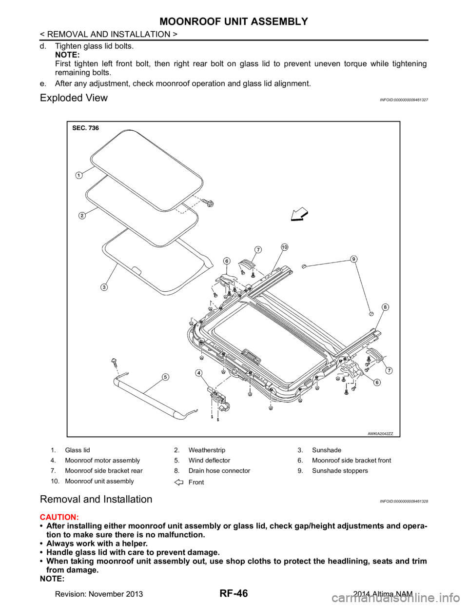
Exploded ViewINFOID:0000000009461327
Removal and InstallationINFOID:0000000009461328
CAUTION:
• After installing either moonro of unit assembly or glass lid, check gap/height adjustments and opera-
tion to make sure there is no malfunction.
• Always work with a helper.
• Handle glass lid with care to prevent damage.
• When taking moonroof unit assembly out, use shop cloths to protect the headlining, seats and trim
from damage.
NOTE:
1. Glass lid 2. Weatherstrip 3. Sunshade
4. Moonroof motor assembly 5. Wind deflector 6. Moonroof side bracket front
7. Moonroof side bracket rear 8. Drain hose connector 9. Sunshade stoppers
10. Moonroof unit assembly Front
AWKIA2042ZZ
Revision: November 20132014 Altima NAMRevision: November 20132014 Altima NAM
Page 3718 of 4801
RSU-1
SUSPENSION
C
D
F
G H
I
J
K L
M
SECTION RSU
A
B
RSU
N
O PCONTENTS
REAR SUSPENSION
PRECAUTION ................ ...............................2
PRECAUTIONS .............................................. .....2
Precaution for Supplemental Restraint System
(SRS) "AIR BAG" and "SEAT BELT PRE-TEN-
SIONER" ............................................................. ......
2
General Precautions .................................................2
PREPARATION ............................................3
PREPARATION .............................................. .....3
Commercial Service Tool .................................... ......3
SYMPTOM DIAGNOSIS ...............................4
NOISE, VIBRATION AND HARSHNESS
(NVH) TROUBLESHOOTING ........................ .....
4
NVH Troubleshooting Chart ................................ ......4
PERIODIC MAINTENANCE ..........................5
REAR SUSPENSION ASSEMBLY ................ .....5
On-vehicle Service .............................................. ......5
Inspection ..................................................................5
Inspection and Adjustment ........................................5
UNIT REMOVAL AND INSTALLATION .......8
REAR SUSPENSION ASSEMBLY ................ .....8
Exploded View .................................................... ......8
Removal and Installation ..................................... .....8
REMOVAL AND INSTALLATION ...............12
REAR LOWER LINK & COIL SPRING .............12
Removal and Installation ..................................... ....12
SHOCK ABSORBER ........................................13
Exploded View .........................................................13
Removal and Installation .........................................13
Disassembly and Assembly .....................................14
Disposal ...................................................................14
REAR STABILIZER ..........................................15
Exploded View .........................................................15
Removal and Installation .........................................15
SUSPENSION ARM ..........................................16
Exploded View .........................................................16
Removal and Installation .........................................16
SERVICE DATA AND SPECIFICATIONS
(SDS) ............... .............................................
17
SERVICE DATA AND SPECIFICATIONS
(SDS) .................................................................
17
General Specification (Rear) ............................... ....17
Wheel Alignment (Unladen*) ...................................17
Wheelarch Height (Unladen*1) ................................17
Revision: November 20132014 Altima NAM
Page 3722 of 4801
REAR SUSPENSION ASSEMBLYRSU-5
< PERIODIC MAINTENANCE >
C
D
F
G H
I
J
K L
M A
B
RSU
N
O P
PERIODIC MAINTENANCE
REAR SUSPENSION ASSEMBLY
On-vehicle ServiceINFOID:0000000009464454
• Check the suspension parts for excessive play, cracks, wear or damage. Shake each rear wheel to check for
excessive play.
• Retighten all nuts and bolts to the specified torque.
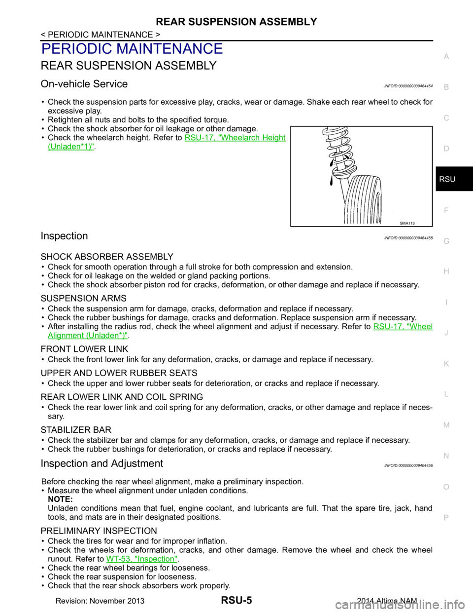
• Check the shock absorber for oil leakage or other damage.
• Check the wheelarch height. Refer to RSU-17, "Wheelarch Height
(Unladen*1)".
InspectionINFOID:0000000009464455
SHOCK ABSORBER ASSEMBLY
• Check for smooth operation through a full stroke for both compression and extension.
• Check for oil leakage on the welded or gland packing portions.
• Check the shock absorber piston r od for cracks, deformation, or other damage and replace if necessary.
SUSPENSION ARMS
• Check the suspension arm for damage, cracks, deformation and replace if necessary.
• Check the rubber bushings for damage, cracks and defo rmation. Replace suspension arm if necessary.
• After installing the radius rod, check the wheel alignment and adjust if necessary. Refer to RSU-17, "Wheel
Alignment (Unladen*)".
FRONT LOWER LINK
• Check the front lower link for any deformation, cracks, or damage and replace if necessary.
UPPER AND LOWER RUBBER SEATS
• Check the upper and lower rubber seats for deterioration, or cracks and replace if necessary.
REAR LOWER LINK AND COIL SPRING
• Check the rear lower link and coil spring for any def ormation, cracks, or other damage and replace if neces-
sary.
STABILIZER BAR
• Check the stabilizer bar and clamps for any deformation, cracks, or damage and replace if necessary.
• Check the rubber bushings for deterioration, or cracks and replace if necessary.
Inspection and AdjustmentINFOID:0000000009464456
Before checking the rear wheel ali gnment, make a preliminary inspection.
• Measure the wheel alignment under unladen conditions. NOTE:
Unladen conditions mean that fuel, engine coolant, and l ubricants are full. That the spare tire, jack, hand
tools, and mats are in their designated positions.
PRELIMINARY INSPECTION
• Check the tires for wear and for improper inflation.
• Check the wheels for deformation, cracks, and ot her damage. Remove the wheel and check the wheel
runout. Refer to WT-53, "Inspection"
.
• Check the rear wheel bearings for looseness.
• Check the rear suspension for looseness.
• Check that the rear shock absorbers work properly.
SMA113
Revision: November 20132014 Altima NAM
Page 3725 of 4801
RSU-8
< UNIT REMOVAL AND INSTALLATION >
REAR SUSPENSION ASSEMBLY
UNIT REMOVAL AND INSTALLATION
REAR SUSPENSION ASSEMBLY
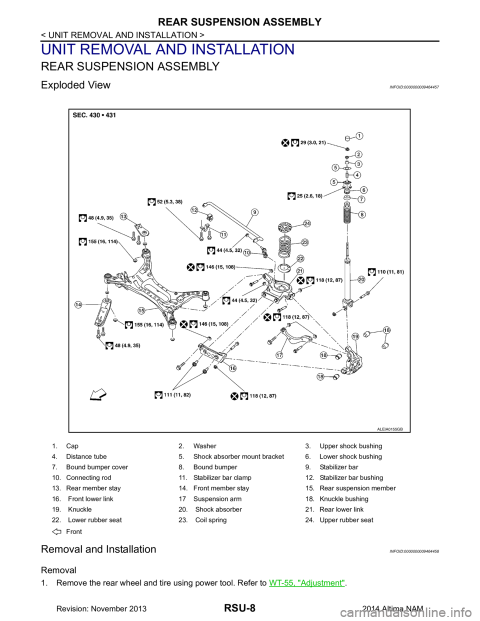
Exploded ViewINFOID:0000000009464457
Removal and InstallationINFOID:0000000009464458
Removal
1. Remove the rear wheel and tire using power tool. Refer to WT-55, "Adjustment".
1. Cap 2. Washer 3. Upper shock bushing
4. Distance tube 5. Shock absorber mount bracket 6. Lower shock bushing
7. Bound bumper cover 8. Bound bumper 9. Stabilizer bar
10. Connecting rod 11. Stabilizer bar clamp 12. Stabilizer bar bushing
13. Rear member stay 14. Front member stay 15. Rear suspension member
16. Front lower link 17 Suspension arm 18. Knuckle bushing
19. Knuckle 20. Shock absorber 21. Rear lower link
22. Lower rubber seat 23. Coil spring 24. Upper rubber seat
Front
ALEIA0155GB
Revision: November 20132014 Altima NAM