2014 NISSAN TEANA Pro pressure
[x] Cancel search: Pro pressurePage 3257 of 4801

MWI-2
Wiring Diagram .......................................................30
METER ...............................................................32
Wiring Diagram .................................................... ...32
BASIC INSPECTION ...................................51
DIAGNOSIS AND REPAIR WORKFLOW ...... ...51
Work flow ............................................................. ...51
DTC/CIRCUIT DIAGNOSIS ...................... ...53
U1000 CAN COMM CIRCUIT ......................... ...53
DTC Logic ............................................................ ...53
Diagnosis Procedure .............................................53
U1010 CONTROL UNIT (CAN) .........................54
Description ........................................................... ...54
DTC Logic ...............................................................54
Diagnosis Procedure ..............................................54
B2205 VEHICLE SPEED ...................................55
Description ........................................................... ...55
DTC Logic ...............................................................55
Diagnosis Procedure .............................................55
B2267 ENGINE SPEED .....................................56
Description ........................................................... ...56
DTC Logic ...............................................................56
Diagnosis Procedure ..............................................56
B2268 WATER TEMP ........................................57
Description ........................................................... ...57
DTC Logic ...............................................................57
Diagnosis Procedure ..............................................57
POWER SUPPLY AND GROUND CIRCUIT .....58
COMBINATION METER ........................................ ...58
COMBINATION METER : Diagnosis Procedure ....58
BCM (BODY CONTROL MODULE) ...................... ...58
BCM (BODY CONTROL MODULE) : Diagnosis
Procedure ............................................................ ...
58
IPDM E/R (INTELLIGENT POWER DISTRIBU-
TION MODULE ENGINE ROOM) .......................... ...
59
IPDM E/R (INTELLIGENT POWER DISTRIBU-
TION MODULE ENGINE ROOM) : Diagnosis Pro-
cedure .................................................................. ...
59
FUEL LEVEL SENSOR SIGNAL CIRCUIT .......61
Description ........................................................... ...61
Component Function Check ...................................61
Diagnosis Procedure .............................................61
Component Inspection ............................................62
PARKING BRAKE SWITCH SIGNAL CIR-
CUIT ................................................................ ...
63
Description ........................................................... ...63
Component Function Check ...................................63
Diagnosis Procedure ..............................................63
Component Inspection ......................................... ...63
WASHER FLUID LEVEL SWITCH CIRCUIT ....64
Description ........................................................... ...64
Diagnosis Procedure ...............................................64
Component Inspection ............................................64
AMBIENT SENSOR SIGNAL CIRCUIT ............66
Description ........................................................... ...66
Component Function Check ...................................66
Diagnosis Procedure ...............................................66
Component Inspection ............................................67
METER CONTROL SWITCH SIGNAL CIR-
CUIT ................................................................ ...
68
Diagnosis Procedure ............................................ ...68
Component Inspection ............................................69
STEERING SWITCH ..........................................70
Description ........................................................... ...70
Diagnosis Procedure ...............................................70
Component Inspection ............................................70
SYMPTOM DIAGNOSIS ............................72
THE FUEL GAUGE INDICATOR DOES NOT
OPERATE ....................................................... ...
72
Description ........................................................... ...72
Diagnosis Procedure ...............................................72
THE METER CONTROL SWITCH IS INOPER-
ATIVE .............................................................. ...
73
Description ........................................................... ...73
Diagnosis Procedure ...............................................73
THE OIL PRESSURE WARNING CONTIN-
UES DISPLAYING, OR DOES NOT DISPLAY ...
74
Description ........................................................... ...74
Diagnosis Procedure ...............................................74
THE PARKING BRAKE RELEASE WARNING
CONTINUES DISPLAYING, OR DOES NOT
DISPLAY ......................................................... ...
75
Description ........................................................... ...75
Diagnosis Procedure ...............................................75
THE LOW WASHER FLUID WARNING CON-
TINUES DISPLAYING, or DOES NOT DIS-
PLAY ............................................................... ...
76
Description ........................................................... ...76
Diagnosis Procedure ...............................................76
THE DOOR OPEN WARNING CONTINUES
DISPLAYING, OR DOES NOT DISPLAY ...... ...
77
Description ........................................................... ...77
Diagnosis Procedure ...............................................77
THE TRUNK OPEN WARNING CONTINUES
DISPLAYING, OR DOES NOT DISPLAY ...... ...
78
Description ........................................................... ...78
Diagnosis Procedure ...............................................78
Revision: November 20132014 Altima NAMRevision: November 20132014 Altima NAM
Page 3266 of 4801
MWI
SYSTEMMWI-11
< SYSTEM DESCRIPTION >
C
D E
F
G H
I
J
K L
M B
A
O P
SPEEDOMETER
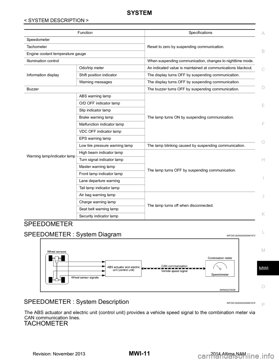
SPEEDOMETER : System DiagramINFOID:0000000009461675
SPEEDOMETER : System DescriptionINFOID:0000000009461676
The ABS actuator and electric unit (control unit) provi des a vehicle speed signal to the combination meter via
CAN communication lines.
TACHOMETER
Function Specifications
Speedometer Reset to zero by suspending communication.
Tachometer
Engine coolant temperature gauge
Illumination control When suspending communication, changes to nighttime mode.
Information display Odo/trip meter An indicated value is maintained at communications blackout.
Shift position indicator The display turns OFF by suspending communication.
Warning messages The display turns OFF by suspending communication.
Buzzer The buzzer turns OFF by suspending communication.
Warning lamp/indicator lamp ABS warning lamp
The lamp turns ON by suspending communication.
O/D OFF indicator lamp
Slip indicator lamp
Brake warning lamp
Malfunction indicator lamp
VDC OFF indicator lamp
EPS warning lamp
Low tire pressure warning lamp The lamp blinking caused by suspending communication.
High beam indicator lamp
The lamp turns OFF by suspending communication.
Turn signal indicator lamp
Master warning lamp
Front lamp indicator lamp
Lane departure warning
Tail lamp indicator lamp
Air bag warning lamp
The lamp turns off when disconnected.
Charge warning lamp
Seat belt warning lamp
Security indicator lamp
AWNIA2379GB
Revision: November 20132014 Altima NAMRevision: November 20132014 Altima NAM
Page 3271 of 4801

MWI-16
< SYSTEM DESCRIPTION >
SYSTEM
The LOOSE FUEL CAP message will display in the information display when the fuel-filler cap is not tightened
correctly. The message will turn off as soon as the EC M detects the fuel-filler cap is properly tightened. The
ECM provides a loose fuel cap signal to the combination meter via CAN communication.
LOW TIRE PRESSURE WARNING
This warning appears when the BCM detects low inflati on pressure or a system malfunction. The BCM sends
a signal to the combination meter via CAN communication to illuminate the low tire pressure warning lamp. In
addition, a warning message will be displayed in the vehicle information display.
DOOR OPEN WARNING
This warning appears when the ignition switch is ON and the door is open. The BCM receives a door switch
signal from the door open door switch. The BCM sends t he door switch signal to the combination meter via
CAN communication lines.
TRUNK OPEN WARNING
This warning appears when the ignition switch is ON and the trunk is opened. The BCM receives a trunk lamp
switch signal from the trunk lamp switch. The BCM s ends the trunk lamp switch signal to the combination
meter via CAN communication.
LOW FUEL WARNING
This warning appears when the fuel level in the fuel tank is less than approximately 4 US gal (15 L, 3.3 Imp
gal). A variable resistor signal is supplied to the combi nation meter from the fuel level sensor unit to determine
the amount of fuel in the fuel tank.
LOW WINDSHIELD WASHER FLUID WARNING
When the windshield washer fluid level is low, the was her fluid level switch provides a ground signal to the
combination meter and the warning is displayed. Once fluid is added, the switch opens and the warning is no
longer displayed.
RELEASE PARKING BRAKE WARNING
When the parking brake is applied, the parking brake switch provides a ground signal to the combination
meter. When the vehicle speed is greater than 4 MPH (7 km/h), the message is displayed and the warning
chime sounds.
SHIFT POSITION INDICATOR
Displays the position of the shift selector based on signals received from TCM via CAN communication.
LOW OIL PRESSURE WARNING
The low oil pressure warning appears in the information display when the combination meter receives a low
engine oil pressure signal from the ECM via CAN communication.
WARNING CHECK INDICATION
The combination meter can cause an interrupt on the information display to indicate a warning, based on sig-
nals received from each unit and switch.
Refer to Owner’s Manual for additional information display items.
COMPASS
COMPASS : DescriptionINFOID:0000000009461691
DESCRIPTION
With the ignition switch in the ON position, and the mode (N) switch
ON, the compass display will indicate the direction the vehicle is
heading.
Vehicle direction is displayed as follows:
• N: north
• E: east
• S: south
•W: west
LKIA0447E
Revision: November 20132014 Altima NAMRevision: November 20132014 Altima NAM
Page 3279 of 4801
MWI-24
< ECU DIAGNOSIS INFORMATION >
COMBINATION METER
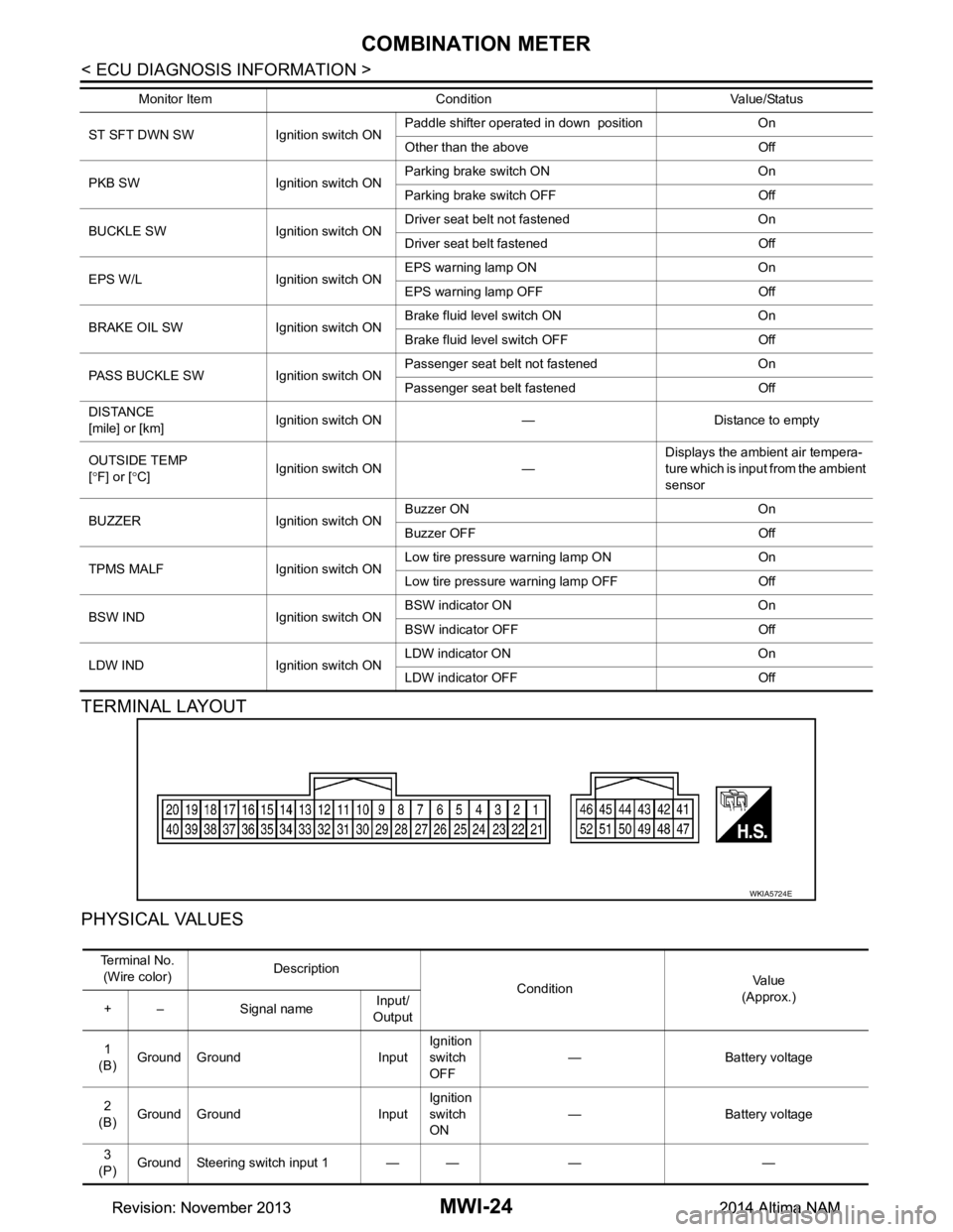
TERMINAL LAYOUT
PHYSICAL VALUES
ST SFT DWN SW Ignition switch ON Paddle shifter operated in down position On
Other than the above Off
PKB SW Ignition switch ON Parking brake switch ON On
Parking brake switch OFF Off
BUCKLE SW Ignition switch ON Driver seat belt not fastened On
Driver seat belt fastened Off
EPS W/L Ignition switch ON EPS warning lamp ON On
EPS warning lamp OFF Off
BRAKE OIL SW Ignition switch ON Brake fluid level switch ON On
Brake fluid level switch OFF Off
PASS BUCKLE SW Ignition switch ON Passenger seat belt not fastened On
Passenger seat belt fastened Off
DISTANCE
[mile] or [km] Ignition switch ON — Distance to empty
OUTSIDE TEMP
[ ° F] or [ °C] Ignition switch ON — Displays the ambient air tempera-
ture which is input from the ambient
sensor
BUZZER Ignition switch ON Buzzer ON On
Buzzer OFF Off
TPMS MALF Ignition switch ON Low tire pressure
warning lamp ON On
Low tire pressure warning lamp OFF Off
BSW IND Ignition switch ON BSW indicator ON On
BSW indicator OFF Off
LDW IND Ignition switch ON LDW indicator ON On
LDW indicator OFF Off
Monitor Item Condition Value/Status
WKIA5724E
Te r m i n a l N o .
(Wire color) Description
ConditionVa l u e
(Approx.)
+ – Signal name Input/
Output
1
(B) Ground Ground Input Ignition
switch
OFF — Battery voltage
2
(B) Ground Ground Input Ignition
switch
ON — Battery voltage
3
(P) Ground Steering switch input 1 — — — —
Revision: November 20132014 Altima NAMRevision: November 20132014 Altima NAM
Page 3282 of 4801

MWI
COMBINATION METERMWI-27
< ECU DIAGNOSIS INFORMATION >
C
D E
F
G H
I
J
K L
M B
A
O PFail-SafeINFOID:0000000009461695
FA I L - S A F E
The combination meter activates the fail-safe contro l if CAN communication with each unit is malfunctioning.
DTC IndexINFOID:0000000009461696
52
(P) Ground O/D OFF/SPORT switch Input Ignition
switch
ON O/D OFF switch pressed 0 V
Other than the above 5 V
Te r m i n a l N o .
(Wire color) Description
ConditionVa l u e
(Approx.)
+ – Signal name Input/
Output
Function Specifications
Speedometer Reset to zero by suspending communication.
Tachometer
Engine coolant temperature gauge
Illumination control When suspending communication, changes to nighttime mode.
Information display Odo/trip meter An indicated value is maintained at communications blackout.
Shift position indicator The display turns OFF by suspending communication.
Warning messages The display turns OFF by suspending communication.
Buzzer The buzzer turns OFF by suspending communication.
Warning lamp/indicator lamp ABS warning lamp
The lamp turns ON by suspending communication.
O/D OFF indicator lamp
Slip indicator lamp
Brake warning lamp
Malfunction indicator lamp
VDC OFF indicator lamp
EPS warning lamp
Low tire pressure warning lamp The lamp blinking caused by suspending communication.
High beam indicator lamp
The lamp turns OFF by suspending communication.
Turn signal indicator lamp
Master warning lamp
Front lamp indicator lamp
Lane departure warning
Tail lamp indicator lamp
Air bag warning lamp
The lamp turns off when disconnected.
Charge warning lamp
Seat belt warning lamp
Security indicator lamp
Display contents of CONSULT Diagnostic item is detected when... Refer to
CAN COMM CIRCUIT
[U1000] When combination meter is not transmitting or receiving CAN communication signal for 2
seconds or more. MWI-53
CONTROL UNIT (CAN)
[U1010] When detecting error during the initial diagnosis of the CAN controller of combination
meter. MWI-54
Revision: November 20132014 Altima NAMRevision: November 20132014 Altima NAM
Page 3329 of 4801
MWI-74
< SYMPTOM DIAGNOSIS >
THE OIL PRESSURE WARNING CONTINUES DISPLAYING, OR DOES NOT DIS-
PLAY
THE OIL PRESSURE WARNING CONT INUES DISPLAYING, OR DOES
NOT DISPLAY
DescriptionINFOID:0000000009461742
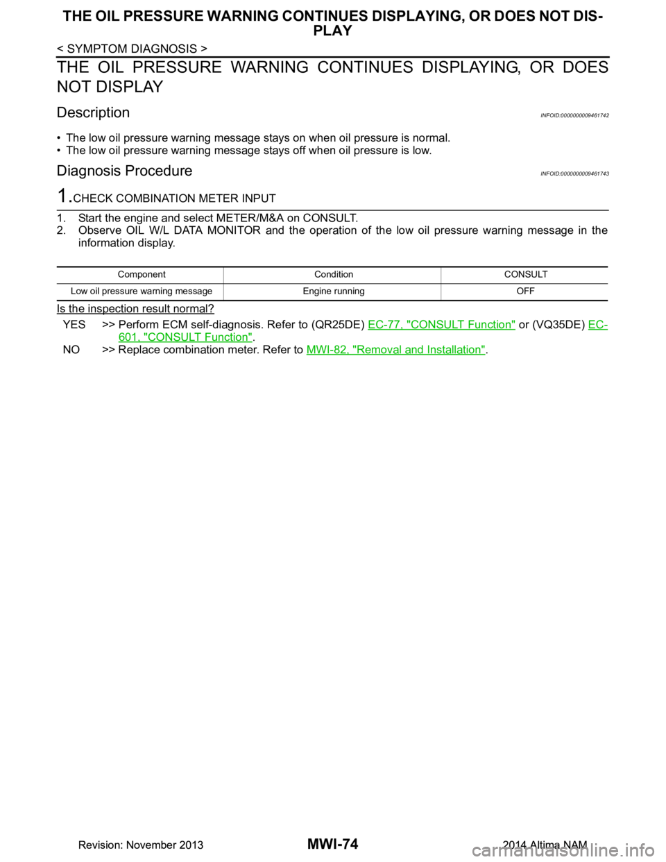
• The low oil pressure warning message stays on when oil pressure is normal.
• The low oil pressure warning message stays off when oil pressure is low.
Diagnosis ProcedureINFOID:0000000009461743
1.CHECK COMBINATION METER INPUT
1. Start the engine and select METER/M&A on CONSULT.
2. Observe OIL W/L DATA MONITOR and the operation of the low oil pressure warning message in the
information display.
Is the inspection result normal?
YES >> Perform ECM self-diagnosis. Refer to (QR25DE) EC-77, "CONSULT Function" or (VQ35DE) EC-
601, "CONSULT Function".
NO >> Replace combination meter. Refer to MWI-82, "Removal and Installation"
.
Component Condi tion CONSULT
Low oil pressure warning message Engine running OFF
Revision: November 20132014 Altima NAMRevision: November 20132014 Altima NAM
Page 3968 of 4801
SR-6
< BASIC INSPECTION >
COLLISION DIAGNOSIS
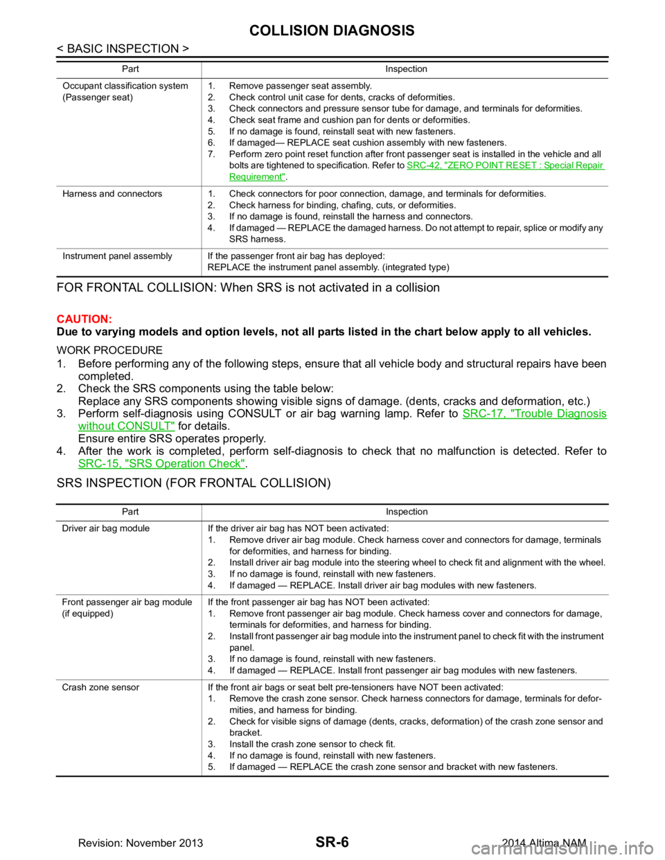
FOR FRONTAL COLLISION: When SRS is not activated in a collision
CAUTION:
Due to varying models and option levels, not all part s listed in the chart below apply to all vehicles.
WORK PROCEDURE
1. Before performing any of the following steps, ensur e that all vehicle body and structural repairs have been
completed.
2. Check the SRS components using the table below:
Replace any SRS components showing visible signs of damage. (dents, cracks and deformation, etc.)
3. Perform self-diagnosis using CONSULT or air bag warning lamp. Refer to SRC-17, "Trouble Diagnosis
without CONSULT" for details.
Ensure entire SRS operates properly.
4. After the work is completed, perform self-diagnosis to check that no malfunction is detected. Refer to
SRC-15, "SRS Operation Check"
.
SRS INSPECTION (FOR FRONTAL COLLISION)
Occupant classification system
(Passenger seat) 1. Remove passenger seat assembly.
2. Check control unit case for dents, cracks of deformities.
3. Check connectors and pressure sensor tube for damage, and terminals for deformities.
4. Check seat frame and cushion pan for dents or deformities.
5. If no damage is found, reinstall seat with new fasteners.
6. If damaged— REPLACE seat cushion assembly with new fasteners.
7. Perform zero point reset function after front passenger seat is installed in the vehicle and all bolts are tightened to specification. Refer to SRC-42, "ZERO POINT RESET : Special Repair
Requirement".
Harness and connectors 1. Check connectors for poor connection, damage, and terminals for deformities. 2. Check harness for binding, chafing, cuts, or deformities.
3. If no damage is found, reinstall the harness and connectors.
4. If damaged — REPLACE the damaged harness. Do not attempt to repair, splice or modify any SRS harness.
Instrument panel assembly If the passenger front air bag has deployed: REPLACE the instrument panel assembly. (integrated type)
Part Inspection
Part Inspection
Driver air bag module If the driver air bag has NOT been activated: 1. Remove driver air bag module. Check harness cover and connectors for damage, terminals for deformities, and harness for binding.
2. Install driver air bag module into the steering wheel to check fit and alignment with the wheel.
3. If no damage is found, reinstall with new fasteners.
4. If damaged — REPLACE. Install driver air bag modules with new fasteners.
Front passenger air bag module
(if equipped) If the front passenger air bag has NOT been activated:
1. Remove front passenger air bag module. Check harness cover and connectors for damage, terminals for deformities, and harness for binding.
2. Install front passenger air bag module into the instrument panel to check fit with the instrument panel.
3. If no damage is found, reinstall with new fasteners.
4. If damaged — REPLACE. Install front passenger air bag modules with new fasteners.
Crash zone sensor If the front air bags or seat belt pre-tensioners have NOT been activated: 1. Remove the crash zone sensor. Check harness connectors for damage, terminals for defor-mities, and harness for binding.
2. Check for visible signs of damage (dents, cracks, deformation) of the crash zone sensor and bracket.
3. Install the crash zone sensor to check fit.
4. If no damage is found, reinstall with new fasteners.
5. If damaged — REPLACE the crash zone sensor and bracket with new fasteners.
Revision: November 20132014 Altima NAM
Page 3969 of 4801
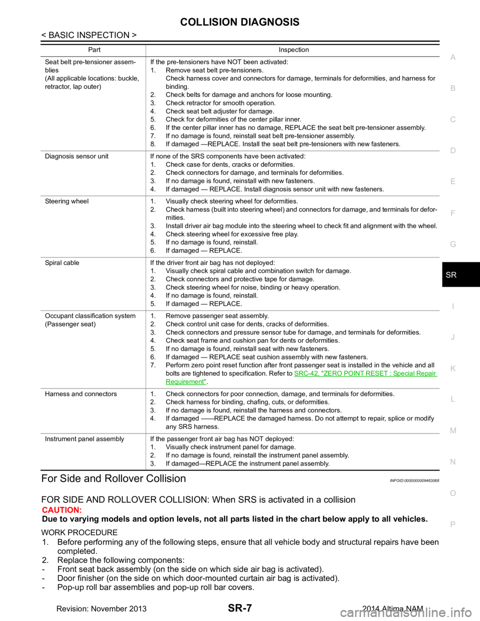
COLLISION DIAGNOSISSR-7
< BASIC INSPECTION >
C
D E
F
G
I
J
K L
M A
B
SR
N
O P
For Side and Rollover CollisionINFOID:0000000009463068
FOR SIDE AND ROLLOVER COLLISION: When SRS is activated in a collision
CAUTION:
Due to varying models and option levels, not all parts listed in the chart below apply to all vehicles.
WORK PROCEDURE
1. Before performing any of the following steps, ensur e that all vehicle body and structural repairs have been
completed.
2. Replace the following components:
- Front seat back assembly (on the side on which side air bag is activated).
- Door finisher (on the side on which door-mounted curtain air bag is activated).
- Pop-up roll bar assemblies and pop-up roll bar covers.
Seat belt pre-tensioner assem-
blies
(All applicable locations: buckle,
retractor, lap outer) If the pre-tensioners have NOT been activated:
1. Remove seat belt pre-tensioners.
Check harness cover and connectors for damage, terminals for deformities, and harness for
binding.
2. Check belts for damage and anchors for loose mounting.
3. Check retractor for smooth operation.
4. Check seat belt adjuster for damage.
5. Check for deformities of the center pillar inner.
6. If the center pillar inner has no damage, REPLACE the seat belt pre-tensioner assembly.
7. If no damage is found, reinstall seat belt pre-tensioner assembly.
8. If damaged —REPLACE. Install the seat belt pre-tensioners with new fasteners.
Diagnosis sensor unit If none of the SRS components have been activated: 1. Check case for dents, cracks or deformities.
2. Check connectors for damage, and terminals for deformities.
3. If no damage is found, reinstall with new fasteners.
4. If damaged — REPLACE. Install diagnosis sensor unit with new fasteners.
Steering wheel 1. Visually check steering wheel for deformities. 2. Check harness (built into steering wheel) and connectors for damage, and terminals for defor-mities.
3. Install driver air bag module into the steering wheel to check fit and alignment with the wheel.
4. Check steering wheel for excessive free play.
5. If no damage is found, reinstall.
6. If damaged — REPLACE.
Spiral cable If the driver front air bag has not deployed: 1. Visually check spiral cable and combination switch for damage.
2. Check connectors and protective tape for damage.
3. Check steering wheel for noise, binding or heavy operation.
4. If no damage is found, reinstall.
5. If damaged — REPLACE.
Occupant classification system
(Passenger seat) 1. Remove passenger seat assembly.
2. Check control unit case for dents, cracks of deformities.
3. Check connectors and pressure sensor tube for damage, and terminals for deformities.
4. Check seat frame and cushion pan for dents or deformities.
5. If no damage is found, reinstall seat with new fasteners.
6. If damaged — REPLACE seat cushion assembly with new fasteners.
7. Perform zero point reset function after front passenger seat is installed in the vehicle and all
bolts are tightened to specification. Refer to SRC-42, "ZERO POINT RESET : Special Repair
Requirement".
Harness and connectors 1. Check connectors for poor connection, damage, and terminals for deformities. 2. Check harness for binding, chafing, cuts, or deformities.
3. If no damage is found, reinstall the harness and connectors.
4. If damaged ——REPLACE the damaged harness. Do not attempt to repair, splice or modify any SRS harness.
Instrument panel assembly If the passenger front air bag has NOT deployed: 1. Visually check instrument panel for damage.
2. If no damage is found, reinstall the instrument panel assembly.
3. If damaged—REPLACE the instrument panel assembly.
Part Inspection
Revision: November 20132014 Altima NAM