Page 2737 of 4801
![NISSAN TEANA 2014 Service Manual
HAC-88
< DTC/CIRCUIT DIAGNOSIS >[AUTOMATIC AIR CONDITIONER]
A/C SWITCH ASSEMBLY SIGNAL CIRCUIT
A/C SWITCH ASSEMBL
Y SIGNAL CIRCUIT
Diagnosis ProcedureINFOID:0000000009463161
Regarding Wiring Diagram](/manual-img/5/57390/w960_57390-2736.png "NISSAN TEANA 2014 Service Manual
HAC-88
< DTC/CIRCUIT DIAGNOSIS >[AUTOMATIC AIR CONDITIONER]
A/C SWITCH ASSEMBLY SIGNAL CIRCUIT
A/C SWITCH ASSEMBL
Y SIGNAL CIRCUIT
Diagnosis ProcedureINFOID:0000000009463161
Regarding Wiring Diagram")
HAC-88
< DTC/CIRCUIT DIAGNOSIS >[AUTOMATIC AIR CONDITIONER]
A/C SWITCH ASSEMBLY SIGNAL CIRCUIT
A/C SWITCH ASSEMBL
Y SIGNAL CIRCUIT
Diagnosis ProcedureINFOID:0000000009463161
Regarding Wiring Diagram information, refer to HAC-34, "Wiring Diagram".
1.CHECK WITH SELF-DIAGNOSIS FUNCTION OF CONSULT
1. Using CONSULT, perform “SELF- DIAGNOSIS RESULTS” of HVAC.
2. Check if any DTC No. is displayed in the self-diagnosis results.
NOTE:
If DTC is displayed along with DTC U1000 or U1010, first diagnose the DTC U1000 or U1010. Refer to HAC-
55, "DTC Logic" or HAC-56, "DTC Logic".
Is any DTC No. displayed?
YES >> Perform diagnosis for the applicable DTC. Refer to HAC-31, "DTC Index".
NO >> GO TO 2.
2.CHECK TX (A/C SWITCH ASSEMBLY → A/C AUTO AMP.) CIRCUIT CONTINUITY
1. Turn ignition switch OFF.
2. Disconnect the A/C switch assembly and the A/C auto amp. connectors.
3. Check continuity between A/C switch assembly harness connector M79 terminal 10 and A/C auto amp.
harness connector M152 terminal 24.
4. Check continuity between A/C switch assembly harness connector M79 terminal 10 and ground.
Is the inspection result normal?
YES >> GO TO 3.
NO >> Repair harness or connector.
3.CHECK RX (A/C AUTO AMP. → A/C SWITCH ASSEMBLY) CIRCUIT CONTINUITY
1. Check continuity between A/C switch assembly harness connector M79 terminal 9 and A/C auto amp. harness connector M152 terminal 4.
2. Check continuity between A/C switch assembly harness connector M79 terminal 9 and ground.
Is the inspection result normal?
YES >> Perform trouble diagnosis for the A/C switch assembly. Refer to HAC-83, "A/C SWITCH ASSEM-
BLY : Diagnosis Procedure".
NO >> Repair harness or connector.
A/C switch assembly A/C auto amp. Continuity
Connector Terminal Connector Terminal
M79 10 M152 24 Yes
A/C switch assembly —Continuity
Connector Terminal
M79 10 Ground No
A/C switch assembly A/C auto amp. Continuity
Connector Terminal Connector Terminal
M79 9 M152 4 Yes
A/C switch assembly —Continuity
Connector Terminal
M79 9 Ground No
Revision: November 20132014 Altima NAMRevision: November 20132014 Altima NAM
Page 2738 of 4801
![NISSAN TEANA 2014 Service Manual
DOOR MOTORHAC-89
< DTC/CIRCUIT DIAGNOSIS > [AUTOMATIC AIR CONDITIONER]
C
D E
F
G H
J
K L
M A
B
HAC
N
O P
DOOR MOTOR
Diagnosis ProcedureINFOID:0000000009463162
Regarding Wiring Diagram information,](/manual-img/5/57390/w960_57390-2737.png "NISSAN TEANA 2014 Service Manual
DOOR MOTORHAC-89
< DTC/CIRCUIT DIAGNOSIS > [AUTOMATIC AIR CONDITIONER]
C
D E
F
G H
J
K L
M A
B
HAC
N
O P
DOOR MOTOR
Diagnosis ProcedureINFOID:0000000009463162
Regarding Wiring Diagram information,")
DOOR MOTORHAC-89
< DTC/CIRCUIT DIAGNOSIS > [AUTOMATIC AIR CONDITIONER]
C
D E
F
G H
J
K L
M A
B
HAC
N
O P
DOOR MOTOR
Diagnosis ProcedureINFOID:0000000009463162
Regarding Wiring Diagram information, refer to HAC-34, "Wiring Diagram".
1.CHECK EACH DOOR MOTOR POWER SUPPLY
1. Turn ignition switch ON.
2. Check voltage between intake door motor harness connector and ground.
Is the inspection result normal?
YES >> GO TO 2.
NO >> GO TO 3.
2.CHECK EACH DOOR MOTOR GROUND CIRCUIT
1. Turn ignition switch OFF.
2. Disconnect intake door motor connector.
3. Check continuity between intake door motor harness connector and ground.
Is the inspection result normal?
YES >> Inspection End.
NO >> Repair harness or connector.
3.CHECK EACH DOOR MOTOR POWER SUPPLY CIRCUIT FOR OPEN
1. Disconnect A/C auto amp. connector.
2. Check continuity between intake door motor harness connector and A/C auto amp. harness connector.
Is the inspection result normal?
YES >> GO TO 4.
NO >> Repair harness or connector.
4.CHECK EACH DOOR MOTOR POWER SUPPLY CIRCUIT FOR SHORT
1. Disconnect following connectors.
- Air mix door motor LH
- Air mix door motor RH
- Mode door motor
2. Check continuity between intake door motor harness connector and ground.
+
−Voltag e
(Approx.)
Intake door motor
Connector Terminal M126 1 Ground Battery voltage
Intake door motor —Continuity
Connector Terminal
M126 2 Ground Yes
Intake door motor A/C auto amp. Continuity
Connector Terminal Connector Terminal
M126 1 M152 17 Yes
Intake door motor —Continuity
Connector Terminal
M126 1 Ground No
Revision: November 20132014 Altima NAMRevision: November 20132014 Altima NAM
Page 2740 of 4801
![NISSAN TEANA 2014 Service Manual
DOOR MOTOR COMMUNICATION CIRCUITHAC-91
< DTC/CIRCUIT DIAGNOSIS > [AUTOMATIC AIR CONDITIONER]
C
D E
F
G H
J
K L
M A
B
HAC
N
O P
DOOR MOTOR COMMUNI CATION CIRCUIT
Diagnosis ProcedureINFOID:0000000009](/manual-img/5/57390/w960_57390-2739.png "NISSAN TEANA 2014 Service Manual
DOOR MOTOR COMMUNICATION CIRCUITHAC-91
< DTC/CIRCUIT DIAGNOSIS > [AUTOMATIC AIR CONDITIONER]
C
D E
F
G H
J
K L
M A
B
HAC
N
O P
DOOR MOTOR COMMUNI CATION CIRCUIT
Diagnosis ProcedureINFOID:0000000009")
DOOR MOTOR COMMUNICATION CIRCUITHAC-91
< DTC/CIRCUIT DIAGNOSIS > [AUTOMATIC AIR CONDITIONER]
C
D E
F
G H
J
K L
M A
B
HAC
N
O P
DOOR MOTOR COMMUNI CATION CIRCUIT
Diagnosis ProcedureINFOID:0000000009463163
Regarding Wiring Diagram information, refer to HAC-34, "Wiring Diagram".
NOTE:
If all door motor DTCs are detected, check this circuit.
1.CHECK EACH DOOR MOTOR COMMUNICATION SIGNAL
1. Turn ignition switch ON.
2. Check output waveform between A/C auto amp. harness connector and ground with the oscilloscope.
Is the inspection result normal?
YES >> GO TO 2.
NO >> GO TO 3.
2.CHECK EACH DOOR MOTOR COMMUNICA TION SIGNAL CIRCUIT FOR OPEN
1. Turn ignition switch OFF.
2. Disconnect A/C auto amp. connector and intake door motor connector.
3. Check continuity between A/C auto amp. harness connector and intake door motor harness connector.
Is the inspection result normal?
YES >> Inspection End.
NO >> Repair harness or connector.
3.CHECK EACH DOOR MOTOR COMMUNICATION SIGNAL CIRCUIT FOR SHORT
1. Disconnect following connectors.
- Air mix door motor LH
- Air mix door motor RH
- Mode door motor
2. Check continuity between A/C aut o amp. harness connector and ground.
Is the inspection result normal?
YES >> Replace A/C auto amp. Refer to HAC-102, "Removal and Installation".
NO >> Repair harness or connector.
+
−Output waveform
A/C auto amp.
Connector Terminal
M152 16 Ground
SJIA1453J
A/C auto amp. Intake door motor Continuity
Connector Terminal Connector Terminal
M152 16 M126 3 Yes
A/C auto amp. —Continuity
Connector Terminal
M152 16 Ground No
Revision: November 20132014 Altima NAMRevision: November 20132014 Altima NAM
Page 4124 of 4801
POWER SUPPLY AND GROUND CIRCUITST-21
< DTC/CIRCUIT DIAGNOSIS >
C
D E
F
H I
J
K L
M A
B
ST
N
O P
DTC/CIRCUIT DIAGNOSIS
POWER SUPPLY AND GROUND CIRCUIT
A/C AUTO AMP.
A/C AUTO AMP. : Diagnosis ProcedureINFOID:0000000009952472
Regarding Wiring Diagram information, refer to HAC-34, "Wiring Diagram".
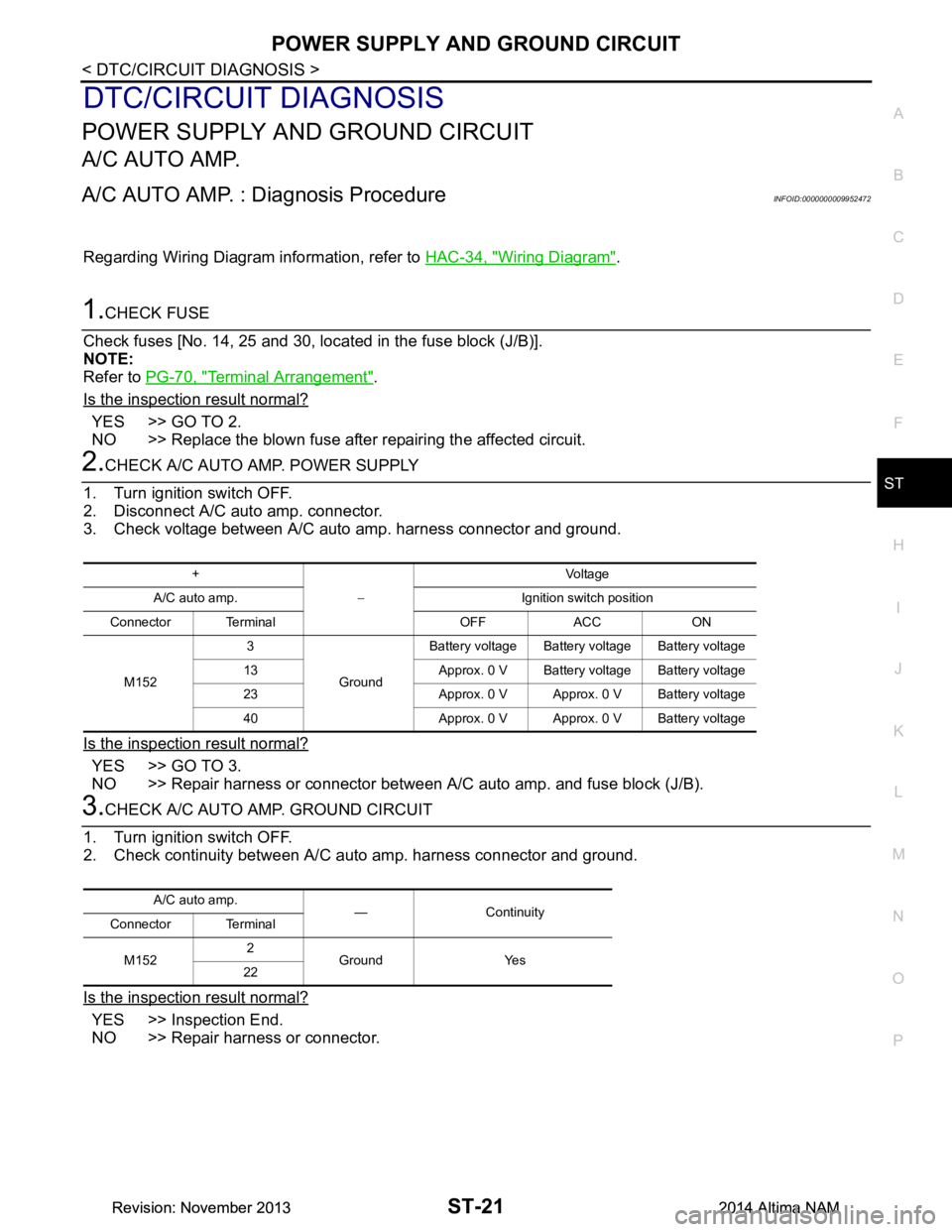
1.CHECK FUSE
Check fuses [No. 14, 25 and 30, loca ted in the fuse block (J/B)].
NOTE:
Refer to PG-70, "Terminal Arrangement"
.
Is the inspection result normal?
YES >> GO TO 2.
NO >> Replace the blown fuse after repairing the affected circuit.
2.CHECK A/C AUTO AMP. POWER SUPPLY
1. Turn ignition switch OFF.
2. Disconnect A/C auto amp. connector.
3. Check voltage between A/C auto amp. harness connector and ground.
Is the inspection result normal?
YES >> GO TO 3.
NO >> Repair harness or connector between A/C auto amp. and fuse block (J/B).
3.CHECK A/C AUTO AMP. GROUND CIRCUIT
1. Turn ignition switch OFF.
2. Check continuity between A/C aut o amp. harness connector and ground.
Is the inspection result normal?
YES >> Inspection End.
NO >> Repair harness or connector.
+
− Voltag e
A/C auto amp. Ignition switch position
Connector Terminal OFF ACC ON
M152 3
GroundBattery voltage Battery voltage Battery voltage
13 Approx. 0 V Battery voltage Battery voltage
23 Approx. 0 V Approx. 0 V Battery voltage
40 Approx. 0 V Approx. 0 V Battery voltage
A/C auto amp. — Continuity
Connector Terminal
M152 2
Ground Yes
22
Revision: November 20132014 Altima NAMRevision: November 20132014 Altima NAM
Page:
< prev 1-8 9-16 17-24