2014 NISSAN TEANA battery
[x] Cancel search: batteryPage 913 of 4801

REMOTE KEYLESS ENTRY RECEIVERDLK-145
< DTC/CIRCUIT DIAGNOSIS >
C
D E
F
G H
I
J
L
M A
B
DLK
N
O P
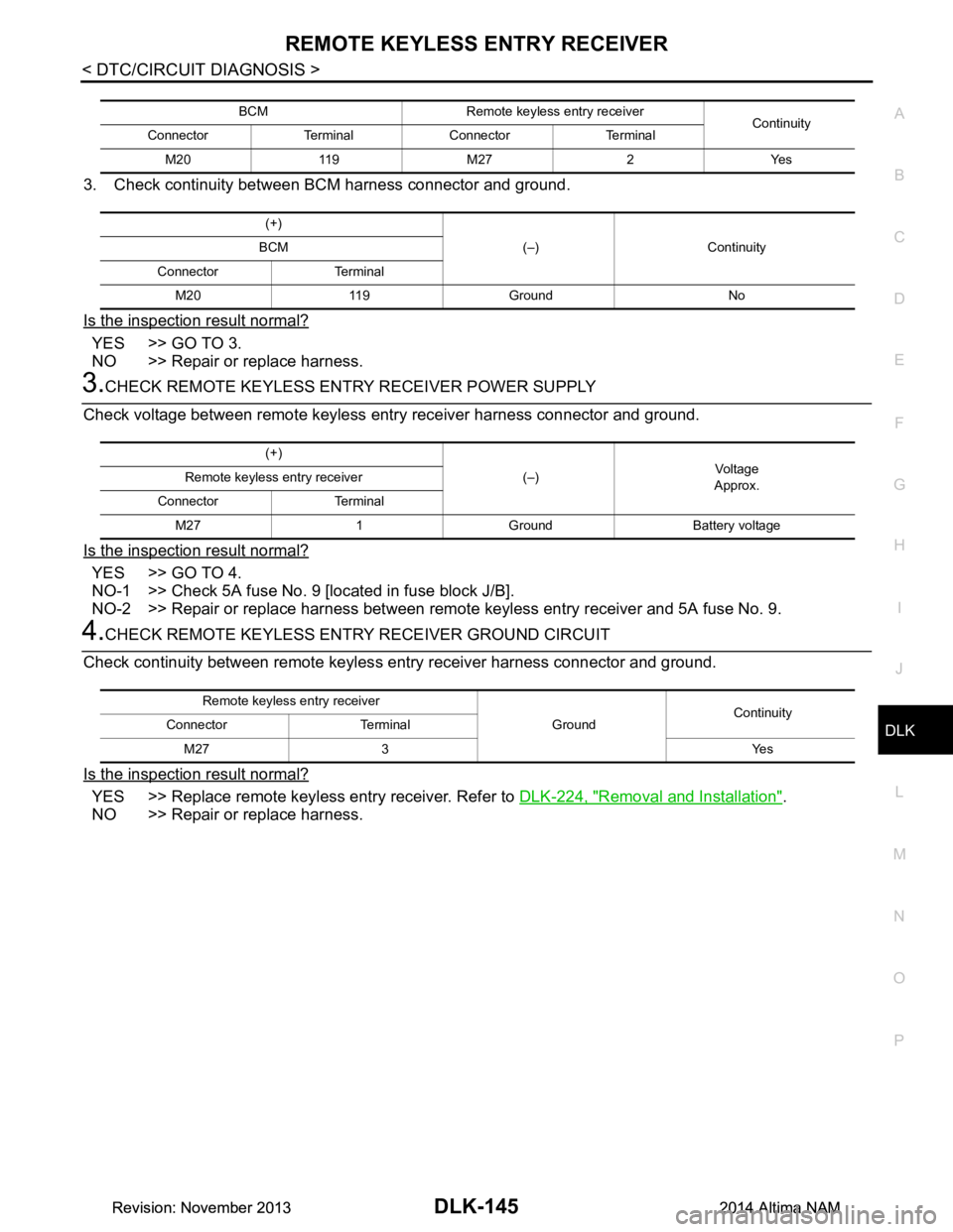
3. Check continuity between BCM harness connector and ground.
Is the inspection result normal?
YES >> GO TO 3.
NO >> Repair or replace harness.
3.CHECK REMOTE KEYLESS ENTRY RECEIVER POWER SUPPLY
Check voltage between remote keyless entry receiver harness connector and ground.
Is the inspection result normal?
YES >> GO TO 4.
NO-1 >> Check 5A fuse No. 9 [located in fuse block J/B].
NO-2 >> Repair or replace harness between remote keyless entry receiver and 5A fuse No. 9.
4.CHECK REMOTE KEYLESS ENTR Y RECEIVER GROUND CIRCUIT
Check continuity between remote keyles s entry receiver harness connector and ground.
Is the inspection result normal?
YES >> Replace remote keyless entry receiver. Refer to DLK-224, "Removal and Installation".
NO >> Repair or replace harness.
BCM Remote keyless entry receiver Continuity
Connector Terminal Connector Terminal
M20 119 M27 2 Yes
(+) (–) Continuity
BCM
Connector Terminal M20 119 Ground No
(+) (–)Vo l ta g e
Approx.
Remote keyless entry receiver
Connector Terminal M27 1 Ground Battery voltage
Remote keyless entry receiver GroundContinuity
Connector Terminal
M27 3 Yes
Revision: November 20132014 Altima NAMRevision: November 20132014 Altima NAM
Page 914 of 4801

DLK-146
< DTC/CIRCUIT DIAGNOSIS >
INTELLIGENT KEY BATTERY AND FUNCTION
INTELLIGENT KEY BATTERY AND FUNCTION
DescriptionINFOID:0000000009461895
The following functions are available when having and carrying the Intelligent Key.
• Door lock/unlock
• Trunk open
Remote control entry function and panic alarm functi on are available when operating the remote buttons.
Component Function CheckINFOID:0000000009461896
NOTE:
The Signal Tech II Tool (J-50190) can be used to perform the following functions. Refer to the Signal Tech II
User Guide for additional information.
• Check Intelligent Key relative signal strength
• Confirm vehicle Intelligent Key antenna signal strength
1.CHECK FUNCTION
With CONSULT
Check remote keyless entry receiver RKE OP E COUN1 in Data Monitor mode with CONSULT.
Is the inspection result normal?
YES >> Intelligent Key is OK.
NO >> Refer to DLK-146, "Diagnosis Procedure"
.
Diagnosis ProcedureINFOID:0000000009461897
NOTE:
The Signal Tech II Tool (J-50190) can be used to perform the following functions. Refer to the Signal Tech II
User Guide for additional information.
• Check Intelligent Key relative signal strength
• Confirm vehicle Intelligent Key antenna signal strength
1.CHECK INTELLIGENT KEY FUNCTION
Check Intelligent Key function using Signal Tech II Tool J-50190 or
Remote Keyless Entry Tester J-43241 (shown).
Does the test pass?
YES >> Intelligent Key is OK.
NO >> GO TO 2
2. CHECK INTELLIGENT KEY COMPONENTS
1. Release the lock knob at the back of the In telligent Key and remove the mechanical key.
Monitor item Condition
RKE OPE COUN1 Check that the numerical value is changing while operating with the Intelligent Key.
LEL946A
Revision: November 20132014 Altima NAMRevision: November 20132014 Altima NAM
Page 915 of 4801

INTELLIGENT KEY BATTERY AND FUNCTIONDLK-147
< DTC/CIRCUIT DIAGNOSIS >
C
D E
F
G H
I
J
L
M A
B
DLK
N
O P
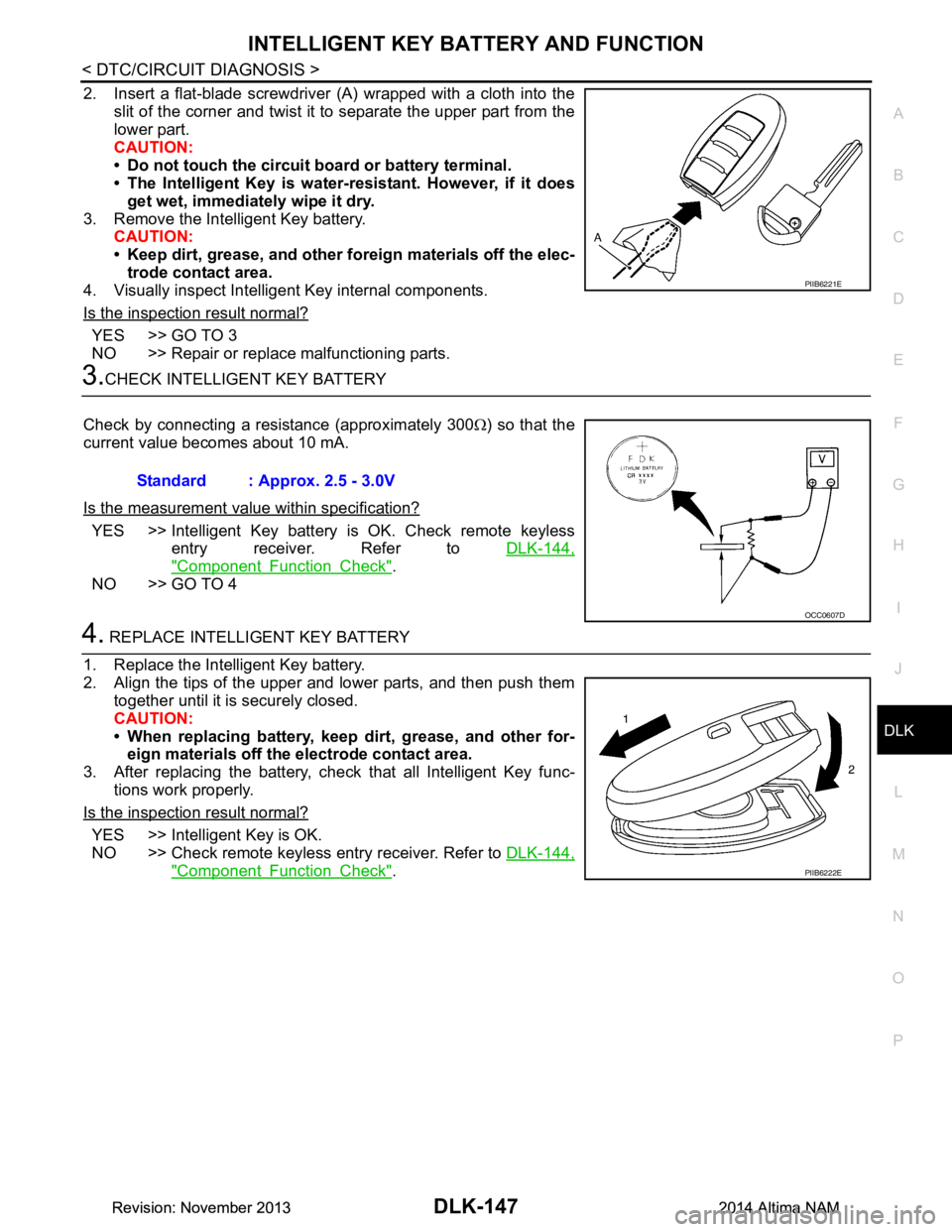
2. Insert a flat-blade screwdriver (A) wrapped with a cloth into the slit of the corner and twist it to separate the upper part from the
lower part.
CAUTION:
• Do not touch the circuit board or battery terminal.
• The Intelligent Key is water- resistant. However, if it does
get wet, immediately wipe it dry.
3. Remove the Intelligent Key battery. CAUTION:
• Keep dirt, grease, and other fo reign materials off the elec-
trode contact area.
4. Visually inspect Intelligent Key internal components.
Is the inspection result normal?
YES >> GO TO 3
NO >> Repair or replace malfunctioning parts.
3.CHECK INTELLIGENT KEY BATTERY
Check by connecting a resistance (approximately 300 Ω) so that the
current value becomes about 10 mA.
Is the measurement val ue within specification?
YES >> Intelligent Key battery is OK. Check remote keyless
entry receiver. Refer to DLK-144,
"Component Function Check".
NO >> GO TO 4
4. REPLACE INTELLIGENT KEY BATTERY
1. Replace the Intelligent Key battery.
2. Align the tips of the upper and lower parts, and then push them together until it is securely closed.
CAUTION:
• When replacing battery, keep dirt, grease, and other for- eign materials off the electrode contact area.
3. After replacing the battery, check that all Intelligent Key func-
tions work properly.
Is the inspection result normal?
YES >> Intelligent Key is OK.
NO >> Check remote keyless entry receiver. Refer to DLK-144,
"Component Function Check".
PIIB6221E
Standard : Approx. 2.5 - 3.0V
OCC0607D
PIIB6222E
Revision: November 20132014 Altima NAMRevision: November 20132014 Altima NAM
Page 918 of 4801

DLK-150
< DTC/CIRCUIT DIAGNOSIS >
HOMELINK UNIVERSAL TRANSCEIVER
HOMELINK UNIVERSAL TRANSCEIVER
DescriptionINFOID:0000000009461904
Homelink universal transceiver can store and transmit a maximum of 3 radio signals.
Allows operation of garage doors, gates, home and office lighting, entry door locks and security system, etc.
Homelink universal transceiver power supply uses vehicl e battery, which enables it to maintain every program
in case battery is discharged or removed.
Component Function CheckINFOID:0000000009461905
1.CHECK FUNCTION
Check that system receiver (garage door opener, et c.) operates with original hand-held transmitter.
Is the inspection result normal?
YES >> GO TO 2
NO >> Receiver or hand-held transmitter is malfunctioning.
2.CHECK ILLUMINATE
1. Turn ignition switch “OFF”.
2. Press each of the transmitter buttons and watch for the red light to illuminate with each button.
Is the inspection result normal?
YES >> GO TO 3
NO >> Refer to DLK-150, "Diagnosis Procedure"
.
3.CHECK TRANSMITTER
Check transmitter with Tool*.
*:For details, refer to Technical Service Bulletin.
Is the inspection result normal?
YES >> Receiver or hand-held transmitter malfunction, not vehicle related.
NO >> Replace auto anti-dazzling inside mirror (homelink universal transceiver). Refer to MIR-19,
"Removal and Installation".
Diagnosis ProcedureINFOID:0000000009461906
Regarding Wiring Diagram information, refer to DLK-49, "Wiring Diagram".
1.CHECK POWER SUPPLY
1. Disconnect auto anti-dazzling inside mirror (homelink universal transceiver) connector.
2. Check voltage between auto anti-dazzling inside mirror (homelink universal transceiver) harness connec-
tor and ground.
Is the inspection result normal?
YES >> GO TO 2
NO >> Check the following. • 10A fuse [No. 1 located in the fuse block (J/B)]
• Harness for open or short between fuse and auto anti-dazzling inside mirror (homelink universal
transceiver).
2.CHECK GROUND CIRCUIT
Auto anti-dazzling inside mirror
(Homelink universal transceiver) connector Terminal Condition
Voltage (V)
(Approx.)
R4 10 Ground Ignition switch position: LOCK Battery voltage
Revision: November 20132014 Altima NAMRevision: November 20132014 Altima NAM
Page 920 of 4801

DLK-152
< SYMPTOM DIAGNOSIS >
INTELLIGENT KEY SYSTEM SYMPTOMS
SYMPTOM DIAGNOSIS
INTELLIGENT KEY SYSTEM SYMPTOMS
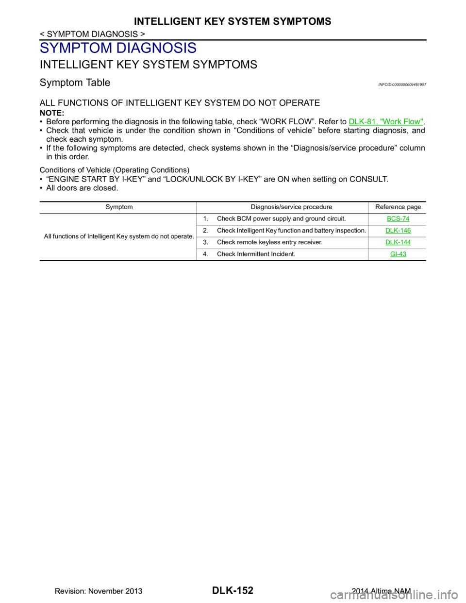
Symptom TableINFOID:0000000009461907
ALL FUNCTIONS OF INTELLIGENT KEY SYSTEM DO NOT OPERATE
NOTE:
• Before performing the diagnosis in the following table, check “WORK FLOW”. Refer to DLK-81, "Work Flow"
.
• Check that vehicle is under the condition shown in “Conditions of vehicle” before starting diagnosis, and
check each symptom.
• If the following symptoms are detected, check syst ems shown in the “Diagnosis/service procedure” column
in this order.
Conditions of Vehicle (Operating Conditions)
• “ENGINE START BY I-KEY” and “LOCK/UNLOCK BY I-KEY” are ON when setting on CONSULT.
• All doors are closed.
Symptom Diagnosis/service procedure Reference page
All functions of Intelligent Key system do not operate. 1. Check BCM power supply and ground circuit.
BCS-74
2. Check Intelligent Key function and battery inspection.DLK-146
3. Check remote keyless entry receiver.DLK-144
4. Check Intermittent Incident. GI-43
Revision: November 20132014 Altima NAMRevision: November 20132014 Altima NAM
Page 922 of 4801

DLK-154
< SYMPTOM DIAGNOSIS >
DOOR LOCK FUNCTION SYMPTOMS
Conditions of Vehicle (Operating Conditions)
• “LOCK/UNLOCK BY I-KEY” is ON when setting on CONSULT.
• Intelligent Key is out of key slot.
• All doors are closed.
INTELLIGENT KEY
INTELLIGENT KEY : Symptom TableINFOID:0000000009461910
REMOTE KEYLESS ENTRY FUNCTION MALFUNCTION
NOTE:
• Before performing the diagnosis in the following table, check “WORK FLOW”. Refer to DLK-81, "Work Flow"
.
• Check that vehicle is under the condition shown in “Conditions of vehicle” before starting diagnosis, and
check each symptom.
• If the following symptoms are detected, check syst ems shown in the “Diagnosis/service procedure” column
in this order.
Conditions of Vehicle (Operating Conditions)
• Intelligent Key is out of key slot.
• Ignition switch is in OFF or ACC position.
• All doors are closed.
• Retained power operation does not operate.
Symptom Diagnosis/service procedure Reference
page
Door lock/unlock system does not operate by
door request switch. 1. Check BCM power supply and ground circuit.
BCS-74
2. Check door switch.DLK-100
3. Check Intermittent Incident. GI-43
Door lock/unlock system does not operate by
request switch (driver side). 1. Check door request
switch (driver side). DLK-1292. Check outside key antenna (driver side). D L K - 111
3. Check Intermittent Incident. GI-43
Door lock/unlock system does not operate by
request switch (passenger side). 1. Check door request switch (passenger side).
DLK-1292. Check outside key antenna (passenger side).DLK-109
3. Check Intermittent Incident. GI-43
Selective unlock function does not operate by
door request switch (dri ver side) (other door
lock function operate). 1.
Check “DOOR LOCK-UNLOCK
SET” setting in “WORK
SUPPORT”. DLK-43
2.
Check selective unlock function with a remote controller
or door key cylinder. DLK-103
3. Check Intermittent Incident.
GI-43
Selective unlock function does not operate by
door request switch (passenger side) (other
door lock functions operate). 1.
Check “DOOR LOCK-UNLOCK
SET” setting in “WORK
SUPPORT”. DLK-43
2. Check Intermittent Incident.
GI-43
Auto lock function does not operate.1.
Check “AUTO LOCK SET” setting in “WORK SUP-
PORT”. DLK-432. Check door switch.
DLK-100
3. Check Intermittent Incident. GI-43
Symptom Diagnosis/service procedure Reference
page
All of the remote keyless entry functions do
not operate. 1. Check Intelligent Key battery inspection.
DLK-146
2. Check Intermittent Incident. GI-43
Revision: November 20132014 Altima NAMRevision: November 20132014 Altima NAM
Page 923 of 4801

DOOR LOCK FUNCTION SYMPTOMSDLK-155
< SYMPTOM DIAGNOSIS >
C
D E
F
G H
I
J
L
M A
B
DLK
N
O P
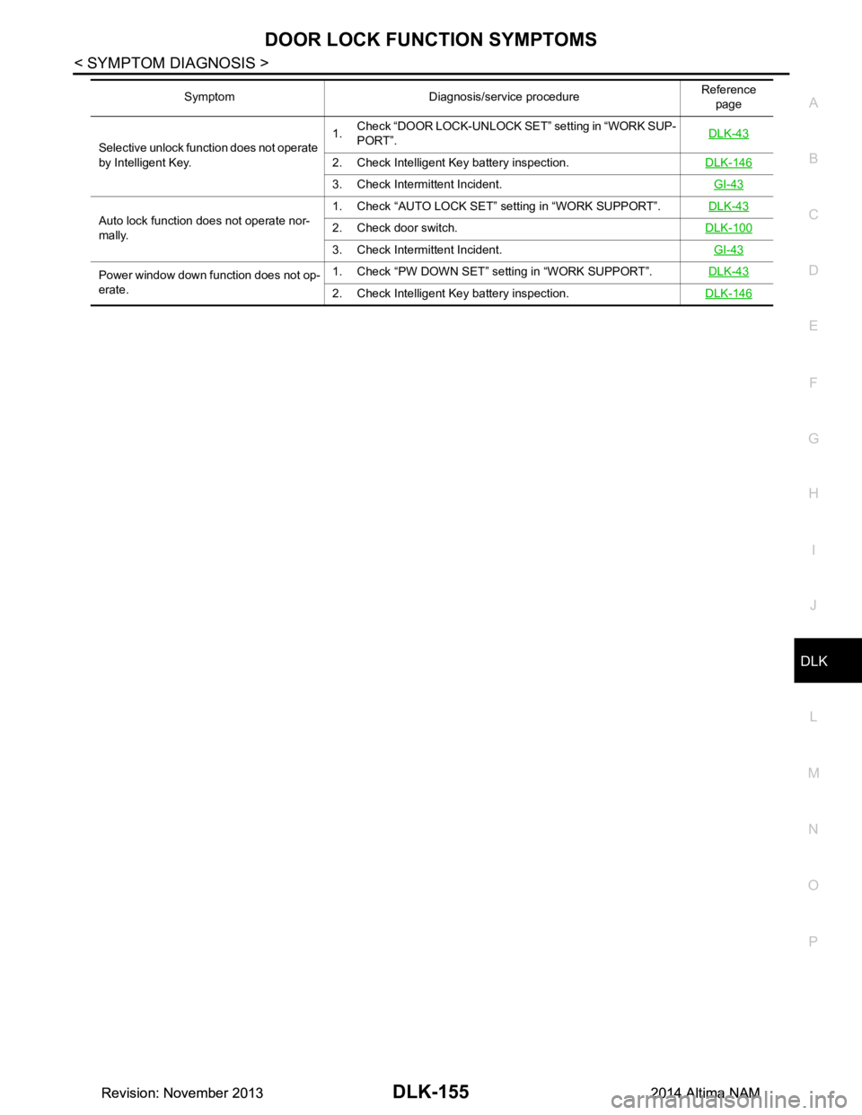
Selective unlock function does not operate
by Intelligent Key. 1.
Check “DOOR LOCK-UNLOCK SET” setting in “WORK SUP-
PORT”. DLK-43
2. Check Intelligent Key battery inspection.
DLK-146
3. Check Intermittent Incident. GI-43
Auto lock function does not operate nor-
mally. 1. Check “AUTO LOCK SET” setting in “WORK SUPPORT”.
DLK-432. Check door switch.DLK-100
3. Check Intermittent Incident. GI-43
Power window down function does not op-
erate. 1. Check “PW DOWN SET” se
tting in “WORK SUPPORT”. DLK-43
2. Check Intelligent Key battery inspection. DLK-146
Symptom Diagnosis/service procedure Reference
page
Revision: November 20132014 Altima NAMRevision: November 20132014 Altima NAM
Page 925 of 4801

TRUNK OPEN FUNCTION SYMPTOMSDLK-157
< SYMPTOM DIAGNOSIS >
C
D E
F
G H
I
J
L
M A
B
DLK
N
O P
Symptom Diagnosis/service procedure Reference page
Trunk open function does not operate by Intel-
ligent Key. 1.
Check “TRUNK OPEN DELA
Y” setting in “WORK
SUPPORT”. DLK-43
2. Check trunk open function.
DLK-122
3. Check trunk lamp switch.DLK-126
4. Check Intelligent Key battery inspection.DLK-146
5. Check Intermittent Incident. GI-43
Revision: November 20132014 Altima NAMRevision: November 20132014 Altima NAM