Page 2521 of 4801

FSU-20
< UNIT REMOVAL AND INSTALLATION >
FRONT SUSPENSION ASSEMBLY
Removal and Installation
INFOID:0000000009460637
QR25DE ENGINE
Removal
1. Remove front wheel and tire using power tool. Refer to WT-55, "Adjustment".
2. Remove each brake caliper using power tool, leaving brake caliper hydraulic hose attached. Position each brake caliper aside with wire. Refer to BR-36, "BRAKE CALIPER ASSEMBLY : Exploded View"
.
CAUTION:
• Do not depress brake pedal while brake caliper is removed.
• Do not twist or stretch the brake hose.
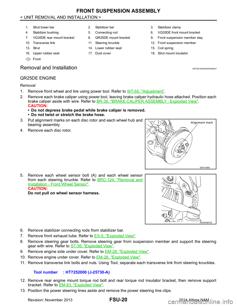
3. Put alignment marks on each disc rotor and each wheel hub and bearing assembly.
4. Remove each disc rotor.
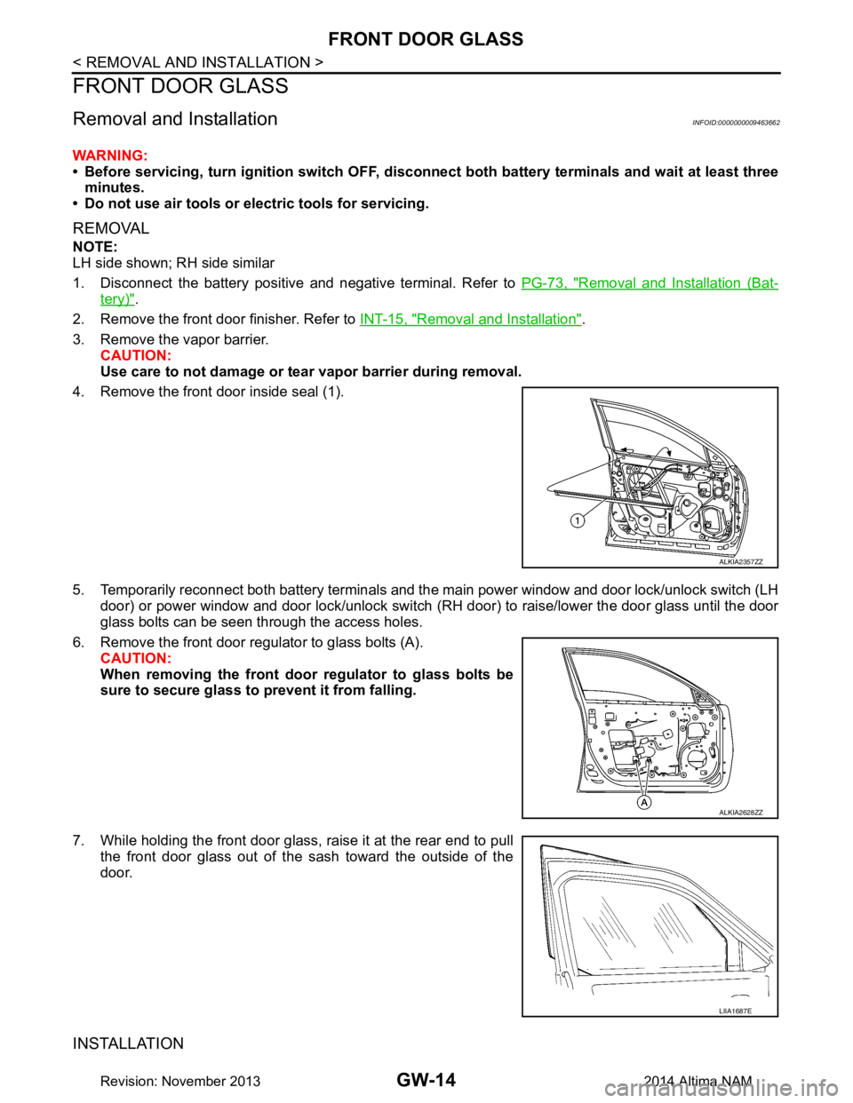
5. Remove each wheel sensor bolt (A) and each wheel sensor from each steering knuckle. Refer to BRC-124, "Removal and
Installation - Front Wheel Sensor".
CAUTION:
Do not pull on wheel sensor harness.
6. Remove stabilizer connecting rods from stabilizer bar.
7. Remove front exhaust tube. Refer to EX-5, "Exploded View"
.
8. Remove steering gear bolts. Remove steering gear from suspension member and support the steering gear with wire. Refer to ST-36, "Exploded View"
.
9. Remove engine side under cover. Refer to EM-28, "Exploded View"
.
10. Remove engine under cover. Refer to EM-28, "Exploded View"
.
11. Remove transverse link bolts and nuts. Using Tool, separate each transverse link from steering knuckles.
12. Remove rear engine mount torque rod bolt and rear torque rod insulator bracket, then remove support bracket. Refer to EM-83, "Exploded View"
.
13. Position the power steering lines aside and remove the power steering line clips.
1. Strut tower bar 2. Stabilizer bar 3. Stabilizer clamp
4. Stabilizer bushing 5. Connecting rod 6. VQ35DE front mount bracket
7. VQ35DE rear mount bracket 8. QR25DE mount bracket 9. Front suspension member stay
10. Transverse link 11. Steering knuckle 12. Front suspension member
13. Strut 14. Lower rubber seat 15. Coil spring
16. Upper rubber seat 17. Dust cover 18. Strut mount insulator
Front
SDIA1480E
ALDIA0287ZZ
Tool number : HT7252000 (J-25730-A)
Revision: November 20132014 Altima NAM
Page 2594 of 4801

GW-14
< REMOVAL AND INSTALLATION >
FRONT DOOR GLASS
FRONT DOOR GLASS
Removal and InstallationINFOID:0000000009463662
WARNING:
• Before servicing, turn ignition sw itch OFF, disconnect both battery terminals and wait at least three
minutes.
• Do not use air tools or el ectric tools for servicing.
REMOVAL
NOTE:
LH side shown; RH side similar
1. Disconnect the battery positive and negative terminal. Refer to PG-73, "Removal and Installation (Bat-
tery)".
2. Remove the front door finisher. Refer to INT-15, "Removal and Installation"
.
3. Remove the vapor barrier. CAUTION:
Use care to not damage or tear vapor barrier during removal.
4. Remove the front door inside seal (1).
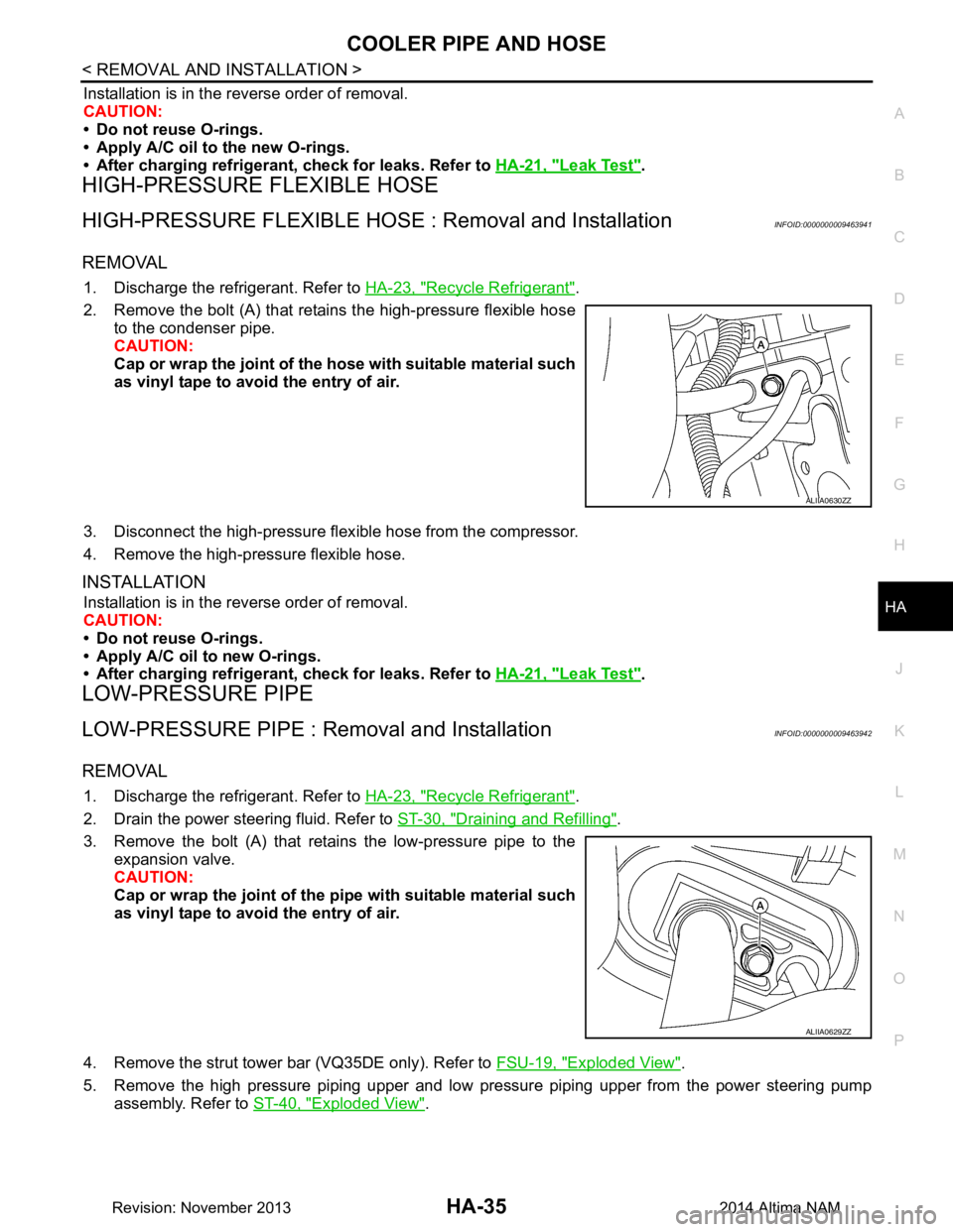
5. Temporarily reconnect both battery terminals and the main power window and door lock/unlock switch (LH door) or power window and door lock/unlock switch ( RH door) to raise/lower the door glass until the door
glass bolts can be seen through the access holes.
6. Remove the front door regul ator to glass bolts (A).
CAUTION:
When removing the front door regulator to glass bolts be
sure to secure glass to prevent it from falling.
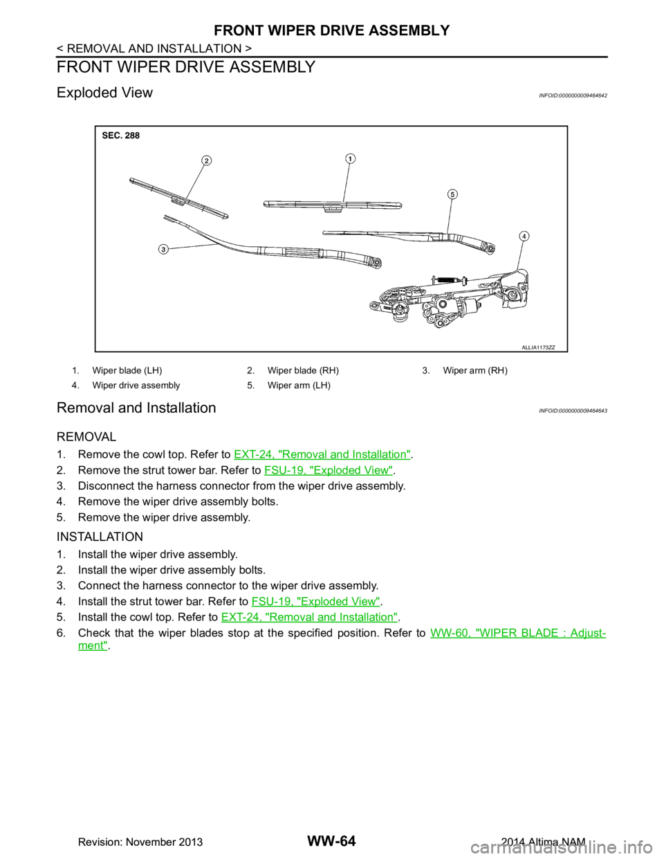
7. While holding the front door glass, raise it at the rear end to pull the front door glass out of the sash toward the outside of the
door.
INSTALLATION
ALKIA2357ZZ
ALKIA2628ZZ
LIIA1687E
Revision: November 20132014 Altima NAM
Page 2641 of 4801

COOLER PIPE AND HOSEHA-35
< REMOVAL AND INSTALLATION >
C
D E
F
G H
J
K L
M A
B
HA
N
O P
Installation is in the reverse order of removal.
CAUTION:
• Do not reuse O-rings.
• Apply A/C oil to the new O-rings.
• After charging refrigerant, check for leaks. Refer to HA-21, "Leak Test"
.
HIGH-PRESSURE FLEXIBLE HOSE
HIGH-PRESSURE FLEXIBLE HOSE : Removal and InstallationINFOID:0000000009463941
REMOVAL
1. Discharge the refrigerant. Refer to HA-23, "Recycle Refrigerant".
2. Remove the bolt (A) that retains the high-pressure flexible hose to the condenser pipe.
CAUTION:
Cap or wrap the joint of the ho se with suitable material such
as vinyl tape to avoid the entry of air.
3. Disconnect the high-pressure flex ible hose from the compressor.
4. Remove the high-pressure flexible hose.
INSTALLATION
Installation is in the reverse order of removal.
CAUTION:
• Do not reuse O-rings.
• Apply A/C oil to new O-rings.
• After charging refrigerant, check for leaks. Refer to HA-21, "Leak Test"
.
LOW-PRESSURE PIPE
LOW-PRESSURE PIPE : Re moval and InstallationINFOID:0000000009463942
REMOVAL
1. Discharge the refrigerant. Refer to HA-23, "Recycle Refrigerant".
2. Drain the power steering fluid. Refer to ST-30, "Draining and Refilling"
.
3. Remove the bolt (A) that retains the low-pressure pipe to the expansion valve.
CAUTION:
Cap or wrap the joint of the pi pe with suitable material such
as vinyl tape to avoid the entry of air.
4. Remove the strut tower bar (VQ35DE only). Refer to FSU-19, "Exploded View"
.
5. Remove the high pressure piping upper and low pressure piping upper from the power steering pump assembly. Refer to ST-40, "Exploded View"
.
ALIIA0630ZZ
ALIIA0629ZZ
Revision: November 20132014 Altima NAM
Page 2642 of 4801
HA-36
< REMOVAL AND INSTALLATION >
COOLER PIPE AND HOSE
6. Remove the bolt (A) that retains the low-pressure pipe to thelow-pressure flexible hose.
7. Remove the low-pressure pipe.
INSTALLATION
Installation is in the reverse order of removal.
CAUTION:
• Do not reuse O-rings.
• Apply A/C oil to new O-rings.
• After charging refrigerant, check for leaks. Refer to HA-21, "Leak Test"
.
HIGH-PRESSURE PIPE
HIGH-PRESSURE PIPE : Removal and InstallationINFOID:0000000009463943
REMOVAL
1. Discharge the refrigerant. Refer to HA-23, "Recycle Refrigerant".
2. Remove the power steering pump assembly. Refer to ST-38, "Removal and Installation"
.
3. Remove the strut tower bar. Refer to FSU-19, "Exploded View"
.
4. Remove the coolant overflow reservoir tube (A).
5. Remove the coolant overflow reservoir bolt (B).
6. Remove the coolant overflow reservoir (1).
ALIIA0627ZZ
ALIIA0621ZZ
Revision: November 20132014 Altima NAM
Page 4799 of 4801

WW-64
< REMOVAL AND INSTALLATION >
FRONT WIPER DRIVE ASSEMBLY
FRONT WIPER DRIVE ASSEMBLY
Exploded ViewINFOID:0000000009464642
Removal and InstallationINFOID:0000000009464643
REMOVAL
1. Remove the cowl top. Refer to EXT-24, "Removal and Installation".
2. Remove the strut tower bar. Refer to FSU-19, "Exploded View"
.
3. Disconnect the harness connector from the wiper drive assembly.
4. Remove the wiper drive assembly bolts.
5. Remove the wiper drive assembly.
INSTALLATION
1. Install the wiper drive assembly.
2. Install the wiper drive assembly bolts.
3. Connect the harness connector to the wiper drive assembly.
4. Install the strut tower bar. Refer to FSU-19, "Exploded View"
.
5. Install the cowl top. Refer to EXT-24, "Removal and Installation"
.
6. Check that the wiper blades stop at the specified position. Refer to WW-60, "WIPER BLADE : Adjust-
ment".
1. Wiper blade (LH) 2. Wiper blade (RH) 3. Wiper arm (RH)
4. Wiper drive assembly 5. Wiper arm (LH)
ALLIA1173ZZ
Revision: November 20132014 Altima NAMRevision: November 20132014 Altima NAM