2014 NISSAN TEANA fuel cap release
[x] Cancel search: fuel cap releasePage 2162 of 4801
![NISSAN TEANA 2014 Service Manual
EM-164
< REMOVAL AND INSTALLATION >[VQ35DE]
FUEL INJECTOR AND FUEL TUBE
6. Remove the electric throttle cont
rol actuator bolts in the reverse
order as shown and remove the electric throttle control NISSAN TEANA 2014 Service Manual
EM-164
< REMOVAL AND INSTALLATION >[VQ35DE]
FUEL INJECTOR AND FUEL TUBE
6. Remove the electric throttle cont
rol actuator bolts in the reverse
order as shown and remove the electric throttle control](/manual-img/5/57390/w960_57390-2161.png)
EM-164
< REMOVAL AND INSTALLATION >[VQ35DE]
FUEL INJECTOR AND FUEL TUBE
6. Remove the electric throttle cont
rol actuator bolts in the reverse
order as shown and remove the electric throttle control actuator
and position aside.
CAUTION:
• Handle carefully to avoid any shock to the electric throttle
control actuator.
• Do not disassemble.
7. Remove intake manifold collector. Refer to EM-146, "Removal and Installation"
.
8. When separating fuel feed hose and fuel tube connection, disconnect quick connector as follows:
a. Remove quick connector cap from quick connector.
b. Disconnect quick connector from fuel tube as follows: CAUTION:
Disconnect quick connector by using the quick connector release (commercial service tool: J-
45488), not by picking out retainer tabs.
i. With the sleeve side of quick connector release fa cing to quick connector, install the quick connector
release onto fuel tube.
ii. Insert the quick connector release (A) into quick connector (2) until sleeve (B) contacts and goes no further. Hold quick connec-
tor release on that position.
CAUTION:
Inserting quick connector re lease hard will not disconnect
quick connector. Hold qui ck connector release where it
contacts and goes no further.
iii. Draw and pull out quick connector straight from fuel tube (1). CAUTION:
• Do not reuse O-ring.
• Pull quick connector (E) ho lding position (D) as shown.
• Do not pull with lateral force applied. O-ring inside quick connector may be damaged.
• Prepare container and cloth beforehand as fuel will leak out.
• Avoid fire and sparks.
• Keep parts away from heat source. Especially, be careful when welding is performed around
them.
• Do not expose parts to battery electrolyte or other acids.
• Do not bend or twist connection between quick connector and fuel feed hose (with damper) dur-
ing installati on/removal.
• To keep clean the connecting portion and to avoid dam-
age and foreign materials, cover them completely with
plastic bags, etc. (A) or something similar.
9. Disconnect harness connector from fuel injector.
SEM711G
(C) : Insert and retain
JPBIA0033ZZ
JPBIA0035ZZ
Revision: November 20132014 Altima NAM
Page 2219 of 4801
![NISSAN TEANA 2014 Service Manual
ENGINE ASSEMBLYEM-221
< UNIT REMOVAL AND INSTALLATION > [VQ35DE]
C
D E
F
G H
I
J
K L
M A
EM
NP
O
• Do not damage the edge of the crankshaft
position sensor (POS) or the ring gear teeth.
REMOVAL
NISSAN TEANA 2014 Service Manual
ENGINE ASSEMBLYEM-221
< UNIT REMOVAL AND INSTALLATION > [VQ35DE]
C
D E
F
G H
I
J
K L
M A
EM
NP
O
• Do not damage the edge of the crankshaft
position sensor (POS) or the ring gear teeth.
REMOVAL](/manual-img/5/57390/w960_57390-2218.png)
ENGINE ASSEMBLYEM-221
< UNIT REMOVAL AND INSTALLATION > [VQ35DE]
C
D E
F
G H
I
J
K L
M A
EM
NP
O
• Do not damage the edge of the crankshaft
position sensor (POS) or the ring gear teeth.
REMOVAL
NOTE:
When removing components such as hoses, tubes/lines, etc. , cap or plug openings to prevent fluid from spill-
ing.
1. Remove hood assembly. Refer to DLK-170, "HOOD ASSEMBLY : Removal and Installation"
.
2. Release fuel pressure. Refer to FL-5, "Inspection"
.
3. Drain engine coolant. Refer to CO-36, "Changing Engine Coolant"
.
4. Drain power steering fluid. Refer to ST-30, "Draining and Refilling"
.
5. Remove front wheels and tires (RH/LH). Refer to WT-55, "Adjustment"
.
6. Remove fender protector side covers (RH/LH). Refer to EXT-26, "FENDER PROTECTOR : Removal and
Installation".
7. Remove the engine under cover. Refer to EXT-17, "Removal and Installation"
.
8. Remove the engine room cover. Refer to EM-143, "Removal and Installation"
.
9. Remove air duct hose and resonator assembly and air cleaner case assembly with mass air flow sensor.
Refer to EM-144, "Removal and Installation"
.
10. Remove battery and battery tray. Refer to PG-74, "Removal and Installation (Battery Tray)"
.
11. Remove transmission control module. Refer to TM-183, "Removal and Installation"
.
12. Remove cowl top. Refer to EXT-24, "Removal and Installation"
.
13. Remove strut brace using power tools. Refer to FSU-19, "Exploded View"
.
14. Remove IPDM E/R. Refer to PCS-32, "Removal and Installation"
.
15. Remove the following parts: • EVAP vacuum hose
• Brake booster vacuum hose
• Heater hoses (engine side)
16. Disconnect transaxle shift control cables. Refer to TM-380, "Removal and Installation"
.
17. Remove upper and lower radiator hoses.
18. Disconnect CVT fluid cooler hoses.
19. Remove power steering reservoir, suction hose and high pressure hose.
20. Disconnect fuel hose quick connection at vehicle piping side. Refer to EM-163, "Removal and Installa-
tion".
21. Remove the front exhaust tube using power tools. Refer to EX-10, "Exploded View"
.
22. Discharge and recover the R134a refrigerant. Refer to HA-23, "Recycle Refrigerant"
.
23. Remove the A/C compressor using power tools. Refer to HA-30, "COMPRESSOR : Removal and Installa-
tion".
24. Install engine slingers into front of LH cylinder head and rear of RH cylinder head.
• (A): RH cylinder head
ALBIA0262GB
Revision: November 20132014 Altima NAM
Page 2486 of 4801
FL-6
< REMOVAL AND INSTALLATION >
FUEL LEVEL SENSOR UNIT, FUEL FILTER AND FUEL PUMP ASSEMBLY
REMOVAL AND INSTALLATION
FUEL LEVEL SENSOR UNIT, FUEL FILTER AND FUEL PUMP ASSEMBLY
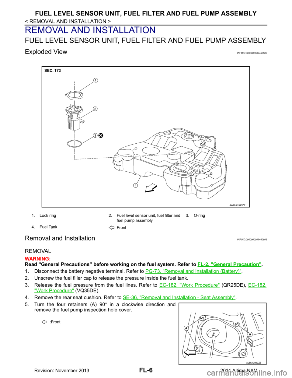
Exploded ViewINFOID:0000000009460602
Removal and InstallationINFOID:0000000009460603
REMOVAL
WARNING:
Read “General Precautions” before wo rking on the fuel system. Refer to FL-2, "General Precaution"
.
1. Disconnect the battery negative terminal. Refer to PG-73, "Removal and Installation (Battery)"
.
2. Unscrew the fuel filler cap to release the pressure inside the fuel tank.
3. Release the fuel pressure from the fuel lines. Refer to EC-182, "Work Procedure"
(QR25DE), EC-182,
"Work Procedure" (VQ35DE).
4. Remove the rear seat cushion. Refer to SE-36, "Removal and Installation - Seat Assembly"
.
5. Turn the four retainers (A) 90 ° in a clockwise direction and
remove the fuel pump inspection hole cover.
1. Lock ring 2. Fuel level sensor unit, fuel filter and
fuel pump assembly3. O-ring
4. Fuel Tank Front
AWBIA1345ZZ
:Front
ALBIA0892ZZ
Revision: November 20132014 Altima NAM
Page 2491 of 4801
FUEL TANKFL-11
< REMOVAL AND INSTALLATION >
C
D E
F
G H
I
J
K L
M A
FL
NP
O
• As a guide, if the fuel tank is full the fuel leve
l reaches or is less than the level on the fuel gauge as
shown, when approximately 34 (9 US gal, 7 1/2 Imp gal) of fuel is drained from a full fuel tank.
3. Open the fuel filler cap to release the pressure inside the fuel tank.
4. Release fuel pressure from fuel line. Refer to EC-182, "Work Procedure"
(QR25DE), EC-687, "Work Pro-
cedure" (VQ35DE).
5. Remove rear seat cushion. Refer to SE-36, "Removal and Installation - Seat Assembly"
.
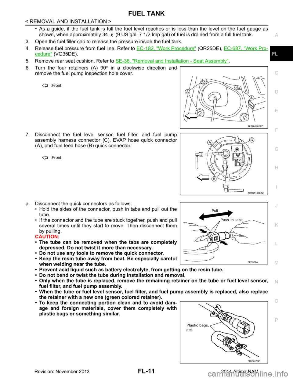
6. Turn the four retainers (A) 90 ° in a clockwise direction and
remove the fuel pump inspection hole cover.
7. Disconnect the fuel level sensor, fuel filter, and fuel pump assembly harness connector (C), EVAP hose quick connector
(A), and fuel feed hose (B) quick connector.
a. Disconnect the quick connectors as follows: • Hold the sides of the connector, push in tabs and pull out the
tube.
• If the connector and the tube are stuck together, push and pull
several times until they start to move. Then disconnect them
by pulling.
CAUTION:
• The tube can be removed when the tabs are completely depressed. Do not twist it more than necessary.
• Do not use any tools to remove the quick connector.
• Keep the resin tube away from heat. Be especially careful
when welding near the tube.
• Prevent acid liquid such as battery elect rolyte, from getting on the resin tube.
• Do not bend or twist the tube during installation and removal.
• Only when the tube is replaced, remove the remaining retainer on the tube or fuel level sensor,
fuel filter, and fuel pump assembly.
• When the tube or fuel level sen sor, fuel filter, and fuel pump assembly is replaced, also replace
the retainer with a new one (green colored retainer).
• To keep the connecting portio n clean and to avoid dam-
age and foreign materials, cover them completely with
plastic bags or something similar.
:Front
ALBIA0892ZZ
:Front
AWBIA1308ZZ
SFE562A
PBIC0163E
Revision: November 20132014 Altima NAM
Page 3268 of 4801
MWI
SYSTEMMWI-13
< SYSTEM DESCRIPTION >
C
D E
F
G H
I
J
K L
M B
A
O P
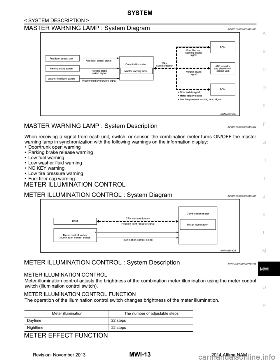
MASTER WARNING LAMP : System DiagramINFOID:0000000009461683
MASTER WARNING LAMP : System DescriptionINFOID:0000000009461684
When receiving a signal from each unit, switch, or s ensor, the combination meter turns ON/OFF the master
warning lamp in synchronization with the following warnings on the information display:
• Door/trunk open warning
• Parking brake release warning
• Low fuel warning
• Low washer fluid warning
• NO KEY warning
• Low tire pressure warning
• Fuel filler cap warning
METER ILLUMINATION CONTROL
METER ILLUMINATION CONTROL : System DiagramINFOID:0000000009461685
METER ILLUMINATION CONTROL : System DescriptionINFOID:0000000009461686
METER ILLUMINATION CONTROL
Meter illumination control adjusts the brightness of the combination meter illumination using the meter control
switch (illumination control switch).
METER ILLUMINATION CONTROL FUNCTION
The operation of the illumination control switch changes brightness of the meter illumination.
METER EFFECT FUNCTION
AWNIA2975GB
AWNIA2548GB
Meter illumination The number of adjustable steps
Daytime 22 steps
Nighttime 22 steps
Revision: November 20132014 Altima NAMRevision: November 20132014 Altima NAM
Page 3270 of 4801
MWI
SYSTEMMWI-15
< SYSTEM DESCRIPTION >
C
D E
F
G H
I
J
K L
M B
A
O P
Engine-start effect exits when any of the above operat ional conditions is cancelled during the engine-start
effect.
INFORMATION DISPLAY
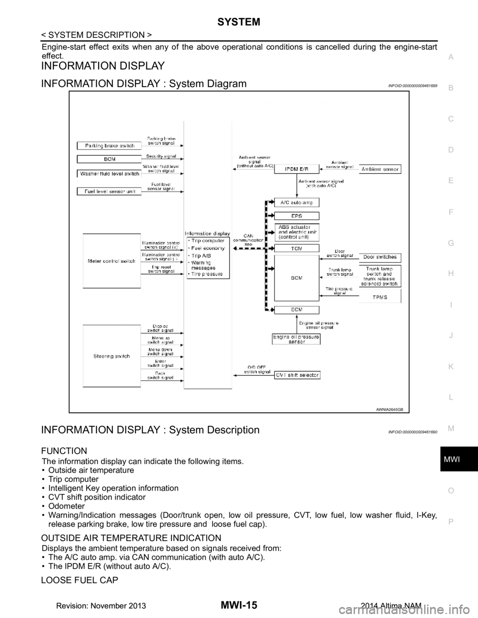
INFORMATION DISPLAY : System DiagramINFOID:0000000009461689
INFORMATION DISPLAY : System DescriptionINFOID:0000000009461690
FUNCTION
The information display can indicate the following items.
• Outside air temperature
• Trip computer
• Intelligent Key operation information
• CVT shift position indicator
• Odometer
• Warning/Indication messages (Door/trunk open, low oil pressure, CVT, low fuel, low washer fluid, I-Key,
release parking brake, low tire pressure and loose fuel cap).
OUTSIDE AIR TEMPERATURE INDICATION
Displays the ambient temperature based on signals received from:
• The A/C auto amp. via CAN communication (with auto A/C).
• The IPDM E/R (without auto A/C).
LOOSE FUEL CAP
AWNIA2645GB
Revision: November 20132014 Altima NAMRevision: November 20132014 Altima NAM
Page 3271 of 4801
MWI-16
< SYSTEM DESCRIPTION >
SYSTEM
The LOOSE FUEL CAP message will display in the information display when the fuel-filler cap is not tightened
correctly. The message will turn off as soon as the EC M detects the fuel-filler cap is properly tightened. The
ECM provides a loose fuel cap signal to the combination meter via CAN communication.
LOW TIRE PRESSURE WARNING
This warning appears when the BCM detects low inflati on pressure or a system malfunction. The BCM sends
a signal to the combination meter via CAN communication to illuminate the low tire pressure warning lamp. In
addition, a warning message will be displayed in the vehicle information display.
DOOR OPEN WARNING
This warning appears when the ignition switch is ON and the door is open. The BCM receives a door switch
signal from the door open door switch. The BCM sends t he door switch signal to the combination meter via
CAN communication lines.
TRUNK OPEN WARNING
This warning appears when the ignition switch is ON and the trunk is opened. The BCM receives a trunk lamp
switch signal from the trunk lamp switch. The BCM s ends the trunk lamp switch signal to the combination
meter via CAN communication.
LOW FUEL WARNING
This warning appears when the fuel level in the fuel tank is less than approximately 4 US gal (15 L, 3.3 Imp
gal). A variable resistor signal is supplied to the combi nation meter from the fuel level sensor unit to determine
the amount of fuel in the fuel tank.
LOW WINDSHIELD WASHER FLUID WARNING
When the windshield washer fluid level is low, the was her fluid level switch provides a ground signal to the
combination meter and the warning is displayed. Once fluid is added, the switch opens and the warning is no
longer displayed.
RELEASE PARKING BRAKE WARNING
When the parking brake is applied, the parking brake switch provides a ground signal to the combination
meter. When the vehicle speed is greater than 4 MPH (7 km/h), the message is displayed and the warning
chime sounds.
SHIFT POSITION INDICATOR
Displays the position of the shift selector based on signals received from TCM via CAN communication.
LOW OIL PRESSURE WARNING
The low oil pressure warning appears in the information display when the combination meter receives a low
engine oil pressure signal from the ECM via CAN communication.
WARNING CHECK INDICATION
The combination meter can cause an interrupt on the information display to indicate a warning, based on sig-
nals received from each unit and switch.
Refer to Owner’s Manual for additional information display items.
COMPASS
COMPASS : DescriptionINFOID:0000000009461691
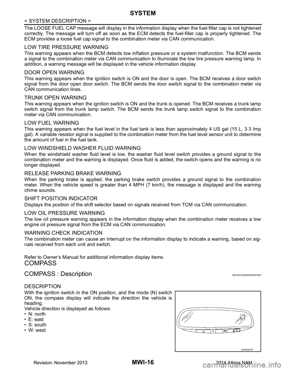
DESCRIPTION
With the ignition switch in the ON position, and the mode (N) switch
ON, the compass display will indicate the direction the vehicle is
heading.
Vehicle direction is displayed as follows:
• N: north
• E: east
• S: south
•W: west
LKIA0447E
Revision: November 20132014 Altima NAMRevision: November 20132014 Altima NAM