2014 NISSAN TEANA clutch
[x] Cancel search: clutchPage 2626 of 4801

HA-20
< SYMPTOM DIAGNOSIS >
NOISE
NOISE
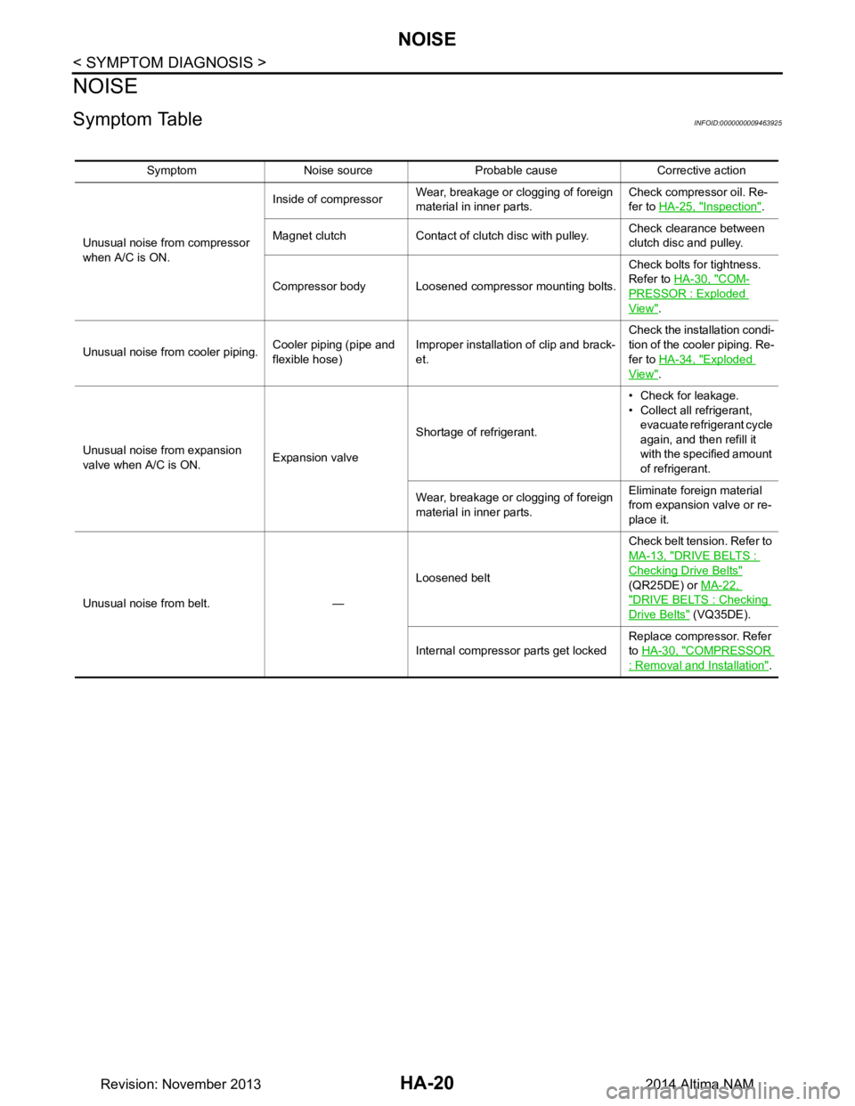
Symptom TableINFOID:0000000009463925
Symptom Noise source Probable cause Corrective action
Unusual noise from compressor
when A/C is ON. Inside of compressor
Wear, breakage or clogging of foreign
material in inner parts. Check compressor oil. Re-
fer to HA-25, "Inspection"
.
Magnet clutch Contact of clutch disc with pulley. Check clearance between
clutch disc and pulley.
Compressor body Loosened compressor mounting bolts. Check bolts for tightness.
Refer to HA-30, "COM-
PRESSOR : Exploded
View".
Unusual noise from cooler piping. Cooler piping (pipe and
flexible hose) Improper installation of clip and brack-
et. Check the installation condi-
tion of the cooler piping. Re-
fer to HA-34, "Exploded
View".
Unusual noise from expansion
valve when A/C is ON. Expansion valveShortage of refrigerant. • Check for leakage.
• Collect all refrigerant,
evacuate refrigerant cycle
again, and then refill it
with the specified amount
of refrigerant.
Wear, breakage or clogging of foreign
material in inner parts. Eliminate foreign material
from expansion valve or re-
place it.
Unusual noise from belt. — Loosened beltCheck belt tension. Refer to
MA-13, "DRIVE BELTS :
Checking Drive Belts"
(QR25DE) or MA-22,
"DRIVE BELTS : Checking
Drive Belts" (VQ35DE).
Internal compressor parts get locked Replace compressor. Refer
to HA-30, "COMPRESSOR
: Removal and Installation".
Revision: November 20132014 Altima NAM
Page 2637 of 4801

COMPRESSORHA-31
< REMOVAL AND INSTALLATION >
C
D E
F
G H
J
K L
M A
B
HA
N
O P
4. Remove the drive belt. Refer to EM-19, "Removal and Installation" (QR25DE), or EM-134, "Removal and
Installation" (VQ35DE).
5. Reposition the power steering line. Refer to ST-40, "Exploded View"
.
6. Disconnect the A/C pipes from the compressor. CAUTION:
Cap or wrap the joint of the A/C pipes with suitable material such as vinyl tape to avoid the entry of
air.
7. Disconnect the harness connector from the compressor.
8. Remove the compressor bolts and the compressor.
INSTALLATION
Installation is in the reverse order of removal.
CAUTION:
• Do not reuse the O-rings.
• Apply A/C compressor oil to th e new O-rings for installation.
• After charging the A/C refriger ant, check for leaks. Refer to HA-21, "Leak Test"
.
• Tighten the compressor bolts to specification. Refer to HA-30, "COMPRESSOR : Exploded View"
.
MAGNET CLUTCH
MAGNET CLUTCH : Removal and InstallationINFOID:0000000009463938
REMOVAL
1. Remove the front under cover. Refer to EXT-28, "Removal and Installation".
2. Partially remove the fender protector (RH). Refer to EXT-26, "FENDER PROTECTOR : Removal and
Installation".
3. Remove the drive belt. Refer to EM-19, "Removal and Installation"
(QR25DE), or EM-134, "Removal and
Installation" (VQ35DE).
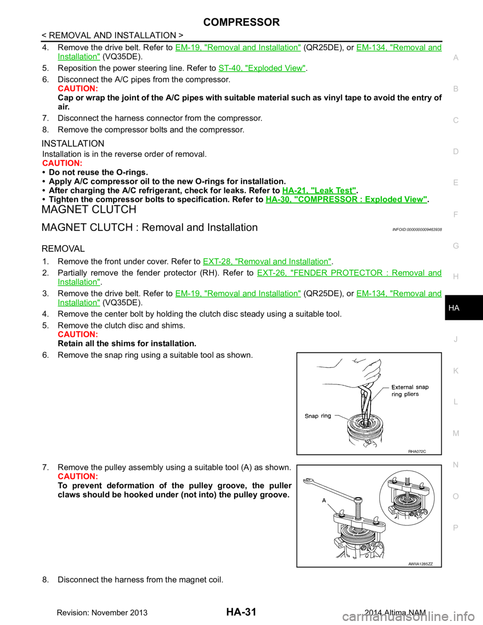
4. Remove the center bolt by holding the clutch disc steady using a suitable tool.
5. Remove the clutch disc and shims. CAUTION:
Retain all the shim s for installation.
6. Remove the snap ring using a suitable tool as shown.
7. Remove the pulley assembly using a suitable tool (A) as shown. CAUTION:
To prevent deformation of th e pulley groove, the puller
claws should be hooked under (not into) the pulley groove.
8. Disconnect the harness from the magnet coil.
RHA072C
AWIIA1285ZZ
Revision: November 20132014 Altima NAM
Page 2638 of 4801

HA-32
< REMOVAL AND INSTALLATION >
COMPRESSOR
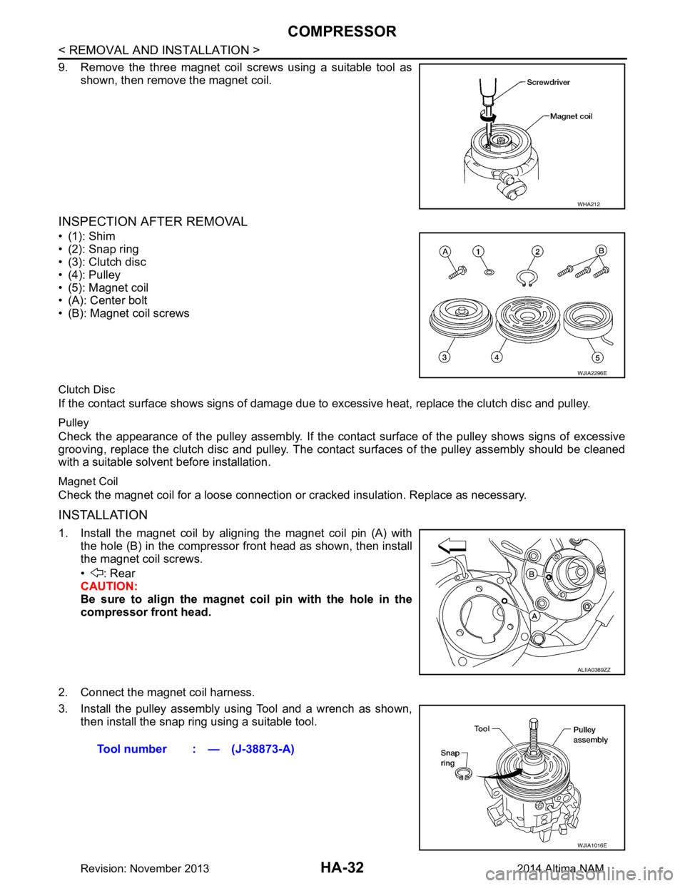
9. Remove the three magnet coil screws using a suitable tool asshown, then remove the magnet coil.
INSPECTION AFTER REMOVAL
•(1): Shim
• (2): Snap ring
• (3): Clutch disc
• (4): Pulley
• (5): Magnet coil
• (A): Center bolt
• (B): Magnet coil screws
Clutch Disc
If the contact surface shows signs of damage due to excessive heat, replace the clutch disc and pulley.
Pulley
Check the appearance of the pulley assembly. If the cont act surface of the pulley shows signs of excessive
grooving, replace the clutch disc and pulley. The contact surfaces of the pulley assembly should be cleaned
with a suitable solvent before installation.
Magnet Coil
Check the magnet coil for a loose connection or cracked insulation. Replace as necessary.
INSTALLATION
1. Install the magnet coil by aligning the magnet coil pin (A) with
the hole (B) in the compressor front head as shown, then install
the magnet coil screws.
• : Rear
CAUTION:
Be sure to align the magnet coil pin with the hole in the
compressor front head.
2. Connect the magnet coil harness.
3. Install the pulley assembly using Tool and a wrench as shown, then install the snap ring using a suitable tool.
WHA212
WJIA2296E
ALIIA0389ZZ
Tool number : — (J-38873-A)
WJIA1016E
Revision: November 20132014 Altima NAM
Page 2639 of 4801

COMPRESSORHA-33
< REMOVAL AND INSTALLATION >
C
D E
F
G H
J
K L
M A
B
HA
N
O P
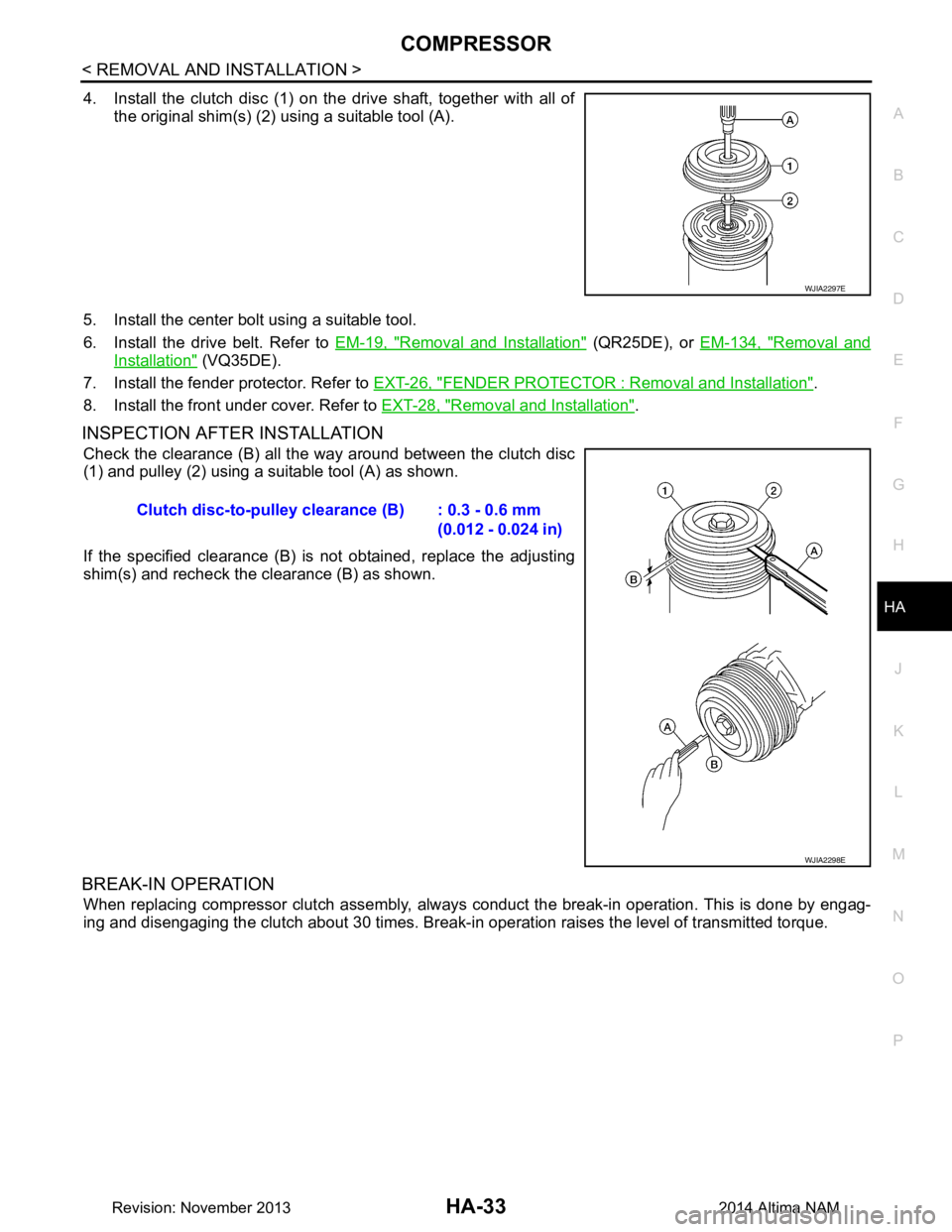
4. Install the clutch disc (1) on the drive shaft, together with all of the original shim(s) (2) using a suitable tool (A).
5. Install the center bolt using a suitable tool.
6. Install the drive belt. Refer to EM-19, "Removal and Installation"
(QR25DE), or EM-134, "Removal and
Installation" (VQ35DE).
7. Install the fender protector. Refer to EXT-26, "FENDER PROTECTOR : Removal and Installation"
.
8. Install the front under cover. Refer to EXT-28, "Removal and Installation"
.
INSPECTION AFTER INSTALLATION
Check the clearance (B) all the way around between the clutch disc
(1) and pulley (2) using a suitable tool (A) as shown.
If the specified clearance (B) is not obtained, replace the adjusting
shim(s) and recheck the clearance (B) as shown.
BREAK-IN OPERATION
When replacing compressor clutch assembly, always conduct the break-in operation. This is done by engag-
ing and disengaging the clutch about 30 times. Break-in operation raises the level of transmitted torque.
WJIA2297E
Clutch disc-to-pulley clearance (B) : 0.3 - 0.6 mm
(0.012 - 0.024 in)
WJIA2298E
Revision: November 20132014 Altima NAM
Page 2651 of 4801

HAC-2
Diagnosis Procedure ..............................................55
U1010 CONTROL UNIT (CAN) .........................56
Description ........................................................... ...56
DTC Logic ...............................................................56
Diagnosis Procedure ..............................................56
B2578, B2579 IN-VEHICLE SENSOR ...............57
DTC Logic ............................................................ ...57
Diagnosis Procedure ..............................................57
Component Inspection ............................................58
B257B, B257C AMBIENT SENSOR .................60
DTC Logic ............................................................ ...60
Diagnosis Procedure ..............................................60
Component Inspection ............................................61
B2581, B2582 INTAKE SENSOR ......................63
DTC Logic ............................................................ ...63
Diagnosis Procedure ..............................................63
Component Inspection ............................................64
B2630, B2631 SUNLOAD SENSOR .................66
DTC Logic ............................................................ ...66
Diagnosis Procedure ..............................................66
Component Inspection ............................................67
B2632, B2633 AIR MIX DOOR MOTOR
(DRIVER SIDE) ............................................... ...
69
DTC Logic ............................................................ ...69
Diagnosis Procedure ..............................................69
B2634, B2635 AIR MIX DOOR MOTOR (PAS-
SENGER SIDE) ............................................... ...
71
DTC Logic ............................................................ ...71
Diagnosis Procedure ..............................................71
B2636, B2637, B2638, B2639, B2654, B2655
MODE DOOR MOTOR ................................... ...
73
DTC Logic ............................................................ ...73
Diagnosis Procedure ..............................................73
B263D, B263E, B263F INTAKE DOOR MO-
TOR ................................................................. ...
75
DTC Logic ............................................................ ...75
Diagnosis Procedure ..............................................75
B27B0 A/C AUTO AMP. ....................................77
DTC Logic ............................................................ ...77
Diagnosis Procedure ..............................................77
POWER SUPPLY AND GROUND CIRCUIT .....78
A/C AUTO AMP. .................................................... ...78
A/C AUTO AMP. : Diagnosis Procedure ................78
AIR MIX DOOR MOTOR (DRIVER SIDE) .............. ...78
AIR MIX DOOR MOTOR (DRIVER SIDE) : Diag-
nosis Procedure ................................................... ...
78
AIR MIX DOOR MOTOR (PASSENGER SIDE) ..... ...79
AIR MIX DOOR MOTOR (PASSENGER SIDE) :
Diagnosis Procedure ............................................ ...
79
MODE DOOR MOTOR ........................................... ...80
MODE DOOR MOTOR : Diagnosis Procedure .......80
INTAKE DOOR MOTOR ........................................ ...81
INTAKE DOOR MOTOR : Diagnosis Procedure ....81
A/C SWITCH ASSEMBLY .........................................82
A/C SWITCH ASSEMBLY : Component Function
Check ................................................................... ...
82
A/C SWITCH ASSEMBLY : Diagnosis Procedure ...83
BLOWER MOTOR .......................................... ...84
Diagnosis Procedure ............................................ ...84
Component Inspection (Blower Motor) ...................85
Component Inspection (Front Blower Motor Re-
lay) ....................................................................... ...
85
MAGNET CLUTCH ............................................87
Component Function Check ................................ ...87
Diagnosis Procedure ...............................................87
A/C SWITCH ASSEMBLY SIGNAL CIRCUIT ...88
Diagnosis Procedure ...............................................88
DOOR MOTOR ..................................................89
Diagnosis Procedure ............................................ ...89
DOOR MOTOR COMMUNICATION CIRCUIT ...91
Diagnosis Procedure ............................................ ...91
ECV (ELECTRICAL CONTROL VALVE) ..........92
Diagnosis Procedure ............................................ ...92
Component Inspection ............................................93
SYMPTOM DIAGNOSIS ............................94
HEATER AND AIR CONDITIONING SYSTEM
CONTROL SYMPTOMS ................................. ...
94
Diagnosis Chart By Symptom .............................. ...94
INSUFFICIENT COOLING .................................96
Description ........................................................... ...96
Diagnosis Procedure ...............................................96
INSUFFICIENT HEATING .................................98
Description ........................................................... ...98
Diagnosis Procedure ...............................................98
COMPRESSOR DOES NOT OPERATE ...........99
Description ........................................................... ...99
Diagnosis Procedure ...............................................99
REMOVAL AND INSTALLATION .............101
A/C SWITCH ASSEMBLY .............................. ..101
Removal and Installation .......................................101
A/C AUTO AMP. ............................................. ..102
Exploded View ..................................................... .102
Removal and Installation .......................................102
Revision: November 20132014 Altima NAMRevision: November 20132014 Altima NAM
Page 2652 of 4801

HAC-3
C
D E
F
G H
J
K L
M A
B
HAC
N
O P
AMBIENT SENSOR ....................................... ..103
Removal and Installation .......................................103
IN-VEHICLE SENSOR ................................... ..104
Removal and Installation .......................................104
SUNLOAD SENSOR ...................................... ..105
Removal and Installation .......................................105
INTAKE SENSOR .......................................... ..106
Removal and Installation .......................................106
REFRIGERANT PRESSURE SENSOR ......... ..107
Removal and Installation .......................................107
DOOR MOTOR ............................................... ..108
Exploded View .................................................... ..108
INTAKE DOOR MOTOR ........................................ ..109
INTAKE DOOR MOTOR : Removal and Installa-
tion ...................................................................... ..
109
MODE DOOR MOTOR .......................................... ..109
MODE DOOR MOTOR : Removal and Installation ..109
AIR MIX DOOR MOTOR ....................................... ..109
AIR MIX DOOR MOTOR : Removal and Installa-
tion - Air Mix Door Motor (RH) ............................. ..
109
AIR MIX DOOR MOTOR : Removal and Installa-
tion - Air Mix Door Motor (LH) ............................. ..
109
MANUAL AIR CONDITIONER
PRECAUTION ................ ............................
110
PRECAUTIONS .............................................. ..110
Precaution for Supplemental Restraint System
(SRS) "AIR BAG" and "SEAT BELT PRE-TEN-
SIONER" ............................................................. ..
110
Precaution for Work ..............................................110
Working with HFC-134a (R-134a) .........................110
Precaution for Service Equipment .........................111
PREPARATION .........................................113
PREPARATION .............................................. ..113
Special Service Tool ........................................... ..113
Commercial Service Tool ......................................113
SYSTEM DESCRIPTION ...........................114
COMPONENT PARTS ................................... ..114
Component Part Location ................................... ..114
Component Description .........................................115
SYSTEM ...........................................................117
System Diagram .................................................. ..117
System Description ...............................................117
Air Flow Control .....................................................118
Air Inlet Control .....................................................118
Air Outlet Control ...................................................118
Compressor Control ..............................................118
Door Control ..........................................................119
Temperature Control ........................................... ..121
OPERATION ...................................................122
Switch Name and Function ....................................122
DIAGNOSIS SYSTEM (BCM) .........................124
CONSULT Function (BCM - COMMON ITEM) ......124
CONSULT Function (BCM - AIR CONDITIONER) ..125
DIAGNOSIS SYSTEM (IPDM E/R) .................126
CONSULT Function (IPDM E/R) ...........................126
ECU DIAGNOSIS INFORMATION ............128
FRONT AIR CONTROL ..................................128
Reference Value .................................................. ..128
ECM, IPDM E/R, BCM .....................................129
List of ECU Reference ...........................................129
WIRING DIAGRAM ....................................130
AIR CONDITIONER CONTROL ......................130
Wiring Diagram .................................................... ..130
BASIC INSPECTION .................................139
DIAGNOSIS AND REPAIR WORKFLOW ......139
Work Flow ............................................................ ..139
OPERATION INSPECTION ............................140
Work Procedure .....................................................140
DTC/CIRCUIT DIAGNOSIS .......................142
MODE DOOR MOTOR ....................................142
Diagnosis Procedure ........................................... ..142
AIR MIX DOOR MOTOR .................................144
Diagnosis Procedure .............................................144
INTAKE DOOR MOTOR .................................146
Diagnosis Procedure .............................................146
BLOWER MOTOR ..........................................148
Diagnosis Procedure .............................................148
Component Inspection (Blower Motor) ..................149
Component Inspection (Front Blower Motor Re-
lay) ....................................................................... ..
149
MAGNET CLUTCH .........................................151
Component Function Check ..................................151
Diagnosis Procedure .............................................151
POWER SUPPLY AND GROUND CIRCUIT
FOR FRONT AIR CONTROL ..........................
152
Description ........................................................... ..152
Component Function Check ..................................152
Diagnosis Procedure .............................................152
SYMPTOM DIAGNOSIS ............................154
Revision: November 20132014 Altima NAMRevision: November 20132014 Altima NAM
Page 2676 of 4801
![NISSAN TEANA 2014 Service Manual
DIAGNOSIS SYSTEM (A/C AUTO AMP.)HAC-27
< SYSTEM DESCRIPTION > [AUTOMATIC AIR CONDITIONER]
C
D E
F
G H
J
K L
M A
B
HAC
N
O P
NOTE:
Perform the inspection of each output device after starting the en NISSAN TEANA 2014 Service Manual
DIAGNOSIS SYSTEM (A/C AUTO AMP.)HAC-27
< SYSTEM DESCRIPTION > [AUTOMATIC AIR CONDITIONER]
C
D E
F
G H
J
K L
M A
B
HAC
N
O P
NOTE:
Perform the inspection of each output device after starting the en](/manual-img/5/57390/w960_57390-2675.png)
DIAGNOSIS SYSTEM (A/C AUTO AMP.)HAC-27
< SYSTEM DESCRIPTION > [AUTOMATIC AIR CONDITIONER]
C
D E
F
G H
J
K L
M A
B
HAC
N
O P
NOTE:
Perform the inspection of each output device after starting the engine, because the A/C compressor has been operating.
CONFIGURATION
Configuration includes the following functions.
CAUTION:
Use ‘‘Manual Configuration’’ only when ‘‘TY PE ID’’ of A/C auto amp. cannot be read.
Blower motor duty ratio 30% 30% 60% HI HI 60% HI
A/C compressor (Mag-
net clutch) ON ON ON OFF OFF ON ON
ECV duty 100% 100% 50% 0% 0% 100% 100% Te s t i t e m
MODE 1 MODE 2 MODE 3 MODE 4 MODE 5 MODE 6 MODE 7
Function Description
Read/Write Configuration Before replacing ECU
Allows the reading of vehicle specification (Type ID) written in A/C
auto amp. to store the specification in CONSULT.
After replacing ECU Allows the writing of vehicle information (Type ID) stored in CON-
SULT into the A/C auto amp.
Manual Configuration Allows the writing of vehicle specification (Type ID) into the A/C
auto amp. by hand.
Revision: November 20132014 Altima NAMRevision: November 20132014 Altima NAM
Page 2697 of 4801
![NISSAN TEANA 2014 Service Manual
HAC-48
< BASIC INSPECTION >[AUTOMATIC AIR CONDITIONER]
OPERATION INSPECTION
OPERATION INSPECTION
Work ProcedureINFOID:0000000009463110
DESCRIPTION
The purpose of the operational check is to che
ck th NISSAN TEANA 2014 Service Manual
HAC-48
< BASIC INSPECTION >[AUTOMATIC AIR CONDITIONER]
OPERATION INSPECTION
OPERATION INSPECTION
Work ProcedureINFOID:0000000009463110
DESCRIPTION
The purpose of the operational check is to che
ck th](/manual-img/5/57390/w960_57390-2696.png)
HAC-48
< BASIC INSPECTION >[AUTOMATIC AIR CONDITIONER]
OPERATION INSPECTION
OPERATION INSPECTION
Work ProcedureINFOID:0000000009463110
DESCRIPTION
The purpose of the operational check is to che
ck that the individual system operates normally.
INSPECTION PROCEDURE
1.CHECK MEMORY FUNCTION
1. Start the engine.
2. Operate the temperature control switch (drive r side) and raise the temperature setting to 32°C (90 °F).
3. Press the OFF switch.
4. Turn the ignition switch OFF.
5. Turn the ignition switch ON.
6. Press the AUTO switch.
7. Check that the temperature setting, before turning the ignition switch OFF, is stored.
Is the inspection result normal?
YES >> GO TO 2.
NO >> Check power and ground circuits for A/C auto amp. Refer to HAC-78, "A/C AUTO AMP. : Diagno-
sis Procedure".
2.CHECK BLOWER MOTOR SPEED
1. Operate the fan control dial. Check that the fan speed changes.
2. Check the operation for all fan speeds.
Is the inspection result normal?
YES >> GO TO 3.
NO >> Check blower motor system. Refer to HAC-84, "Diagnosis Procedure"
.
3.CHECK DISCHARGE AIR (MODE SWITCH AND DEF SWITCH)
1. Press the MODE switch and the DEF switch.
2. Check that the air outlets change according to each i ndicated air outlet by placing a hand in front of the
outlets. Refer to HAC-13, "System Description"
.
NOTE:
Confirm that the A/C compressor clutch is engaged (sound or visual inspection) and intake door position is at
FRE ( ) when the D/F ( ) or DEF ( ) is selected.
Is the inspection result normal?
YES >> GO TO 4.
NO >> Check mode door system. Refer to HAC-80, "MODE DOOR MOTOR : Diagnosis Procedure"
.
4.CHECK INTAKE AIR
1. Press the REC ( ) switch. Indicator is turned ON.
2. Press the FRE ( ) switch. Indicator is turned ON.
3. Listen for the intake door position change. (Slight change of blower sound can be heard.)
NOTE:
Confirm that the A/C compressor clutch is engaged (sound or visual inspection) and the FRE ( ) switch is
pressed when the D/F ( ) or DEF ( ) is selected.
Is the inspection result normal?
YES >> GO TO 5.
NO >> Check intake door system. Refer to HAC-81, "INTAKE DOOR MOTOR : Diagnosis Procedure"
.
5.CHECK A/C SWITCH
1. Press the A/C switch.
2. The A/C switch indicator is turned ON.
Confirm that the A/C compressor clutch engages (sound or visual inspection).
Is the inspection result normal?
Conditions : Engine running at normal operating temperature
Revision: November 20132014 Altima NAMRevision: November 20132014 Altima NAM