2014 NISSAN TEANA ignition
[x] Cancel search: ignitionPage 3893 of 4801
SEC-68
< DTC/CIRCUIT DIAGNOSIS >
P1610 LOCK MODE
DTC/CIRCUIT DIAGNOSIS
P1610 LOCK MODE
DescriptionINFOID:0000000009461106
ECM forcibly switches to the mode that inhibits engine start, when engine start operation is performed 5 times
or more while communication between ECM and BCM is not normal.
DTC LogicINFOID:0000000009461107
DTC DETECTION LOGIC
NOTE:
• If DTC B1610 is displayed with DTC U1000, first perform the trouble diagnosis for DTC U1000. Refer to BCS-68, "DTC Logic"
.
• If DTC B1610 is displayed with DTC U1010, first perform the trouble diagnosis for DTC U1010. Refer to BCS-69, "DTC Logic"
.
DTC CONFIRMATION PROCEDURE
1.PERFORM DTC CONFIRMATION PROCEDURE
1. Turn ignition switch ON.
2. Check DTC in “Self-Diagnostic Result” mode of “ENGINE” using CONSULT.
Is DTC detected?
YES >> Go to SEC-68, "Diagnosis Procedure".
NO >> Inspection End.
Diagnosis ProcedureINFOID:0000000009461108
1.CHECK ENGINE START FUNCTION
1. Check that there are no DTC’s except for DTC P1610 detected. If detected, erase the DTC after fixing.
2. Turn ignition switch OFF.
3. Contact the registered Intelligent Key backside to push-button ignition switch and wait 5 seconds.
4. Turn ignition switch ON.
5. Turn ignition switch OFF and wait 5 seconds.
6. Repeat steps 3 and 5 twice (a total of 3 times).
7. Check that engine can start.
>> Inspection End.
DTC No. Trouble diagnosis name DTC detecting condition Possible causeP1610 LOCK MODE When ECM detects a communication malfunction between
ECM and BCM 5 times or more. —
Revision: November 20132014 Altima NAMRevision: November 20132014 Altima NAM
Page 3894 of 4801
P1611 ID DISCORD, IMMU-ECMSEC-69
< DTC/CIRCUIT DIAGNOSIS >
C
D E
F
G H
I
J
L
M A
B
SEC
N
O P
P1611 ID DISCORD, IMMU-ECM
DTC LogicINFOID:0000000009461109
DTC DETECTION LOGIC
DTC CONFIRMATION PROCEDURE
1.PERFORM DTC CONFIRMATION PROCEDURE
1. Turn ignition switch ON.
2. Check DTC in “Self-Diagnostic Result ” mode of “ENGINE” using CONSULT.
Is DTC detected?
YES >> Go to SEC-69, "Diagnosis Procedure".
NO >> Inspection End.
Diagnosis ProcedureINFOID:0000000009461110
1.PERFORM INITIALIZATION
Perform initialization of BCM and reregistrati on of all Intelligent Keys using CONSULT.
Can the system be initialized and can the engine be started with reregistered Intelligent Key?
YES >> Inspection End.
NO >> GO TO 2.
2.CHECK SELF DIAGNOSTIC RESULT
1. Select “Self Diagnostic Result” mode of “ENGINE” using CONSULT.
2. Erase DTC.
3. Perform DTC CONFIRMATION PROCEDURE for DTC P1611. Refer to SEC-69, "DTC Logic"
.
Is DTC detected?
YES >> GO TO 3.
NO >> Inspection End.
3.REPLACE BCM
1. Replace BCM. Refer to BCS-80, "Removal and Installation"
.
2. Perform initialization of BCM and registration of all Intelligent Keys using CONSULT.
Can the system be initialized and can the engine be started with registered Intelligent Key?
YES >> Inspection End.
NO >> GO TO 4.
4.REPLACE ECM
1. Replace ECM. Refer to EC-540, "Removal and Installation"
(with QR25DE) or EC-997, "Removal and
Installation" (with VQ35DE).
2. Perform “ADDITIONAL SERVICE WHEN REPLACING ECM”. Refer to EC-174, "Work Procedure"
(with
QR25DE) or EC-679, "Work Procedure"
(with VQ35DE).
>> Inspection End.
DTC No. Trouble diagnosis name DTC detecting condition Possible cause
P1611 ID DISCORD, IMMU-ECM The ID verification results between BCM
and ECM are NG. • Harness or connectors
(The CAN communication line is open
or shorted.)
•BCM
•ECM
Revision: November 20132014 Altima NAMRevision: November 20132014 Altima NAM
Page 3895 of 4801
SEC-70
< DTC/CIRCUIT DIAGNOSIS >
P1612 CHAIN OF ECM-IMMU
P1612 CHAIN OF ECM-IMMU
DTC LogicINFOID:0000000009461111
DTC DETECTION LOGIC
NOTE:
• If DTC P1612 is displayed with DTC U1000, first perform the trouble diagnosis for DTC U1000. Refer to
BCS-68, "DTC Logic"
.
• If DTC P1612 is displayed with DTC U1010, first perform the trouble diagnosis for DTC U1010. Refer to BCS-69, "DTC Logic"
.
DTC CONFIRMATION PROCEDURE
1.PERFORM DTC CONFIRMATION PROCEDURE
1. Turn ignition switch ON.
2. Check DTC in “Self-Diagnostic Result” mode of “BCM” using CONSULT.
Is DTC detected?
YES >> Go to SEC-70, "Diagnosis Procedure".
NO >> Inspection End.
Diagnosis ProcedureINFOID:0000000009461112
NOTE:
• If DTC P1612 is displayed with DTC U1000, first perform the trouble diagnosis for DTC U1000. Refer to BCS-68, "DTC Logic"
.
• If DTC P1612 is displayed with DTC U1010, first perform the trouble diagnosis for DTC U1010. Refer to
BCS-69, "DTC Logic"
.
1.CHECK BCM POWER SUPPLY AND GROUND CIRCUIT.
Check BCM power supply and ground circuit. Refer to BCS-74, "Diagnosis Procedure"
.
Is the inspection result normal?
YES >> GO TO 2.
NO >> Repair or replace the harness.
2.CHECK ECM POWER SUPPLY AND GROUND CIRCUIT.
Check ECM power supply and ground circuit. Refer to EC-203, "Diagnosis Procedure"
.
Is the inspection result normal?
YES >> GO TO 3.
NO >> Repair or replace the harness.
3.PERFORM DTC CONFIRMATION PROCEDURE.
Perform the DTC confirmation procedure. Refer to SEC-70, "DTC Logic"
.
Does the DTC return?
YES >> Replace BCM. Refer to BCS-80, "Removal and Installation".
NO >> Inspection End.
DTC No. Trouble diagnosis name DTC detecting condition Possible cause
P1612 CHAIN OF BCM-ECM Inactive communication between BCM
and ECM • Harness or connectors
(The CAN communication line is open or
shorted.)
•ECM
•BCM
Revision: November 20132014 Altima NAMRevision: November 20132014 Altima NAM
Page 3896 of 4801
P1614 CHAIN OF IMMU-KEYSEC-71
< DTC/CIRCUIT DIAGNOSIS >
C
D E
F
G H
I
J
L
M A
B
SEC
N
O P
P1614 CHAIN OF IMMU-KEY
DTC LogicINFOID:0000000009461113
DTC DETECTION LOGIC
DTC CONFIRMATION PROCEDURE
1.PERFORM DTC CONFIRMATION PROCEDURE 1
1. Contact Intelligent Key back side to push-button ignition switch.
2. Check DTC in “Self-Diagnostic Result ” mode of “ENGINE” using CONSULT.
Is DTC detected?
YES >> GO TO SEC-71, "Diagnosis Procedure".
NO >> GO TO 2.
2.PERFORM DTC CONFIRMATION PROCEDURE 2
1. Press the push-button ignition switch.
2. Check DTC in “Self-Diagnostic Result ” mode of “ENGINE” using CONSULT.
Is DTC detected?
YES >> GO TO SEC-71, "Diagnosis Procedure".
NO >> Inspection End.
Diagnosis ProcedureINFOID:0000000009461114
Regarding Wiring Diagram information, refer to SEC-40, "Wiring Diagram".
1.CONNECTOR INSPECTION
1. Disconnect BCM and NATS antenna amp.
2. Check connectors and terminals for deformation, disconnection, looseness or damage.
Is the inspection result normal?
YES >> GO TO 2.
NO >> Repair or replace as necessary.
2.CHECK NATS ANTENNA AMP. CIRCUIT
1. Disconnect BCM connector and NATS antenna amp. connector.
2. Check continuity between BCM harness c onnector and NATS antenna amp. harness connector.
3. Check continuity between BCM harness connector and ground.
DTC No. Trouble diagnosis name DTC detecting condition Possible cause P1614 CHAIN OF IMMU-KEY Inactive communication between NATS
antenna amp. and BCM • Harness or connectors
(NATS antenna amp. circuit is open or
shorted.)
• NATS antenna amp.
•BCM
• Intelligent Key fob
BCM NATS antenna amp. Continuity
Connector Terminal Connector Terminal
M20 126
M40 3
Ye s
127 1
Revision: November 20132014 Altima NAMRevision: November 20132014 Altima NAM
Page 3897 of 4801
SEC-72
< DTC/CIRCUIT DIAGNOSIS >
P1614 CHAIN OF IMMU-KEY
Is the inspection result normal?
YES >> GO TO 3.
NO >> Repair or replace harness.
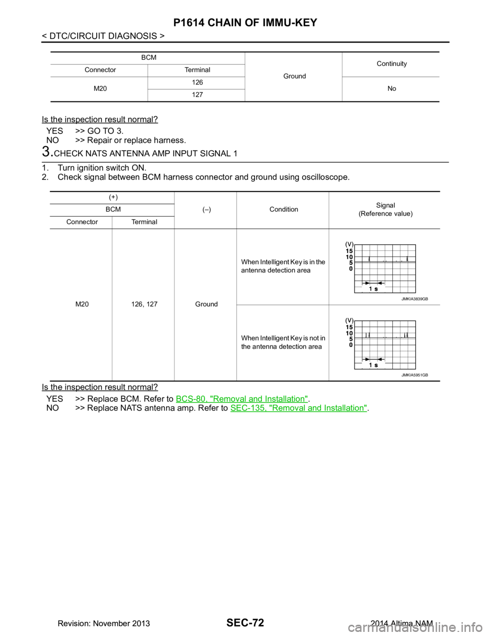
3.CHECK NATS ANTENNA AMP INPUT SIGNAL 1
1. Turn ignition switch ON.
2. Check signal between BCM harness connector and ground using oscilloscope.
Is the inspection result normal?
YES >> Replace BCM. Refer to BCS-80, "Removal and Installation".
NO >> Replace NATS antenna amp. Refer to SEC-135, "Removal and Installation"
.
BCM
GroundContinuity
Connector Terminal
M20 126
No
127
(+)
(–) Condition Signal
(Reference value)
BCM
Connector Terminal
M20 126, 127 Ground When Intelligent Key is in the
antenna detection area
When Intelligent Key is not in
the antenna detection area
JMKIA3839GB
JMKIA5951GB
Revision: November 20132014 Altima NAMRevision: November 20132014 Altima NAM
Page 3901 of 4801
SEC-76
< DTC/CIRCUIT DIAGNOSIS >
B210D STARTER RELAY
B210D STARTER RELAY
DTC LogicINFOID:0000000009461122
DTC DETECTION LOGIC
NOTE:
• If DTC B210D is displayed with DTC U1000, first perform the trouble diagnosis for DTC U1000. Refer to
BCS-68, "DTC Logic"
.
• If DTC B210D is displayed with DTC U1010, first perform the trouble diagnosis for DTC U1010. Refer to BCS-69, "DTC Logic"
.
• If DTC B210D is displayed with DTC B2617, first perform the trouble diagnosis for DTC B2617. Refer to
SEC-118, "DTC Logic"
.
DTC CONFIRMATION PROCEDURE
1.PERFORM DTC CONFIRMATION PROCEDURE
1. Ignition switch ON under the following conditions and wait for at least 1 second.
- CVT selector lever is in the P (Park) or N (Neutral) position
- Do not depress the brake pedal
2. Check “Self-diagnostic result” with CONSULT.
Is DTC detected?
YES >> Refer to SEC-76, "Diagnosis Procedure".
NO >> Inspection End.
Diagnosis ProcedureINFOID:0000000009461123
Regarding Wiring Diagram information, refer to SEC-29, "Wiring Diagram".
1. PERFORM SELF DIAGNOSTIC RESULT
Perform Self Diagnostic Result of IPDM E/R using CONSULT.
Is display history of DTC B210D CRNT?
YES >> GO TO 2.
NO >> Refer to GI-43, "Intermittent Incident"
.
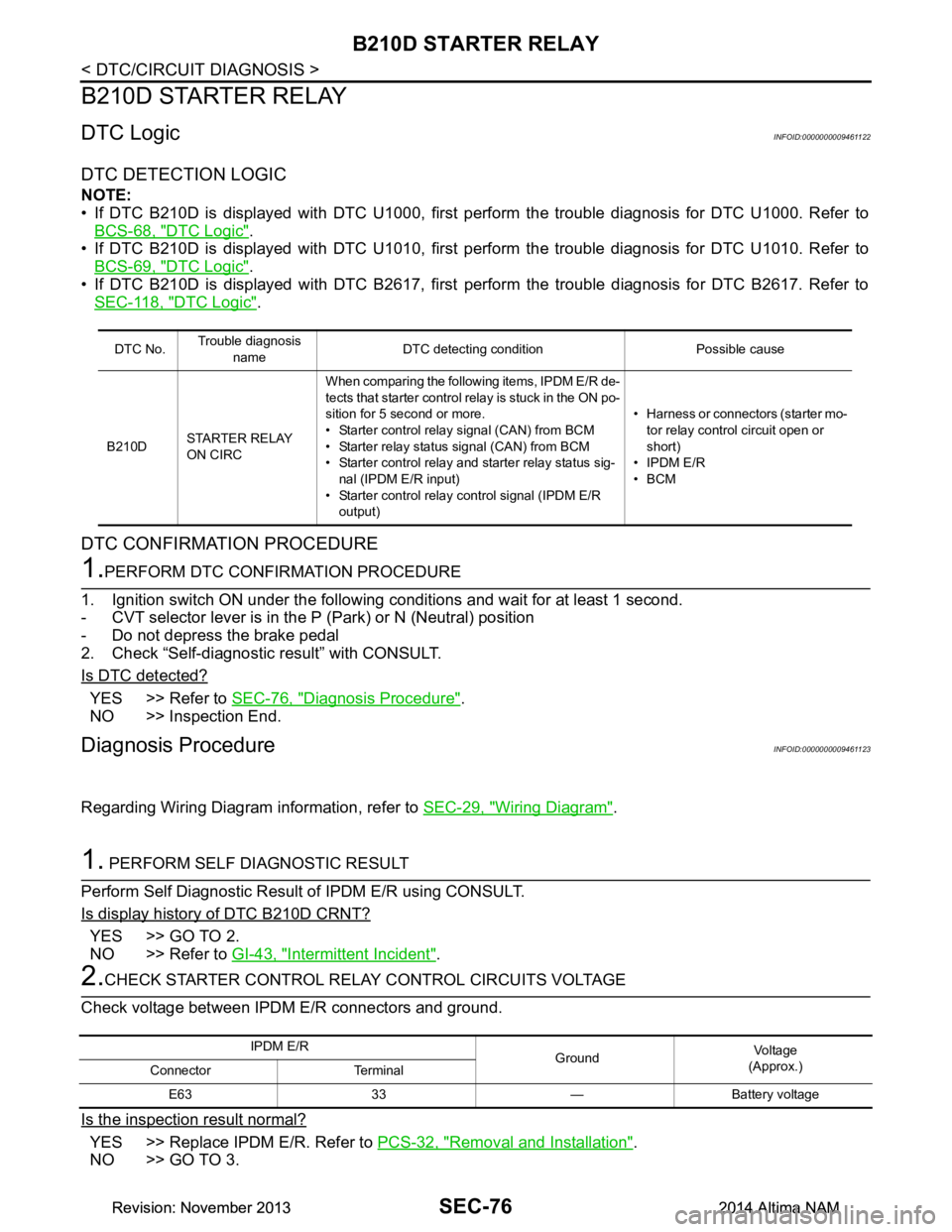
2.CHECK STARTER CONTROL RELA Y CONTROL CIRCUITS VOLTAGE
Check voltage between IPDM E/R connectors and ground.
Is the inspection result normal?
YES >> Replace IPDM E/R. Refer to PCS-32, "Removal and Installation".
NO >> GO TO 3.
DTC No. Trouble diagnosis
name DTC detecting condition Possible cause
B210D STARTER RELAY
ON CIRC When comparing the following items, IPDM E/R de-
tects that starter control relay is stuck in the ON po-
sition for 5 second or more.
• Starter contro l relay signal (CAN) from BCM
• Starter relay status signal (CAN) from BCM
• Starter control relay and starter relay status sig-
nal (IPDM E/R input)
• Starter control relay control signal (IPDM E/R
output) • Harness or connectors (starter mo-
tor relay control circuit open or
short)
• IPDM E/R
•BCM
IPDM E/R GroundVo l ta g e
(Approx.)
Connector Terminal
E63 33 — Battery voltage
Revision: November 20132014 Altima NAMRevision: November 20132014 Altima NAM
Page 3903 of 4801

SEC-78
< DTC/CIRCUIT DIAGNOSIS >
B210E STARTER RELAY
B210E STARTER RELAY
DTC LogicINFOID:0000000009461125
DTC DETECTION LOGIC
NOTE:
• If DTC B210E is displayed with DTC U1000, first perform the trouble diagnosis for DTC U1000. Refer to
BCS-68, "DTC Logic"
.
• If DTC B210E is displayed with DTC U1010, first perform the trouble diagnosis for DTC U1010. Refer to
BCS-69, "DTC Logic"
.
• When IPDM E/R power supply voltage is low (Approx. 7 - 8 V for about 1 second), the DTC B210F may be
detected.
DTC CONFIRMATION PROCEDURE
1.PERFORM DTC CONFIRMATION PROCEDURE
1. Turn ignition switch ON under the following conditions and wait for at least 1 second.
- CVT selector lever is in the P (Park) or N (Neutral) position
- Do not depress the brake pedal
2. Check Self-diagnostic result with CONSULT.
Is DTC detected?
YES >> Refer to SEC-78, "Diagnosis Procedure".
NO >> Inspection End.
Diagnosis ProcedureINFOID:0000000009461126
Regarding Wiring Diagram information, refer to SEC-29, "Wiring Diagram".
1. PERFORM SELF DIAGNOSTIC RESULT
Perform Self Diagnostic Result of IPDM E/R using CONSULT.
Is display history of DTC B210E CRNT?
YES >> GO TO 2.
NO >> Refer to GI-43, "Intermittent Incident"
.
2.CHECK STARTER CONTROL RELA Y CONTROL CIRCUITS VOLTAGE
Check voltage between IPDM E/R connectors and ground.
Is the inspection result normal?
YES >> Replace IPDM E/R. Refer to PCS-32, "Removal and Installation".
NO >> GO TO 3.
DTC No. Trouble diagnosis
name DTC detecting condition Possible cause
B210E STARTER RELAY
OFF When comparing the following items, IPDM E/R de-
tects that starter control relay is stuck in the OFF po-
sition for 5 second or more.
• Starter control relay signal (CAN) from BCM
• Starter relay status signal (CAN) from BCM
• Starter control relay and st arter relay status signal
(IPDM E/R input)
• Starter control relay cont rol signal (IPDM E/R out-
put) • IPDM E/R
•BCM
•Battery
IPDM E/R GroundVo l ta g e
(Approx.)
Connector Terminal
E63 33 — Battery voltage
Revision: November 20132014 Altima NAMRevision: November 20132014 Altima NAM
Page 3905 of 4801

SEC-80
< DTC/CIRCUIT DIAGNOSIS >
B210F TRANSMISSION RANGE SWITCH
B210F TRANSMISSION RANGE SWITCH
DescriptionINFOID:0000000009461127
IPDM E/R confirms the shift position with the following signals.
• Transmission range switch
• Shift position signal from BCM (CAN)
DTC LogicINFOID:0000000009461128
DTC DETECTION LOGIC
NOTE:
• If DTC B210F is displayed with DTC U1000, first perform the trouble diagnosis for DTC U1000. Refer to BCS-68, "DTC Logic"
.
• If DTC B210F is displayed with DTC U1010, first perform the trouble diagnosis for DTC U1010. Refer to
BCS-69, "DTC Logic"
.
DTC CONFIRMATION PROCEDURE
1.PERFORM DTC CONFIRMATION PROCEDURE
1. Turn ignition switch ON under the following conditions and wait for at least 1 second.
- CVT selector lever is in the P (Park) or N (Neutral) position
- Do not depress the brake pedal
2. Check Self-diagnostic result with CONSULT.
Is DTC detected?
YES >> Refer to SEC-80, "Diagnosis Procedure".
NO >> Inspection End.
Diagnosis ProcedureINFOID:0000000009461129
Regarding Wiring Diagram information, refer to SEC-29, "Wiring Diagram" or SEC-40, "Wiring Diagram".
1.CHECK DTC WITH BCM
Refer to BCS-52, "DTC Index"
.
Is the inspection result normal?
YES >> GO TO 2.
NO >> Repair or replace malfunctioning parts.
2.CHECK TRANSMISSION RANGE SWITCH INPUT SIGNAL
1. Turn ignition switch OFF.
2. Disconnect IPDM E/R harness connector.
3. Turn ignition switch ON.
4. Check voltage between IPDM E/R harness connector E63 terminal 37 and ground under following condi-
tion.
DTC No. Trouble diagnosis name DTC detecting condition Possible cause
B210F TRANSMISSION
RANGE SWITCH IPDM E/R detects a mismatch between the signals
below for 1 second or more.
• Transmission range switch input signal
• Shift position signal from BCM (CAN) • Harness or connectors
Transmission range switch circuit is
open or shorted
• Transmission range switch
Revision: November 20132014 Altima NAMRevision: November 20132014 Altima NAM